
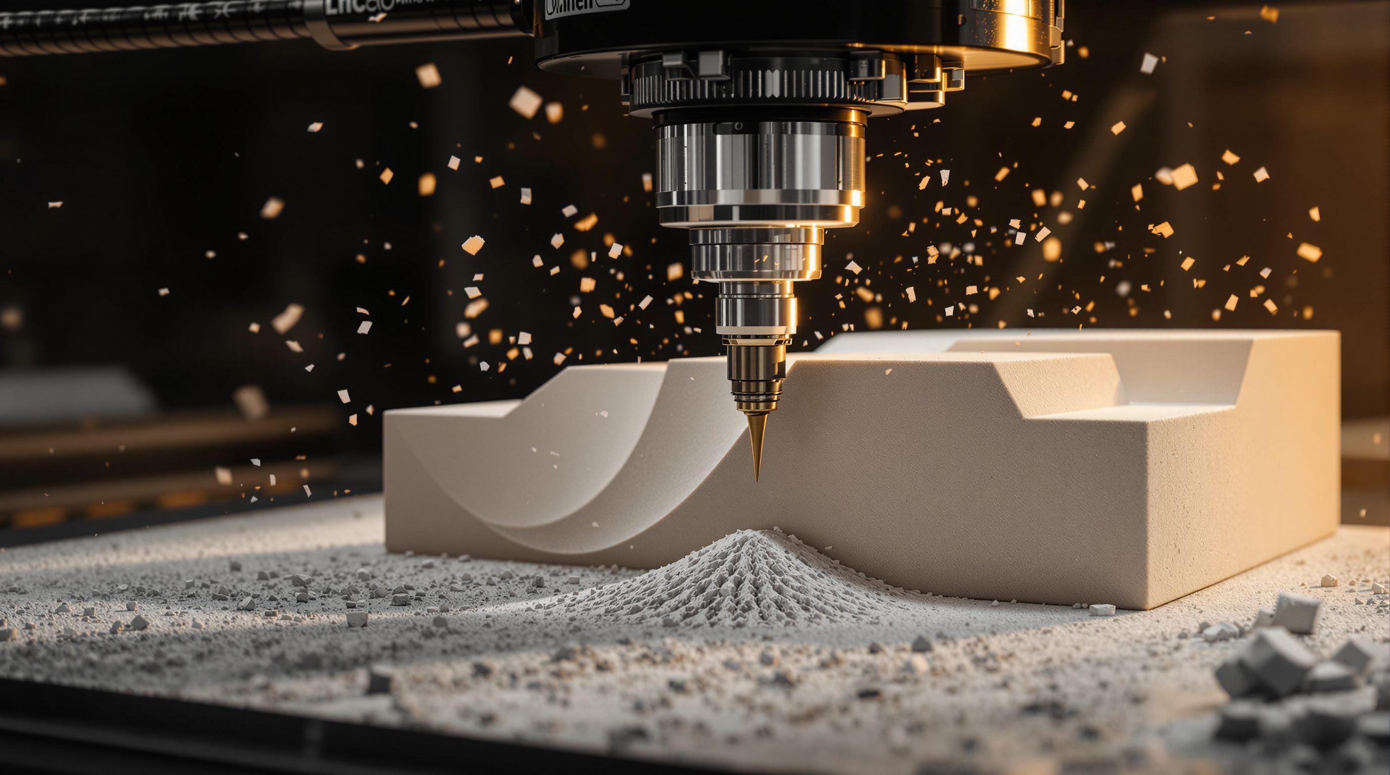
 Lesson 0.2
Lesson 0.2 · Foundations of Digital Fabrication
The File-to-Factory Paradigm
The pipeline in depth - CAD model to CAM to post-processor to G-code to controller to made part
There is not one hand-off between your model and the machine - there are five, and each one can quietly drop something you cared about.
The phrase file to factory sounds like a single leap: model on the left, finished part on the right. Open the box and you find a relay race - a chain of programs and files, each handing geometry to the next in a slightly poorer language than the one before.
Understanding that relay is the difference between a maker who trusts the machine blindly and one who knows exactly where a curve became a set of flat facets, where millimetres became inches, and where the last drop of design intent turned into pure motion. This lesson walks the whole chain, names every format, and shows what survives each translation.
Information only leaves as you go down the pipeline. Export dumb formats last.
The pipeline, stage by stage
In the last lesson we drew the file-to-factory chain as five links. Now we open each one. It begins in CAD, where you build the geometry - a solid, a surface, or a 2D profile - carrying design intent: dimensions, relationships, sometimes a full edit history. That model is handed to CAM (computer-aided manufacturing), which is where making decisions enter: you choose a tool, a strategy (pocket, contour, drill), a feed rate and a spindle speed, and CAM computes the toolpath - the exact route the cutting tip or nozzle will travel.
CAM does not yet speak the machine's dialect. A post-processor translates the generic toolpath into the specific flavour of G-code your controller understands - a Haas mill, a GRBL laser and a Prusa printer all read subtly different G-code. That text file of moves goes to the machine controller, the small computer that turns lines like G1 X40 Y20 F800 into coordinated motor pulses. The motors drive the axes, the tool meets the material, and out comes the physical part. Five stages, five programs or files, each a genuine translation. Read any fabrication job as this pipeline and you always know which stage to interrogate when something goes wrong - a bad surface is usually CAM, a machine that refuses the file is usually the post-processor, and a part that is the wrong size is almost always units or origin.
CAD -> CAM -> post -> G-code -> controller -> part. Five translations, not one leap.
The hand-offs are file formats
Between the stages sit files, and the format of each file decides what can pass through. The richest are native and neutral solid formats. A native file (.3dm for Rhino, .skp for SketchUp, a parametric part file) keeps everything - solids, surfaces, units, often the construction history. STEP (.step, .stp) is the neutral exchange standard for solids: it hands a watertight solid model between programs without the edit history but with true faces, edges and units intact. This is what you send when the geometry must stay exact and editable downstream.
Below that live the dumb-geometry formats. STL describes a 3D shape as nothing but a mesh of triangles - no curves, no faces, no units guaranteed - which is why it is the workhorse of 3D printing but useless if you later need to edit the design. DXF carries 2D curves and lines, the standard input for laser cutters and 2D CNC, but it is only outlines - it knows nothing of thickness or material. At the very bottom is G-code itself: no geometry remains at all, only a list of coordinated moves for one particular machine. The rule to internalise: information only ever leaves as you move down the pipeline. Choose the highest-fidelity format each stage can accept, and export to the dumb formats as late as possible.
What each translation keeps and drops
Every hand-off is lossy in a predictable way, and knowing the failure modes lets you catch them before they cost material. The most famous loss happens at STL export: a smooth curve has no triangles, so the exporter approximates it with flat facets. The chord tolerance (sometimes called deviation) sets how far a facet may stray from the true surface - set it too coarse and a printed cylinder comes out visibly faceted; set it too fine and the file balloons to hundreds of megabytes. A typical setting is a deviation of around 0.01-0.05 mm for detailed prints, but the point is that resolution becomes a choice you make, not a property of the geometry.
Other losses are quieter. Exporting to DXF can drop layer names, arc definitions (splitting a smooth arc into many short segments), or the sense of which loops are holes. Moving between programs can silently change units - a model built in millimetres reopened as inches is now 25.4 times too big. Native construction history - the parametric relationships that let you change a dimension and have everything update - is gone the moment you export to any exchange format. None of this is a flaw to be angry about; it is the physics of translation. The maker's job is to know which stage owns which risk and to verify at each boundary rather than trust blindly all the way to a ruined workpiece.
STL turns a curve into flat facets. Chord tolerance is YOUR call, not the geometry's.
The post-processor and controller - the last mile
The two least-understood stages are the post-processor and the controller, and both live very close to the metal. A post-processor is a small program, specific to your machine, that converts CAM's neutral toolpath into the exact G-code dialect the controller expects. Dialects really do differ: the code to turn a spindle on, to select a tool, to set an offset, or to dwell varies between a Fanuc controller, a Haas, a GRBL board and a Marlin 3D-printer firmware. Use the wrong post and the machine may ignore a command, crash into a clamp, or simply refuse to run. This is why fablabs are strict about which post you use for which machine - it is not bureaucracy, it is collision avoidance.
The controller is the real-time brain. It reads G-code line by line, plans acceleration so the axes do not lurch, and issues step pulses to the motors, all while watching limit switches and, on a printer, temperatures. G-code is deliberately simple: G0 is a rapid non-cutting move, G1 is a controlled feed move, M3 starts the spindle, M104 sets a hotend temperature. You almost never write it by hand, but reading a few lines demystifies the machine completely - you can see the origin it assumes, the units mode (G20 inch, G21 millimetre), and the feed rate it will hold. When a job behaves strangely, opening the G-code in a viewer is often faster than re-running CAM.
One subtlety worth naming: the controller also holds settings the file does not - the machine's calibration, its work-offset table, backlash compensation and maximum feeds. So the same G-code can behave differently on two machines of the same model if their offsets differ. This is why an experienced maker treats the post-processor and controller as a matched pair, tied to one physical machine, and re-verifies the origin on the bed before every run rather than assuming the last job left it correct.
Wrong post-processor = wrong dialect = a machine that ignores you or crashes.
Why file-driven making changed design
None of this pipeline detail is trivia - it is why digital fabrication changed how designers think. When the model directly drives the machine, the loop between drawing and holding the real thing shrinks from weeks to hours. You can print a joint, feel that it is too tight, edit one parameter, and re-cut before lunch. That tight feedback loop turns design into an experimental craft again, where you learn from material rather than only from screens.
It also relocates authority. In the old chain, a contractor or craftsperson interpreted your drawings and absorbed the ambiguity; in the file-to-factory chain, whatever is in the file is what gets made, exactly, including your mistakes. That is a gift and a discipline - the designer's control now reaches the finished surface, but so does the designer's responsibility for tolerances, units and clearances. Finally, because the pipeline is data end to end, it composes with computation: a parametric definition can generate a thousand unique files and feed them straight to the machine, which is the technical basis of mass customization. The lesson to carry forward is that the pipeline is the product. Master the hand-offs and you can make almost anything the machines allow; ignore them and the most beautiful model in the world dies quietly at an export dialog.
STEP (.step / .stp)
Neutral exchange format for solid models
Carries true solids, faces and units between programs without native edit history. Send this when geometry must stay exact and editable.
STL
Triangle-mesh format, the workhorse of 3D printing
Describes a shape as a mesh only - no curves, no units guaranteed. Great for printing, useless for later editing; watch the chord tolerance.
DXF
2D vector format for laser and 2D CNC
Outlines and curves only, no thickness or material. Can drop layers or split arcs into short segments if exported carelessly.
Post-processor
Translates CAM toolpaths into a machine's G-code dialect
Machine-specific. The wrong post produces the wrong dialect - a machine that ignores commands or crashes. Match it exactly to the controller.
G-code
The low-level move language a controller runs
G0 rapid, G1 feed, G20/G21 inch/mm, M3 spindle. You rarely write it, but reading a few lines reveals the origin and units the machine assumes.
Workshop — trace one part through the whole pipeline
You do not need a machine to learn the pipeline - you need one object and the discipline to follow it backwards through every hand-off. This builds the mental model that makes real jobs debuggable.
Pen and paper are enough. Optional and free: a slicer (Cura, PrusaSlicer) to see STL faceting, or any online G-code viewer to read the moves. A fablab makes it tangible but is not required for the concept.
Goal: map one part across all five stages and every format between them
Inputs: a simple object (a bracket, a coaster, a nameplate), pen and paper, optionally free CAD/CAM viewers
Time: ~30 minutes
- 1Pick a simple part and sketch it. Decide the process (laser, CNC or 3D print) and therefore which family it belongs to - that choice sets the whole pipeline.
- 2Write the five stages as a column: CAD -> CAM -> post-processor -> G-code -> controller -> part. Next to each arrow, name the file format that crosses it (for a laser: model -> DXF; for a print: model -> STL -> sliced G-code).
- 3For each hand-off, note what is preserved and what is dropped. Where does a curve become facets? Where could units change? Where is the design history lost for good?
- 4If you can, open a free viewer (a slicer for STL, an online G-code viewer) and export your part. Deliberately set a coarse chord tolerance, then a fine one, and compare the faceting and file size.
- 5Mark the single stage you think is most likely to ruin the part in practice, and write one sentence on how you would verify that boundary before pressing go.
You’ll walk away with
A one-page pipeline map for your chosen part: five stages, the format on each arrow, what each translation keeps and drops, and the one boundary you would check first. This is the debugging map you will reuse on every real job.
Three altitudes on the same idea
Read the band that fits you — or all three.
Specify at the right fidelity and the building actually gets built as drawn. When you hand a fabricator a STEP solid rather than a flattened DXF, panel geometry, units and edges survive the trip. Knowing the pipeline lets you write fabrication information that a shop can execute without re-modelling - and lets you interrogate a bad component at the correct stage.
This is why a bespoke piece comes back right - or wrong. A CNC-milled desk or laser-cut screen is only as good as the file you send. Export curves as true arcs, keep your units in millimetres, and set a sensible chord tolerance for any 3D-printed fitting, and the maker reproduces your intent exactly rather than a faceted approximation of it.
Learn to read the pipeline and no machine will intimidate you again. Every fablab job is CAD to CAM to post to G-code to controller to part. When your first laser cut comes out scaled wrong or your print is faceted, you will know precisely which hand-off to check. Being the person who can debug a file is a portfolio-grade skill in itself.
“Once my model looks right, exporting to STL or DXF and sending it to the machine is just a formality.”
Do it yourself
No machine needed - reason through the relay.
- 1Name the five stages of the file-to-factory pipeline in order.
- 2Which format would you send to keep a solid exact and editable - STEP or STL - and why?
- 3What exactly does STL drop when it exports a smooth curved surface?
- 4What does a post-processor do, and what goes wrong if it is the wrong one?
- 5Give one reason a part might come out 25.4 times too big.
The one line to carry out
Peer-reviewed journals & authoritative standards
- 01Computer-aided manufacturing (CAM) — Wikipedia, 2026.
- 02G-code — Wikipedia, 2026.
- 03Numerical control (CNC) — Wikipedia, 2026.
- 04Iwamoto, L. — Digital Fabrications: Architectural and Material Techniques — Princeton Architectural Press, 2009.
The pipeline treats every process the same, but the machines at the end are not the same. Next we sort them into the three great families - subtractive, additive and formative - and learn to pick the right one for a given material, scale and geometry.
The author
Amogh N P
Architect, interior designer, and creative polymath. Studio Matrx began in his notebooks — his vision of design made honest, useful, and open to everyone. Its Academy is written and taught in his memory, and free, forever.
More about Amogh →