
 Lesson 1.1
Lesson 1.1 · CAD/CAM & Toolpaths
From Model to Machine
How a CAD model becomes a machine-ready file - format, CAM, and where zero is
Your model is beautiful on screen and useless to a machine - until someone tells the machine where the material is and how to reach it.
A finished CAD model feels like the end of the work. To a machine it is barely the beginning. The model describes shape; a machine needs instructions - which tool, how fast, how deep, in what order, and above all, where the material actually sits on the bed.
This lesson is the handover: the sequence of decisions that turns geometry into a job a machine can run. Get the model, the export, the CAM setup and the work origin right and the part comes off the machine matching the screen. Get any one wrong and you cut air, crash a tool, or make a beautifully precise version of the wrong thing.
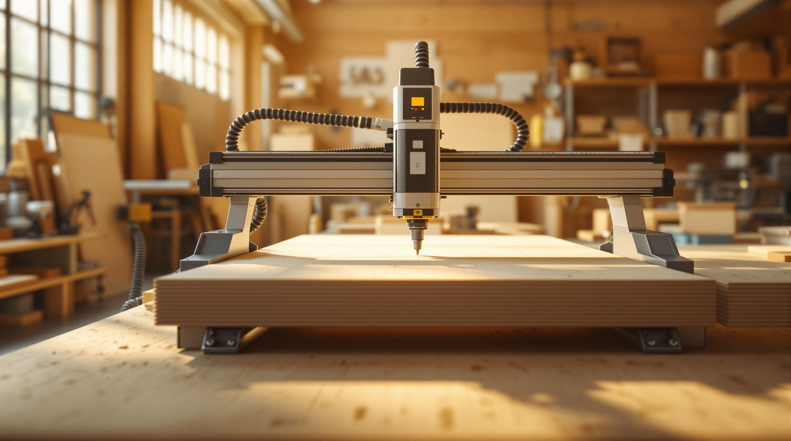
Model zero = work origin = the point on the real stock. Everything hangs off it.
Model with the machine already in mind
Fabrication starts long before CAM - it starts in how you model. A model built only to look right on screen often cannot be made; a model built to be fabricated carries the process in its geometry. Practically, that means clean, closed geometry (a 3D print needs a watertight mesh - no holes, no flipped normals, no self-intersections; a solid model needs real solids, not loose surfaces), and it means modelling to real material.
If you are cutting 18 mm plywood, every slot, tab and thickness in the model should reference that actual measured sheet - not a nominal 18 mm, because a sheet sold as 18 mm often measures 17.4. If you are milling, avoid geometry a tool physically cannot reach: sharp internal corners, deep narrow pockets, undercuts a straight tool cannot see. The habit to build now is to model as the machine will make it: right thickness, reachable features, and joints sized for the process. A model that ignores the machine just pushes every problem downstream to the point where material and time are already spent.
There is a second, quieter benefit to modelling this way: the model stays editable. Drive thickness, kerf and tab sizes from named parameters or dimensions rather than baking them into fixed geometry, and when the real sheet measures 17.4 instead of 18 you change one number and the whole part updates. A parametric or history-based model (in Fusion 360, SolidWorks, or a Grasshopper definition) is worth far more to a fabricator than a dead lump of surfaces, because fabrication is iterative - the first cut teaches you something, and you want to fold that lesson back into the file in seconds, not rebuild it. Modelling for the machine and modelling to stay editable are the same discipline seen from two sides.
Model the real sheet, not the nominal one. 18 mm ply is often 17.4.
Export the right format for the job
The file format is the passport between programs, and the wrong one loses information. The rough rule: meshes for additive, precise geometry for subtractive.
For 3D printing, you export a mesh - STL (triangles, the long-time default) or the newer 3MF (which also carries units, colour and materials). A mesh approximates curves with flat facets, so export at a fine enough resolution that the facets do not show, but not so fine the file becomes unwieldy. For laser and 2D routing you export vectors - DXF or SVG - clean, closed polylines at 1:1 scale, because the machine cuts exactly the lines you give it; stray double lines or open curves cause double-cuts or skipped paths. For CNC milling and anything needing true curves, export STEP (or IGES) - a precise boundary representation that keeps arcs as arcs, not as chords. Two things trip everyone: units (a model exported in inches and read as millimetres comes out 25.4 times too small - always confirm), and scale/origin (export at 1:1 with a sensible origin). Check the exported file in a viewer before you trust it; a two-second look catches most disasters.
The deeper distinction underneath the file extensions is mesh versus solid. A mesh (STL, OBJ, 3MF) is a skin of flat triangles - light, universal, but an approximation with no true curves and no editable history, so once it is a mesh it is hard to change. A solid or boundary-representation model (STEP, native CAD) carries exact geometry the CAM can offset and analyse precisely. As a rule, stay in precise solid or vector geometry as far down the pipeline as you can and convert to mesh only at the last moment, for the process that needs it - that keeps your options open and your dimensions honest. And whatever you export, name and version the file clearly; a workshop full of finalfinalv3.dxf files is a workshop about to cut the wrong one.
Mesh (STL/3MF) for printing. Vectors (DXF/SVG) for lasers. STEP for milling curves.
What CAM actually adds
CAM - computer-aided manufacturing - is where a shape becomes a plan. Programs like Fusion 360, RhinoCAM, VCarve or Mastercam take your exported geometry and let you answer the questions the model cannot: which tool (a 6 mm flat end mill, a 60-degree V-bit, a 0.4 mm print nozzle), how fast to feed and spin (feed rate and spindle speed), how the tool should travel (the toolpaths of the next lesson), and in what order. You define the stock - the block or sheet you are cutting from - so CAM knows what is solid and what is air, and you build or pick from a tool library so its calculations match the real cutter in the machine.
CAM then generates toolpaths and, crucially, simulates them - a coloured animation of the tool removing material - so you can catch a plunge into a clamp or a gouge before it happens in aluminium. Finally a post-processor translates the generic toolpath into the specific dialect of G-code your machine reads, because a Haas mill, a GRBL router and a Prusa printer all speak slightly different flavours. CAM is the difference between a shape and a runnable job.
CAM answers what the model cannot: which tool, how fast, what order.
Coordinate systems, work origin and setup
Here is the single idea that ties everything together: the machine and your model must agree on where zero is. A machine thinks in X, Y and Z - a right-handed coordinate system. It has its own fixed machine coordinates (often called G53), set by its home switches. But your part is not bolted to the machine home; it sits wherever you clamped it. So you define a work coordinate system - a work origin, commonly G54 - by touching the tool to a chosen point on the actual stock and telling the machine this point equals model zero.
Everything the toolpath does is measured from that origin. Set it on a corner of the sheet, a dowel-pin datum, or a machined feature - but choose something repeatable, so that if you flip the part or run a second sheet, the origin lands in the same place. Get the work origin wrong and the whole job shifts: the part is cut in the right shape but the wrong place, off the edge of the stock, or into a clamp.
Setting the origin has real technique behind it. In X and Y you touch off an edge, use an edge-finder or a probe, or register the stock against fixed dowels; in Z you decide whether zero sits on the top of the stock (common, so cut depths read as negative numbers into the material) or the bed (so a cut-through path is safe even if the stock is thinner than expected). On a mill you must also account for tool length offsets, because each tool in the changer is a different length - the machine measures or you set how far each sticks out, so a tool change does not plunge the new tool too deep. And this is why fixturing matters as much as the origin - the stock must not shift mid-cut, or the material drifts out from under a correct toolpath. Model zero, work origin, tool offsets and a solid fixture together make one promise: that the geometry lands on the real material exactly where you designed it.
Machine coords are fixed to the machine. Work coords (G54) are fixed to YOUR part.
The setup sheet: making it repeatable
The last artefact of the handover is the setup sheet - the one-page summary CAM produces (or you write) that lets someone, including future-you, run the job without guessing. It lists the stock size and material, where the work origin is, every tool in order with its number and the feeds and speeds, the total run time, and any notes (flip halfway, change to the V-bit at operation three, watch the clamp on the left).
A good setup sheet is what separates a one-off you got lucky with from a process you can repeat and hand to someone else. It is also your safety net: reading it aloud against the machine before you press start - right tool loaded, origin set, stock clamped, nobody in the path - catches the mistakes that turn expensive. Fabrication is a team relay, and the setup sheet is the baton.
CAM (Fusion 360, RhinoCAM, VCarve, Mastercam)
Software that turns geometry into a machine job
Sets stock, tools, feeds and toolpaths, simulates the cut, then posts G-code. The bridge between CAD and the machine.
STL / 3MF / STEP / DXF
Exchange formats between CAD and CAM
Meshes (STL, 3MF) for printing; precise geometry (STEP) for milling; vectors (DXF, SVG) for lasers. Wrong format loses information.
Work coordinate system (G54) / work origin
Where the machine and the model agree zero is
You set it on the real stock. Everything the toolpath does is measured from it; get it wrong and the whole job shifts.
Post-processor
Translator from generic toolpath to machine-specific G-code
A Haas mill, a GRBL router and a Prusa printer read slightly different dialects; the post matches the code to the machine.
Workshop - take one model all the way to a setup sheet
You can do this with free software and no machine. The goal is to feel the whole handover - model, export, CAM, origin, setup sheet - on one simple part, so that when you reach a real machine the sequence is already familiar.
A computer with free CAD/CAM (Fusion 360 personal use, FreeCAD, or Rhino with a CAM plug-in) and a notebook. Optional: a real laser or CNC at a fablab to actually run your setup sheet under supervision.
Goal: convert one CAD part into a machine-ready plan on paper
Inputs: a simple part (a slotted bracket or a coaster), free CAD/CAM (Fusion 360 personal, or Rhino + a CAM plug-in), a notebook
Time: ~45 minutes
- 1Model a simple part sized to a real material you could buy - say a 100 x 100 mm coaster from measured 5.8 mm ply, or a bracket from 3 mm acrylic. Note the ACTUAL thickness, not the nominal.
- 2Export it twice: once as a vector (DXF or SVG) as if for a laser, once as a mesh (STL) as if for a printer. Open each in a viewer and check units and scale - is it the size you intended, or 25.4x off?
- 3Load the geometry into CAM. Define the stock, pick a tool from the library, and set a feed rate and spindle speed (use the tool maker's suggested values). Generate one profile toolpath.
- 4Set a work origin explicitly - choose a corner or datum and note WHERE it is. Then run the CAM simulation and watch the tool remove material; look for any plunge into stock that should be air.
- 5Export the setup sheet (or write your own): stock, material, work origin, tool list with feeds and speeds, run time, and one safety note. This one page is the deliverable.
You’ll walk away with
One simple part carried from CAD to a written setup sheet, plus the two exports (vector and mesh) checked for units and scale. You have walked the entire model-to-machine handover without cutting anything.
Three altitudes on the same idea
Read the band that fits you — or all three.
Understanding the handover lets you specify fabrication credibly. You do not have to run the post-processor yourself, but knowing that a model must be watertight, exported in the right format, and referenced to a real work origin means you can hand a fabricator a file that works - and read their pushback intelligently when a detail cannot be made from the geometry you drew.
This is why the joinery you send sometimes comes back wrong. A screen or a reception desk cut from your file depends on the file being clean, at 1:1, in the right units, and dimensioned to the real sheet thickness. Model to the material you will actually buy, and the made piece matches your drawing instead of surprising you by a few millimetres.
Learn the model-to-machine chain once and every machine in the fablab makes sense. Watertight geometry, the right export, CAM setup, work origin, setup sheet - the same five ideas recur at the laser, the router and the printer. Master the handover and you become the person in the studio whose files just run.
“If the model looks right in CAD, it is ready to fabricate - just hit export and print or cut.”
Do it yourself
No machine needed - reason each one through.
- 1Why does a model that renders perfectly sometimes fail to fabricate?
- 2Which export format would you use for a laser cut, a 3D print, and a milled curved part - and why?
- 3In your own words, what is the difference between machine coordinates and a work origin?
- 4What four things does CAM add that a CAD model does not carry?
- 5Why should you dimension a plywood joint to the measured thickness rather than the nominal one?
The one line to carry out
Peer-reviewed journals & authoritative standards
- 01Computer-aided manufacturing (CAM) — Wikipedia, 2026.
- 02Numerical control (CNC) — Wikipedia, 2026.
- 03G-code — Wikipedia, 2026.
- 04The Fab Foundation - the global Fab Lab network — Fab Foundation, 2026.
You now have a machine-ready file and an origin. The next question is what the tool actually does between the moves - the toolpaths themselves. Next we open up CAM proper: profiles, pockets, drilling, roughing and finishing, and the settings that decide speed and surface.
The author
Amogh N P
Architect, interior designer, and creative polymath. Studio Matrx began in his notebooks — his vision of design made honest, useful, and open to everyone. Its Academy is written and taught in his memory, and free, forever.
More about Amogh →