
Does Good Lighting Really Need a False Ceiling?
A StudioMatrx editorial question-and-answer feature. A StudioMatrx editorial question-and-answer feature. Each question is explored through two distinct architectural perspectives.
A false ceiling can provide room for recessed fittings, concealed sources and coordinated services. It can also reduce the visible height of a room, introduce another constructed layer and create equipment that must be reached later. Those facts do not tell us whether it is right for a particular interior. They establish what must be weighed. The central question of this conversation is therefore not “Are false ceilings good or bad?” It is: when does the freedom gained by lowering a ceiling justify the height, construction and future access it requires?
Rather than inventing an interview, StudioMatrx examines each question from two architectural positions. One begins with the freedom of a coordinated technical zone; the other starts with the value of the existing room and asks whether the zone is needed at all. The replies are editorial arguments, not statements attributed to real architects. The purpose is to test both positions against the same physical consequences.
01 / WHAT IS THE CEILING ACTUALLY DOING?
Q1. Why do designers introduce false ceilings in the first place?
THE CASE FOR A LOWERED CEILING
A secondary ceiling can be a working part of the building, not merely a cover for decorative lights. Recessed luminaires need suitable installation depth. Concealed sources need an edge, recess or cavity if their hardware is to remain out of sight. Wiring and control equipment need appropriate routes and service conditions. Where several overhead systems must be coordinated, a defined zone can make that coordination intelligible.
From this position, the ceiling is valuable when it performs several jobs together. It can arrange lighting relative to a table, passage or material surface while accommodating equipment that would otherwise be scattered across the room. Concealment is not always avoidance: sometimes the illuminated wall or occupied space should command attention and the fitting should not.
For the architect, this means that a ceiling proposal should be accompanied by a simple physical explanation: what is being concealed, how much space the selected equipment requires, how the assembly is supported and how the concealed parts remain serviceable. These are not details that can be resolved after the visual concept has been approved. A drawing of a glowing edge may describe the desired appearance; it does not yet tell the contractor where the source, driver, wiring, access and support will go.
THE QUESTION FROM THE OTHER SIDE
Those are real capabilities, but none establishes the need for a new ceiling before the desired lighting has been defined. A designer might begin with a familiar grid of recessed downlights, assume a lowered plane and only afterward decide what the room needs to show. In that sequence, a fitting convention has already altered the architecture.
The alternative is to examine the occupied room first. If light can arrive from the existing ceiling, a wall, a pendant over an activity, a shelf or a freestanding lamp, then some or all of the proposed overhead construction may be unnecessary. The service zone must justify its physical consequences, not merely offer a convenient place for the fittings selected in advance.
Consider a hypothetical room in which the principal need is comfortable light over a table and visibility along one wall. One approach might place recessed lighting across a new ceiling. Another might use a pendant over the table and a wall-based source near the wall. Both could be worth testing. If the alternative meets the intended spatial purpose without lowering the ceiling, then the secondary plane needs an additional justification. If concealment is central to the architectural character and the installation also coordinates other services, the first option may have the stronger case. The point is not that the second is cheaper or better; no cost, glare or performance claim can be made without actual proposals.
The disagreement is about sequence. One view sees the false ceiling as a useful technical resource; the other warns that the availability of that resource can shape the lighting problem before it is understood.
Q2. Does every recessed downlight require a full false ceiling?
No. A recessed fitting requires an installation condition that meets its particular dimensions, mounting method, thermal requirements and access provisions. A suspended ceiling is one possible way to create that condition; it is not the definition of recessed lighting. A local bulkhead, a purpose-designed recess or another manufacturer-approved assembly may be possible, depending on the building and the product. No solution should be inferred from the appearance of a catalogue photograph.
ERCO’s published recessed-luminaire guidance is useful here. It directs designers to the actual product data sheet for the required recess depth and ceiling opening, and notes that room for associated control gear may exceed the visible body of a small fitting. This is manufacturer guidance, not a universal depth for all downlights. A project-specific section must show the selected equipment and the available construction space.
The physical distinction matters. A ceiling opening of a given diameter does not tell us the full installation envelope. The luminaire may need a deeper recess than its face suggests, and the driver may need room for placement, wiring, inspection and replacement. Ceiling material, thickness and load-bearing arrangements also influence the permitted fixing. Product instructions may restrict installation against insulation or combustible materials. The designer should read the selected fitting’s installation sheet before promising that it will fit inside a particular ceiling depth.
Nor is a surface-mounted fitting entirely free of requirements. A visible luminaire still needs a suitable fixing, safe supply connection and a location that works with the room. What changes is the relationship between those requirements and the finished ceiling: the technical equipment may remain below the structural soffit instead of demanding a continuous constructed void.
The case for lowering more of the ceiling becomes stronger when the overhead zone is doing additional work: coordinating air distribution, other services, access routes or a continuous lighting concept. The case against it becomes stronger when the only benefit is making a few recessed points convenient to install. Neither situation can be settled by the word “recessed” alone.
02 / WHAT DOES THE ROOM GIVE UP?
Q3. Is a loss of ceiling height really an architectural issue?
THE CASE FOR THE EXCHANGE
Architecture routinely trades space for performance. Wall cavities carry services, cupboards take floor area and shafts organise systems across floors. A dropped ceiling can be a comparable exchange if the room gains useful technical coordination or a carefully controlled visual field. In an interior with ample existing height, a well-considered secondary plane may improve the clarity of the room rather than diminish it.
Ceiling height is not the only measure of spatial quality. How the plane meets windows, how surfaces are lit and how visible equipment is composed also affect the experience. A slightly lower but well-resolved space is not automatically less successful than a higher space containing a collection of poorly coordinated installations.
THE CHALLENGE
But height is not an empty quantity waiting to be used. It establishes the apparent proportion of doors, windows, storage, furniture and the room itself. Where an apartment already feels compressed, lowering the entire plane may be a much greater change than the thickness appears to suggest in section.
A helpful test is to look at the line where the proposed ceiling meets the building. Does it stop above a window head, interfere with an opening, reduce the apparent height of a doorway or require an awkward perimeter step? A uniformly lowered plane may look clean in the centre of a room while producing difficult transitions at the edges. Those edges are often where the architectural cost becomes most visible. The comparison should therefore include a section through the window or door, not only a general reflected ceiling plan.
The decision is also influenced by what else the ceiling must do. Acoustic treatment, service distribution and fire-resisting assemblies can change the available design choices, but none justifies making claims from an uncoordinated sketch. If a new plane is proposed as a multi-purpose element, each purpose should be stated and checked rather than bundled under the vague promise of a “finished look.”
The cost is not only visual. A second ceiling adds material, construction interfaces, coordination and maintenance obligations. These may be worthwhile, but they remain real even if the final ceiling looks visually quiet. The question should be asked at full room scale: what exactly has been gained by giving up this volume?
A useful design comparison keeps the same original room height and compares the finished underside of each proposed ceiling. It should show the window head, door head and any projection below the structural slab. If the schemes are presented at different scales, a judgment about height becomes almost meaningless.
Q4. Does concealing lighting equipment necessarily create a calmer room?
Not necessarily. Concealment can make the architecture, artwork or material surface more prominent. An invisible source may allow the wall to carry the visual emphasis, and a recessed fitting can reduce the apparent number of objects at the ceiling. This is a serious architectural intention, not simply a preference for minimal-looking products.
Yet a visible system can also be disciplined. A surface-mounted track aligned with the room’s geometry may be less intrusive than several perimeter drops. A pendant can make the location of a table legible. A wall light can belong deliberately to an elevation. The choice is not between design and an untidy collection of exposed fittings; exposed systems still have to be placed, sized and composed.
Visual calm should be tested from the positions people actually occupy. Look toward the ceiling from the doorway, from the seating area and from the far end of the room. A slender track that seems insignificant in plan may become conspicuous across an uncluttered ceiling. Conversely, a series of concealed coves that reads as restrained in an evening render may create many visible planes in daylight. Neither interpretation can be settled by an isolated close-up of a fixture or one carefully lit perspective.
A fair decision begins by choosing what deserves attention. If the architecture is organised around a textured wall, concealment may be a defensible way of letting that wall lead. If the architecture uses a plain soffit and clear structural proportions, a few carefully placed visible sources may be equally coherent. “Invisible” should be a deliberate design condition, not an automatic mark of quality.
ERCO’s track-system documentation provides an example of a lighting infrastructure that can be mounted directly to existing ceilings or walls. That proves such systems are technically available; it does not prove one is suitable for every home. Tracks need supports, electrical supply, compatible fittings and careful integration, just as recessed systems do. Visibility and simplicity are not synonyms.
The harder question is what becomes dominant in each scheme. In one interior the visible track may interrupt a carefully proportioned ceiling; in another the lowered plane and its coves may become the most assertive architectural gesture in the room. Both effects should be assessed in the daylight condition, not only in a flattering nighttime render.
03 / WHAT HAPPENS AFTER HANDOVER?
Q5. If the equipment is concealed, how will someone repair it?
THE CASE FOR A SERVICEABLE HIDDEN ZONE
Concealment and inaccessibility are different things. A ceiling can be designed with removable elements, suitable access openings, planned wiring routes and equipment locations that can be reached without destroying the finished surface. Some recessed fittings can be serviced through their opening; others require different provisions. The right method depends on the specific luminaire, driver, connection and ceiling assembly.
Knauf publishes a hinged access-panel system for suspended gypsum-board ceilings, illustrating that maintenance access can be integrated deliberately into such constructions. The existence of an access panel does not solve every project. The designer must still establish its size, location and what a technician can actually reach through it.
THE CHALLENGE
A beautiful uninterrupted ceiling can become difficult to maintain when the equipment above it was arranged without clear future access. A small opening that reaches the wrong side of a concealed driver does little good. The owner may eventually face cutting, patching and refinishing just to replace a component intended to be serviceable.
Imagine that a linear light stops working two years after installation. The owner should not have to discover at that moment that the driver is trapped beyond reach. The ceiling detail can identify the removable component, the access route, the size of the working opening and the relationship to nearby structure or services. The question is not whether there is a small panel somewhere; it is whether a technician can actually remove and replace the specified equipment safely through that panel.
Maintenance also includes the appearance after the repair. If a gypsum panel must be cut out, repaired and repainted each time a component fails, the initial promise of a continuous ceiling has a recurring physical cost. A serviceable assembly can anticipate where opening lines belong and which parts are replaceable. These requirements should be explained to the owner at handover, together with as-built information rather than hidden in a construction drawing only the installer has seen.
It is equally easy to overstate the advantage of a visible system. A track may be reachable, but its supply connection still enters building fabric; a pendant still needs safe mounting and electrical coordination. Nevertheless, the visibility and accessibility of equipment can reduce the number of layers through which later work must pass.
Before choosing either approach, the drawing should answer three straightforward questions: which components will need inspection or replacement, where can they be reached, and what surface, if any, must be disturbed? If these answers are missing, the ceiling is not fully designed, however complete the lighting render may appear.
Q6. What if the wiring and other overhead services need the same space?
This is where the argument for a secondary ceiling becomes more technically substantial. Lighting may not be the only system competing for the overhead zone. Ducts, pipes, fire and acoustic assemblies, inspection routes, structural drops and other building requirements can constrain what is possible. A coordinated false ceiling may give several services a clear arrangement and allow their visible interfaces to be considered together.
But “services need space” is not permission to invent a universal ceiling depth. The necessary clearances vary by system and by product. Some equipment cannot be placed wherever it looks convenient. Structural and safety requirements may restrict drilling, anchoring or the continuity of fire-rated construction. The designer needs the actual service information before deciding how low the finished ceiling must be.
Take one hypothetical overhead zone in which a duct crosses the room, a recessed light is proposed near the same route and a structural beam interrupts the available depth. The ceiling cannot simply be lowered by an arbitrary amount and assumed resolved. The duct needs its actual envelope; the luminaire needs its product-specific recess; any required access must remain possible; and hangers and anchors must connect to suitable supporting construction. A reflected ceiling plan alone can conceal these conflicts because it shows position better than vertical space.
A coordinated section through the most congested part of the room is often more revealing than a beautiful image of the finished ceiling. The designer should establish which equipment must remain fixed, which can move, which elements are load-bearing, and which clearances are essential. When these questions cannot be answered, the correct label is “to be coordinated,” not an invented dimension or a promise of seamless installation.
A full drop may be reasonable when overhead coordination genuinely extends across most of the room. A narrow localised zone may be sufficient when services only cross one edge. In another space the existing soffit and a clearly composed surface-mounted lighting line may keep both lighting and ceiling construction simple. The decision should be based on coordination drawings rather than a standard gypsum-ceiling detail reused from another project.
Q7. Is a smooth ceiling always easier to live with over time?
THE CASE FOR CONTINUITY
An integrated ceiling can establish a stable visual language. If the access strategy is proper and the equipment can be replaced without reconstructing the plane, the room may absorb new lighting technology while retaining its intended appearance. For a strongly composed interior, that continuity has value.
It is also possible to coordinate future adjustments within an established service zone. If layouts, cable paths and access points are documented for the owner, the hidden system can remain legible to the people responsible for it. Design for replacement does not require every working component to be constantly visible.
THE CASE FOR ADAPTABILITY
Rooms seldom retain the same furniture or activities forever. A study becomes a guest room, a display wall changes, a dining table moves, or a small workplace is reorganised. A source fixed to one recessed position can become less useful when occupation changes. Visible tracks, surface-mounted fittings and local lamps may offer easier repositioning in appropriate systems.
Adaptability is especially relevant when the room has uncertain future use. In a display room, the positions of objects may change frequently; a compatible track system can permit selected sources to move or be re-aimed. In a residential room with one stable dining table and a desire for a visually quiet ceiling, such flexibility may be less important. A fitting that can be moved is not automatically better than one that was positioned carefully from the beginning. Longevity depends on the likely pattern of change.
Replacement also deserves a more precise meaning. The equipment may be accessible yet no longer available in the same dimensions or light distribution. A ceiling opening made for a discontinued product can be awkward to adapt even when the original fitting was easily removed. Before choosing any integrated system, ask how dependent it is on one component, what a future replacement could alter and which dimensions must remain compatible.
That flexibility is not unlimited: track fittings and adapters need compatibility, electrical work must remain safe, and exposed lighting still leaves a physical and visual mark. The important difference is that certain adjustments can happen without opening a second ceiling plane. One system may preserve visual continuity more readily; another may make change less disruptive.
The question is therefore not “Which ceiling lasts longer?” but “What kind of future change is this room likely to need, and which system can accommodate it without disproportionate work?”
04 / TEST THE CLAIMS, NOT THE LOOKS
Q8. What evidence would make the case for lowering the ceiling convincing?
The strongest argument is not a perspective image of a perfectly smooth interior. It is a coordinated explanation showing why the light cannot be delivered as well, or with equally appropriate physical consequences, through other available systems. The designer should be able to point to the needed equipment, its installation zone, the services it must share space with, the maintained ceiling height and the required future access.
If the proposal is a full drop, the case should explain why the whole area benefits. If a specific task requires concealed lighting at one edge, a full lowered field should not be assumed without investigation. If the room has limited height, the comparative drawings must include the loss of volume and the altered relationship to window and door heads. If access is required, the routes to the actual components should be drawn and checked.
A useful approval drawing should show the original soffit, proposed finished ceiling, principal openings, the chosen lighting strategy, approximate equipment zones and intended access positions. The architect should explain which of these are confirmed by product documentation and which remain preliminary. This prevents a common confusion: a line on a design section can indicate a design intention without yet establishing that the selected construction can be built safely at that depth.
The comparison should also account for what happens when the lights are off. Some schemes gain a convincing night-time image while leaving a complicated ceiling profile in daylight. Other schemes use visible equipment that remains an intentional part of the room even when unlit. The everyday view is evidence, too, and can change the conclusion as much as the special lighting scene.
Neither side can win by claiming that an effect is impossible without demonstrating the alternative. A pendant can focus light over a table, but it may not satisfy a project whose clear sightlines or ceiling composition are essential. A recessed downlight can be discreet, but its installation may be excessive if a restrained wall or surface-mounted source performs the intended job. The evidence needs to come from the room and the chosen components, not from a generic rule.
Q9. What should a homeowner ask before approving a false ceiling?
A useful homeowner question is: “What will this new ceiling allow us to do that we cannot sensibly do without it?” The answer should identify specific benefits rather than merely promise a modern look or more lighting options. The next questions are practical: How much finished height remains? What equipment goes above? Where will the drivers and connections be? If something stops working after several years, how will it be reached?
Homeowners can also ask to see a second arrangement that retains the original ceiling and uses suitable wall, pendant, surface-mounted or local lighting. That alternative may still have disadvantages: visible fittings, supply routes or placement limitations. Seeing them explicitly makes the trade-off honest. The aim is not to reject the false ceiling but to avoid approving irreversible construction solely because it appears in the first concept render.
The homeowner can request a short written response in ordinary language rather than only a list of fittings. For example: “The new plane is proposed because the chosen recessed fittings require installation depth and the air-conditioning connection already occupies this route; maintenance is through a planned access opening.” That is a decision someone can examine. By contrast, “false ceilings make the room look premium” gives the owner almost no information about the height being surrendered or the equipment being hidden.
Ask, too, what happens after the warranty period: who can identify the product, access its driver, isolate the electrical supply and obtain a compatible replacement? These are not questions a homeowner needs to engineer personally. They are reasons to request drawings and maintenance information from the responsible professionals before the ceiling is closed.
If the plan includes only a small concealed element, it is worth asking whether that element can be confined to a local band. The correct answer depends on the room; asking for the comparison is what makes the decision informed.
Q10. Can an architect make a fair comparison between three very different systems?
Yes, provided the original room is held constant. Draw the same section three times with identical scale, structural slab, window head, door head, occupied floor and principal furniture. Do not invent performance numbers or represent a theoretical section as a built project. The purpose is to compare the physical claims each lighting strategy makes on the room.
In the first drawing, a full false ceiling creates a continuous overhead installation zone. Show the finished underside, the depth occupied by the selected systems and where access may occur. In the second, the original ceiling remains visible and an appropriately designed surface-mounted or suspended system provides the light. Show the visible equipment and supply route; retaining height does not mean services have vanished. In the third, a localised or hybrid drop appears only where a specific lighting or service condition requires it. The rest of the original plane remains.
Make the comparison at two moments: in ordinary daylight, when the physical ceiling and fittings are seen, and in the intended lighting condition, when the light distribution becomes apparent. The section will show construction relationships but cannot by itself establish glare, illuminance or whether the luminous effect feels comfortable. That requires the appropriate lighting information and, where necessary, testing. The illustration below therefore compares architectural consequences, not measured optical performance.
The fairest visual test is not to make all three schemes look identical. Their visual effects may differ, and that difference could be the point of the choice. What must stay constant is the starting room, its activity and the criteria used to judge it. Record any unknown rather than smoothing it away: product recess depth, access method, anchorage, ceiling build-up and final illuminance are all project-specific.
The three drawings should not use different finishes, furniture or camera angles to make one appear better. They should be honest comparative sections, not advertisements. A viewer should immediately be able to ask what remains in the room, what has been added and how the installation will be reached.
VISUAL STUDY / ONE ROOM, THREE LEGITIMATE CEILINGS
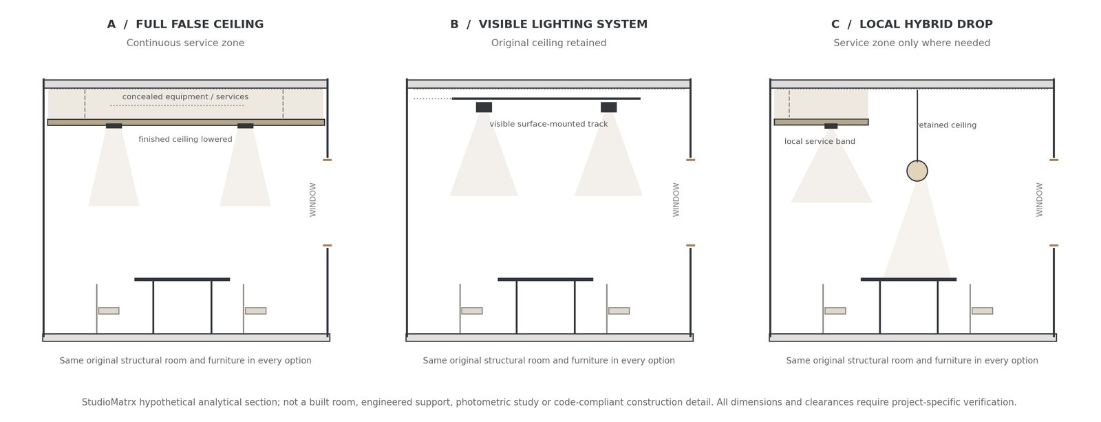
| Question to test | Full false ceiling | Visible system | Local hybrid |
|---|---|---|---|
| Where is the equipment? | Within the continuous overhead zone | Visible on or below the original soffit | Concealed selectively; other sources may be visible |
| What changes physically? | Finished ceiling plane is lowered | Ceiling volume is substantially retained | Only specified portions are lowered |
| What requires checking? | Overall depth, support and access | Fixing, supply route and fitting compatibility | Local depth, junctions and access |
| What remains unresolved here? | Actual product and service envelopes | Installation and lighting performance | Whether the partial zone is justified |
Q11. What happens when we cross-examine the two positions?
TO THE CASE FOR A FULL DROP
If a service zone is important, exactly which overhead components occupy it and how is each reached? Which of those needs truly extend across the whole room? Can the same lighting purpose be achieved by a partial zone while preserving height elsewhere? If the answer relies on a concealed source, which selected product’s technical drawing demonstrates the required depth?
A convincing response must show the services and their support, the finished ceiling line and the maintenance access in the same coordinated information. The promise of a clean ceiling below is not sufficient if the owner cannot service what sits above.
A designer advocating a full drop should be able to answer a further objection: what is the smallest intervention that could perform the same technical job? If a duct or fitting occupies only one edge of the room, why should the full ceiling move? There may be a good reason—consistent architectural proportion, continuous access or the integration of several services—but it needs to be shown, not asserted. A polished image of the complete plane does not substitute for that explanation.
TO THE CASE FOR AN EXPOSED CEILING
If preserving height is the principal advantage, where will the lighting actually mount and how will the cables run? What is the visual effect of those tracks, fittings and connections in ordinary daylight? If the room contains substantial overhead services, does leaving them visible produce an equally coherent and safe solution? Are the proposed fittings accessible without obstructing occupation?
A convincing response must show that retaining the ceiling plane is more than declining additional construction. Visible systems require real coordination, and preserving height does not automatically resolve lighting quality, service compatibility or the appearance of equipment.
A designer advocating the exposed option faces an equal challenge. Where does the electrical connection enter the room? Can the chosen surface safely carry the track or luminaire? Does the visible system interfere with fans, openings, sightlines or other equipment? If an awkward arrangement of cable conduits is required, would a small local enclosure actually improve the result? Preserving height is one benefit, but it does not absolve the proposal of technical responsibility or visual coordination.
Neither side should be permitted to speak only in ideals. The full-drop proposal must disclose the height and access consequences of concealment; the exposed proposal must disclose the visual and service consequences of keeping the slab visible. The drawings and product information should be comparable enough for an owner to understand the exchange.
Q12. What if neither a complete drop nor a fully exposed system feels right?
Then the hybrid approach deserves investigation, not as a decorative compromise but as a response to where depth is genuinely needed. A local service band may organise equipment near one wall; a limited dropped area may accommodate a particular overhead service while allowing most of the room to retain its original height; joinery or wall-based sources may relieve the ceiling of tasks that do not need to be performed there.
But hybrid construction can become another form of excess if every new ceiling step exists merely to create a novel silhouette. Each added plane should be supported by a clear reason. Ask what it contains, what it makes possible and what would be lost if it were removed. If a perimeter band has no particular lighting, access or service function, a smaller or different solution may be more appropriate.
The hybrid solution is often easiest to judge when its boundary is drawn clearly. Where does the additional plane begin, why does it stop there and how will its termination look against a wall or beam? Partial drops add edges, corners, material junctions and possible shadows; they are not visually neutral. If those junctions are aligned with genuine architectural conditions, the intervention can feel deliberate. If they float without a spatial or technical reason, the room may acquire a decorative ceiling pattern that is more conspicuous than the equipment it was supposed to accommodate.
A useful professional test is to annotate each proposed lowered portion with the specific requirement it serves—equipment depth, service route, access or planned visual effect. If no clear requirement can be written beside a band or step, reconsider that element. The exercise is not meant to eliminate expression, but to make the connection between expression and physical purpose explicit.
The hybrid is neither the automatic winner nor the midpoint of a style competition. Sometimes a complete, well-coordinated ceiling is the clearest solution. Sometimes the existing soffit should remain untouched. Sometimes additional construction belongs only in one specific part of the room. The section comparison makes those alternatives visible without ranking them in advance.
05 / TURN THE Q&A INTO A DECISION
Q13. What does each reader take away from this discussion?
For a homeowner, the next step is to request two pieces of evidence before giving approval: a section showing finished room height and a simple explanation of how fittings and drivers will be serviced. Ask to see at least one credible alternative that leaves more of the original ceiling intact. The purpose is not to reject the architect’s preferred scheme, but to understand why its additional construction is necessary.
For a professional, the task is to compare design intent with physical constraints. Establish where light must reach, which selected equipment provides it, what mounting conditions it requires, how other services share the overhead zone and how access is maintained. The false ceiling should be described as a coordinated architectural and technical choice, not simply the background to a reflected-ceiling plan.
For a small project, the three audiences can look at the same evidence from different positions. The homeowner asks about retained height, repair and everyday appearance. The designer explains the physical system through coordinated plan, section and product information. The student uses the same base drawing to test an alternative and identify uncertainty. This shared frame makes the conversation less dependent on taste. Everyone can disagree about the desired visual character while still agreeing on what construction, access and support the proposal requires.
For a student, draw one unchanging room section in three arrangements: a complete drop, the existing ceiling with visible equipment, and a local hybrid intervention. Beneath each drawing, identify one genuine benefit, one physical cost and one unknown requiring a product sheet or consultation. There is no correct visual winner. The exercise is successful when each scheme can be defended and questioned using the same room.
Q14. So, does good lighting need a false ceiling?
Sometimes the most appropriate lighting design includes one. Sometimes it does not. A false ceiling can provide useful installation depth, coordinate overhead systems and allow selected sources to recede from view. It can also consume room height, introduce more construction and place future repairs behind a finished plane. An exposed arrangement can preserve the existing ceiling and make some equipment easier to alter, yet it must still address visible hardware, fixing, supply and composition. A hybrid proposal can be precise or gratuitous depending on what actually sits within it.
The important difference is between a decision and a habit. If the scheme begins with a lowered plane simply because recessed lights are familiar, the lighting has begun to dictate the architecture. If the scheme rejects concealment as a principle, it may ignore situations in which technical coordination and visual restraint are genuinely valuable. Neither reflex constitutes a complete lighting strategy.
The most responsible answer may even change during design development. A preliminary ceiling concept might be appropriate until a selected fitting proves too deep for the intended void. An exposed arrangement might be persuasive until service coordination makes a partial band more convincing. A hybrid proposal might be refined into a full plane when several overhead needs truly coincide. Revision is not indecision; it is evidence changing a design judgment. The section should allow that possibility rather than treat any of the three categories as a principle that must be defended at all costs.
The better order is to understand the room, establish the desired light, investigate the physical system and only then decide what the ceiling must become. That approach does not end this question with a winner; it makes each answer accountable to the architecture, its use and its future maintenance.
DOCUMENTATION & TECHNICAL REFERENCES
The following primary manufacturer material illustrates available installation approaches. It is not evidence that any unspecified project has adopted a particular system or that a listed product meets another manufacturer’s requirements. Final dimensions, access and compliance must be verified for the selected project.
ERCO — Recessed luminaires: product-specific cut-outs, required recess depth and driver envelope. Open technical document
ERCO — Track and singlets: surface-mounted, recessed and suspended options. Open technical document
ERCO — Planning Aid for Tracks (2025): installation variants and component coordination. Open technical document
Knauf India — A@TCH Premium Access Panels, technical data: service access in concealed ceilings. Open technical document
Source note: Manufacturer documents demonstrate possible systems, not universal installation dimensions or legal compliance. All comparisons are schematic and should be checked with the selected products and applicable requirements.