
Where the Sun Lands
Designing daylight, shade and night light for rooms in a warm climate
A window is not a hole in a wall. It is a decision about where the sun will land, how long it will stay, and what the room will feel like while it does. This article follows one question from the sky to the floor and into the night: how do we decide where light goes?
1. Light is a material we cannot touch
We usually meet light in architecture as an effect: a shaft of sun in a church, the glow of a lamp on festival night. As a student drawing plans and sections, I have found it more useful to treat light as something designed, with dimensions and angles, like a beam or a slab. A beam is sized before it is cast. A patch of sun can be sized before the wall is built.
This article keeps to one subject, Daylight in a warm climate, which describes most of India. It moves in the order a designer would work. First the sun's geometry (sections 2 to 4), then what happens inside the room (sections 5 to 8), then the same room after dark (section 9), and finally what happens when the room is asked to celebrate (section 10). Every section uses a number or a drawing, because a claim about light is only useful if someone can check it on a plan.
The theme of this issue is Light & Celebration, and I think the two belong together for a practical reason. A celebration rarely begins with decoration. It begins with a place that was already prepared to receive light: a court open to the sky, a parapet wide enough for a row of lamps, a wall that can hold a pattern. Prepare the place well, and a few lamps are enough.
2. Reading the sun
Two angles describe the sun. Altitude is its height above the horizon. Azimuth is its compass direction. Both depend on the latitude of the site, the date and the time of day. For design, the most useful single number is the altitude at solar noon, because it sets the longest reach of direct sun into a room and the shortest shadow outside. At solar noon it can be found with one line of arithmetic:
Noon altitude = 90° − | latitude − declination |
The solar declination moves between +23.45° (21 June) and −23.45° (21 December). Table 1 applies the formula at 13°N, a typical south-Indian latitude, and Figure 1 plots it through the year.
Table 1. Solar noon at 13°N
| Date | Declination | Noon altitude | Where the noon sun is |
|---|---|---|---|
| 21 December | −23.45° | 53.5° | South of overhead |
| 21 March / 23 September | 0° | 77.0° | South of overhead |
| 21 June | +23.45° | 79.5° | North of overhead |
| About 25 April and 18 August | +13° | 90° | Directly overhead |
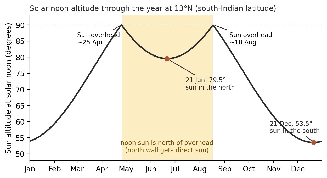
Three observations follow from the chart, and each change how a plan should be drawn.
The roof takes most of the sun. For much of the year the sun is high, so the roof and the terrace receive the heaviest radiation. Walls matter, but the roof matters more.
Both north and south walls see direct sun at some point. The noon sun swings from the south wall to the north wall and back, so neither side can be treated as permanently shaded. The north wall is easy only for part of the year.
East and west are the difficult sides. The morning and evening sun is low, and a horizontal overhang does very little against it. This is where most overheating in ordinary buildings begins.
These are noon values only. For real decisions, the sun path for the actual site should be checked in a sun-path viewer or a shadow study in the drawing software, since obstructions such as neighbouring buildings and trees change everything.
3. Orientation: choosing the walls that carry the openings
Orientation is the cheapest design decision there is, because it costs nothing to draw the plan one way instead of another. Figure 2 summarises the strategy I would start from for a habitable room. It is a starting point, not a rule. A good site view or a prevailing wind can override it.
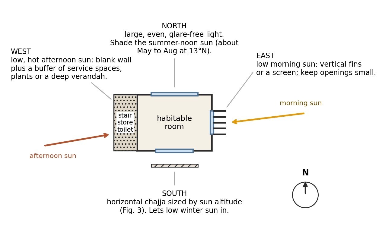
North: large openings are comfortable here. The light is even and low in glare. At 13°N the summer noon sun does reach this wall, so it still needs a modest shade.
South: a horizontal projection (a chajja) can be sized accurately, as section 4 shows. It lets the low winter sun in and keeps the high sun out.
East: accept some morning sun, but break it up with vertical fins or a screen and keep the openings small.
West: keep the wall blank or lightly perforated and place stairs, stores, toilets or a deep verandah on this side. These spaces absorb the afternoon heat before it reaches the rooms people live in.
4. Shading by calculation
Horizontal projections: the chajja
A horizontal overhang is designed with the vertical shadow angle (VSA), the angle of the sun measured in the vertical plane at right angles to the wall. For a wall that faces the sun squarely, as a south wall does at noon, the VSA equals the sun's altitude. The depth of projection needed to shade a window of height h is then:
P = h ÷ tan (VSA)
Figure 3 is a section through a south wall at 13°N. The window is 1.5 m high and the chajja is 0.6 m deep. The calculation for the three rays drawn is below.
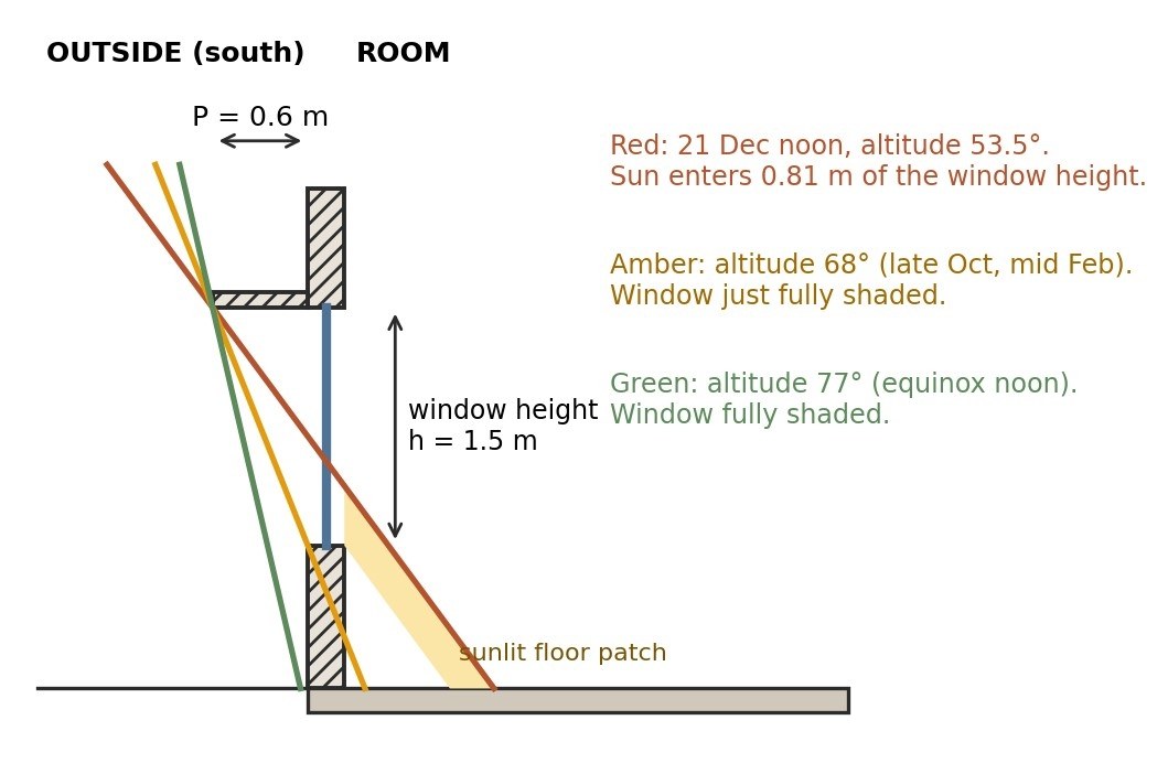
At the equinox noon (77°), the shadow from a 0.6 m chajja is 0.6 × tan 77° = 2.6 m deep. The 1.5 m window is entirely shaded.
At the limit angle, P = 1.5 ÷ tan 68.2° = 0.60 m, so 0.6 m is exactly enough to shade the full window whenever the noon altitude is 68° or more. At 13°N that is from about mid-February to late October.
On 21 December (53.5°), the same chajja shades 0.6 × tan 53.5° = 0.81 m of the 1.5 m window. The remaining 0.69 m is sunlit and the beam reaches about 1.2 m into the room.
So, the chajja is not simply a device for keeping sun out. By choosing P, the designer chooses which months the sun is welcome. In moderate climates the winter sun is pleasant. In hotter climates the same chajja would be made deeper. Making P large enough to shade this window completely on 21 December would take P = 1.5 ÷ tan 53.5° = 1.11 m, a deep projection that would also darken the room for the rest of the year. Every metre of overhang is a trade-off between heat and light.
Vertical fins for east and west
Low sun from the east or west arrives at a large horizontal shadow angle (HSA), measured in plan between the sun's direction and the normal to the wall. A vertical fin of depth D shadows a width of D × tan (HSA) along the wall. Fins spaced at S therefore close off the opening when:
D ≥ S ÷ tan (HSA)
For an HSA of 60° and fins at 0.6 m spacing, D must be at least 0.6 ÷ 1.73 = 0.35 m. Because the sun's direction changes through the afternoon, a fin sized for one hour is only partly effective at another. This is why west-facing screens are usually combined with a blank wall, rather than relied on alone.
Shade the glass from the outside
External shading stops solar heat before it reaches the glass. An internal curtain or blind only stops the light, and the heat stays inside. Glazing also matters. Two properties are worth checking on every specification sheet: visible light transmittance (VLT), which says how much daylight passes, and the solar heat gain coefficient (SHGC), which says how much solar heat does. For a warm climate, the aim is a high VLT with a low SHGC, so that the VLT/SHGC ratio is above 1.
5. How deep does daylight travel?
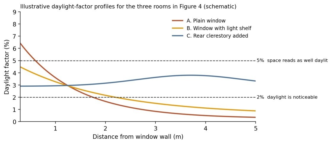
A window lights the room unevenly. The bright zone near it fades quickly with distance. Designers measure this with the daylight factor (DF), the ratio of the illuminance at a point indoors to the illuminance outdoors under an overcast sky, expressed as a percentage. Under the standard overcast design sky of about 10,000 lux, a DF of 2% gives roughly 200 lux and a DF of 5% gives about 500 lux. As a widely used guide, an average DF near 2% reads as partly daylit and near 5% as well daylit.
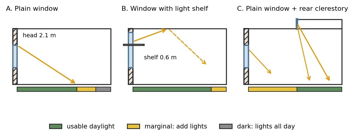
A rule of thumb for a side-lit room is that useful daylight reaches about 1.5 to 2 times the window head height from the window wall. A light shelf, which is a horizontal reflector at about door height, bounces light up to the ceiling and extends this reach. A clerestory at the rear adds light to the zone that the window cannot reach. Figures 4 and 5 compare the three arrangements for the same 5 m deep room.
A worked example
Take a room 4.0 m wide and 5.0 m deep (20 m²), with a window 2.0 m wide, a sill at 0.9 m and a head at 2.1 m. The glazed area is 2.0 × 1.2 = 2.4 m², or 12% of the floor area. That passes the usual byelaw tests, which commonly ask for an opening area between about one-tenth and one-sixth of the floor area, depending on the authority and the room type. The local byelaw should always be checked.
Daylight reach is 1.5 to 2 × 2.1 m = 3.2 to 4.2 m. The last metre or so at the back of the room is therefore dim. Adding a light shelf at 2.1 m with a clear strip above it up to 2.8 m raises the effective head to 2.8 m. The reach becomes 4.2 to 5.6 m, so the whole room is covered. The cost is a thin strip of glass and a 0.6 m shelf. This is a design improvement made with a 5-minute calculation.
What the surfaces do
The room itself is a light fitting. A white ceiling reflects about 70 to 80% of the light that strikes it, light walls about 50 to 60%, and a dark floor perhaps 20%. Painting the ceiling and the wall opposite the window white often adds more usable light than enlarging the window, and does not add heat. A deep, splayed window reveal, with the sides angled outward, also softens the contrast between the bright sky and the dark wall around it, which is the cause of most glare.
6. Filtering light: the jaali
A solid wall with a hole lets light and view come through together. A jaali (a perforated or latticed screen) separates the two. It lets in brightness without a view of the outside, cuts the contrast between a bright sky and a dark wall, and passes breeze. The idea is old in Indian architecture: the stone screens of Sidi Saiyyed Mosque in Ahmedabad (1573), and the 953 small windows of the Hawa Mahal in Jaipur (1799), are famous examples. In the twentieth century Laurie Baker used brick Jaali’s in the 1970s at the Centre for Development Studies in Thiruvananthapuram, using the same principle with ordinary bricks laid with gaps.
The physics is simple. Figure 6 shows a single opening of diameter or height d in a screen of thickness t. Rays within a limit angle of the normal, where tan θ = d ÷ t, can pass straight through. Steeper rays strike the sides of the opening and are absorbed or reflected. A brick jaali with 100 mm holes in a 230 mm thick screen (a one-brick wall) has a limit angle of a tan (100 ÷ 230) = 23°. High sun is blocked while sky light still gets through. For the circular holes in the panel on the left, the open area is π × 50² ÷ 150² = 35% of the panel.
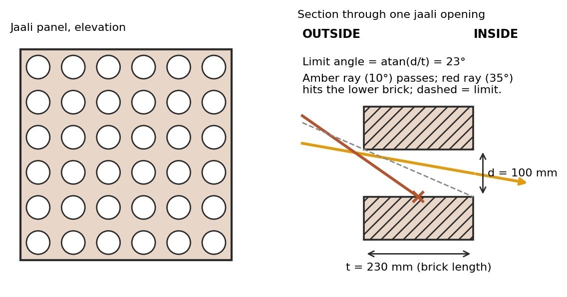
This gives the designer two controls. Thickness decides which sun angles are blocked, and open area decides how much light is passed. A thin metal screen with the same holes would let almost all angles through, which is why modern perforated panels are often layered, or set back from the glass.
7. Four buildings that treat light as structure
None of these buildings is about lighting products. In each, light is the reason the form exists.
The Pantheon, Rome (c. 125 CE). The only opening is a circular oculus about 8.2 m wide at the top of the dome. A disc of sun crosses the coffered dome and the floor through the day, so the building behaves as a slow clock. All the light comes from one source in one place, and everything else in the building is arranged around it.
Church of the Light, Ibaraki, Japan (Tadao Ando, 1989). A cross-shaped slit is cut through a concrete wall behind the altar. The room is kept dark on purpose, so the narrow cross reads as intense brightness. It shows that an opening can work by contrast alone, with no size or area.
Indian Institute of Management, Ahmedabad (Louis Kahn, designed from the early 1960s). Brick walls are pierced by large circular and arched openings and deep reveals. The thickness of the wall does the shading, much like the jaali in section 6. Direct sun is held at the face of the wall, and soft light falls in the corridors.
Millowners' Association Building, Ahmedabad (Le Corbusier, 1954). A brise-soleil of deep concrete fins shades the façades, with the depth of the fins set by the sun angles. It is a large-scale version of the calculation in section 4, applied as the composition of the façade.
8. A worked plan: a drawing studio by daylight zones
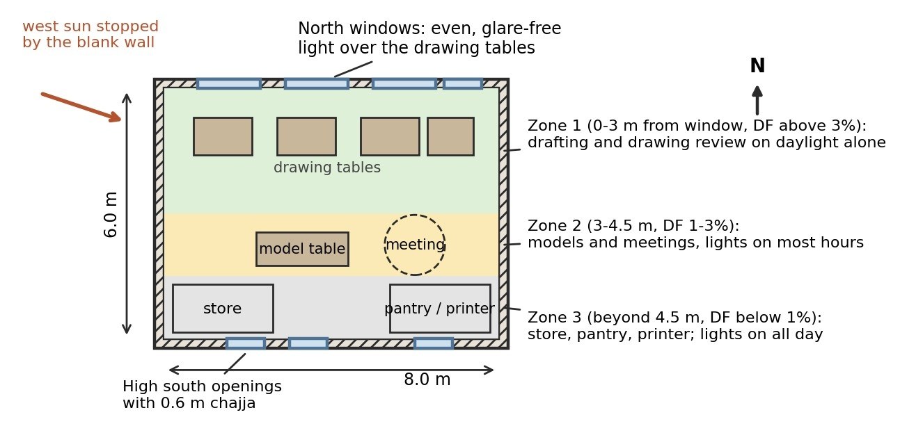
Daylight can be used as a planning tool, not just a finish. Figure 7 is a drawing studio of 8.0 m × 6.0 m (48 m²), the kind of room an office like ours might use. The long north wall carries four windows with a total width of 5.4 m and a height of 1.2 m (sill 0.9 m, head 2.1 m), a glazed area of 6.5 m², which is 13.5% of the floor area.
The room is divided by distance from the window into three zones. Work that needs the best light, such as drafting, goes in zone 1, where daylight alone is enough for most of the working day. Models and meetings, which tolerate moderate light, go in zone 2. Stores, pantry and printer, which need little daylight and benefit from being away from glare, go in zone 3. The west wall is solid, and the south wall has high small openings with a 0.6 m chajja for cross-ventilation and a little reflected light. Nothing in this plan required any extra cost. It is only the order in which the furniture was placed.
9. After dark: artificial light as a continuation
When the sun sets, the same room needs a second light system. The best of these systems continues the logic of the daytime plan, instead of replacing it. Good lighting works in layers: ambient light for the whole room, task light where the work is, and accent light for the surfaces that give the room character.
Table 2. Typical design illuminance by space and task
| Space / task | Typical target (lux) | Note |
|---|---|---|
| Corridors, stairs | 100 | Raise at the stair nosing for safety |
| Living room, general | 100 to 200 | Add task light for reading |
| Kitchen, work surfaces | 300 | Light the counter, not only the room |
| Study, reading | 300 to 500 | Shielded source, no glare on the page |
| Office or studio, general | 300 to 500 | Supplement with desk lights |
| Technical drawing, detailing | 500 to 750 | High uniformity, low glare |
| Space / task | Typical target (lux) | Note |
These figures reflect common practice (IS 3646 and international guides such as EN 12464-1).
They should be checked against the current National Building Code for each project.
Table 3. Light source characteristics worth reading on a data sheet
| Property | Typical range | Why it matters |
|---|---|---|
| Luminous efficacy | 80 to 130 lm /W for LED | Sets the electrical load for a given light level |
| Colour temperature (CCT) | 2700 to 3000 K warm; 4000 K neutral | Warm for rest and celebration, neutral for work |
| Colour rendering (CRI, Ra) | 80 or more; 90 or more for colour work | Materials and drawings look true |
| Glare rating (UGR) | 19 or less for drawing and office rooms | Controls discomfort glare from luminaires |
Sizing it: the lumen method
The number of luminaires for an even level of light on a work plane follows from the lumen method:
N = (E × A) ÷ (F × UF × MF)
where E is the target illuminance in lux, A the floor area in m², F the lumens of one luminaire, UF the utilisation factor (the share of lamp lumens that reaches the work plane) and MF the maintenance factor (allowing for dust and ageing). For the studio of section 8, take E = 500 lux for drafting, A = 48 m², and a 600 × 600 mm LED panel of 3,600 lm, with UF = 0.55 and MF = 0.8:
N = (500 × 48) ÷ (3,600 × 0.55 × 0.8) = 15.2, so use 16 panels
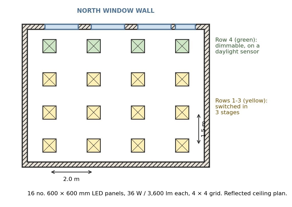
Sixteen panels fit a 4 × 4 grid at 2.0 m by 1.5 m spacing, as in Figure 8. With the ceiling at 3.0 m and a work plane at 0.75 m, the mounting height is 2.25 m. The spacing-to-height ratio is 2.0 ÷ 2.25 = 0.9, which is within the usual limit of about 1.0 for panels of this type, so the light will be even.
At 36 W each, the 16 panels draw 576 W, or 12 W/m², which is on the high side for an office. That is why the next step matters. The row nearest the north windows (row 4 in the figure) is put on a daylight sensor or a dimmer, because that is where daylight is strongest. The other three rows are switched in stages. Used in this way, artificial light stays low until the daylight falls away.
10. Light and celebration: designing the temporary layer
A festival changes a building's light without changing the building. Lamps are added along a parapet, strings are hung from a verandah, the courtyard is lit, and the same rooms look different. Figure 9 shows a simple courtyard house by day and by night. By day, the court is the main source of light. At night, the same court becomes a stage for a lower, warmer set of lights in layers.
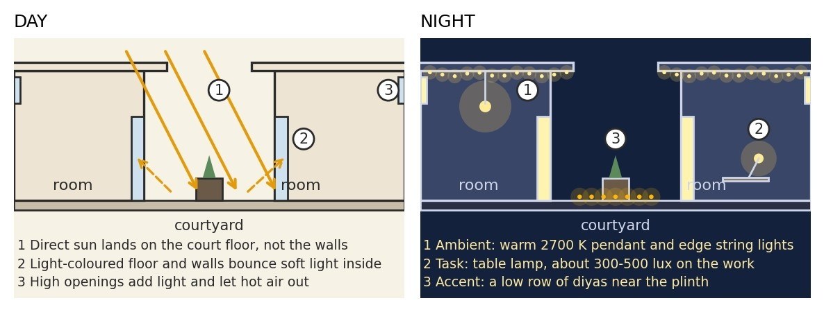
It is worth asking how much light a festival adds. A single oil lamp (a diya) gives roughly the light of a candle, which is about 1 candela, or 12 lumens. One hundred lamps therefore give around 1,200 lumens, about the same as one 12 W LED bulb. Yet a row of lamps feels far brighter than that. The reason is contrast and adaptation. The eye, after dark, adjusts to low levels, and small warm points against a dark surround, near the ground and reflected in water or brass, read as brilliant. A celebration is therefore a lesson in how little light is needed when it is placed correctly. The design implications are practical:
Give the lamps a place. Niches, plinths, steps and wide parapets are positions for lamps. A parapet of 150 to 200 mm width and a non-combustible finish hold a row safely. Without a surface of this kind, lamps end up on the floor.
Light low and warm. Keep festival light below eye level and near 2700 K, with no bare bright sources in the line of sight.
Provide for the temporary layer in the permanent building. Weatherproof sockets, hooks, and a few conduits at parapet level cost little at construction, and avoid cables stapled across a façade every year.
Respect fire safety. Keep open flames away from cloth, torans and dried garlands. Where a crowd or a high building is involved, use LED lamps or a mix of both.
Let the day layer do its part. A light-coloured court floor and walls (Figure 9, left) carry the evening glow too, since they reflect the lamps back into the rooms.
11. Conclusion
Light looks like the most intangible part of architecture, and it is also one of the most calculable. A noon altitude, a projection depth, a head height, a thickness-to-opening ratio and a lumen count are enough to decide most of what a room will feel like. The numbers do not remove the poetry. They are what allow it to be repeated on purpose, in the dark brick arches of Ahmedabad and in the narrow cross at Ibaraki.
For celebration the lesson is the same. The lamps on a parapet do not make the festival. The parapet, the court and the colour of the walls make a place in which a few lamps are enough. The best festive light begins as good daylight design, done early, in plan and section.
References
Bureau of Indian Standards. National Building Code of India 2016, Part 8 (Building Services), Section 1: Lighting and Natural Ventilation.
Bureau of Indian Standards. IS 3646 (Part 1): Code of Practice for Interior Illumination.
Bureau of Energy Efficiency. Energy Conservation Building Code (ECBC) 2017 and EcoNiwas Samhita 2018 (residential envelope code).
Koenigsberger, O. H., Ingersoll, T. G., Mayhew, A. and Szokolay, S. V. Manual of Tropical Housing and Building: Climatic Design. Orient Longman, 1973.
Olgyay, V. Design with Climate: Bioclimatic Approach to Architectural Regionalism. Princeton University Press, 1963.
Brown, G. Z. and DeKay, M. Sun, Wind and Light: Architectural Design Strategies. Wiley.
Tregenza, P. and Wilson, M. Daylighting: Architecture and Lighting Design. Routledge, 2011.
Littlefair, P. Site Layout Planning for Daylight and Sunlight: A Guide to Good Practice (BR 209). Building Research Establishment.
Millet, M. S. Light Revealed: Architecture, Daylight, Artificial Light and the Art of Lighting. Wiley, 1996.
Author Bio:
Pramod P
SJMIT College, Chitradurga
- SJMIT College, Chitradurga