
A Concealed Cove Light
The Light You See Is Not the Source You See
A concealed cove light is often judged by the simplicity of its finished appearance. A continuous band of light travels across a ceiling or upper wall while the luminaire remains outside the viewer’s direct sight. The ceiling appears to glow, with no visible fitting interrupting its surface. At first glance, this seems like one of the simplest lighting details to execute. It may consist of a recessed edge, a linear source, and a painted receiving surface. Yet the finished effect depends on the physical relationship between components usually hidden after construction.
Consider two completed rooms with apparently identical perimeter coves. Both use linear LED lighting concealed behind a projecting ceiling edge. In the first, the illuminated ceiling shows a relatively continuous band of light, with no individual LED points visible from the principal seating positions. In the second, the illuminated region is interrupted by brighter patches, an exposed portion of the source near a corner, and a sharp line where the light stops. The difference may not be caused by the source’s overall brightness. It may result from a small change in source position, the geometry of the concealing edge, the mounting channel arrangement, or the condition of the receiving surface.
This distinction matters because a concealed cove is not merely an electrical product installed inside a recess. It is an assembly where the construction, luminaire, and surface work together. The source emits light, the recess determines where it can travel, the concealing edge controls what an observer can see, and the nearby ceiling or wall returns some incident light into the room. If these relationships are poorly resolved, concealing the equipment may produce a less satisfactory effect than leaving the luminaire visible.
This becomes particularly apparent when the selected lighting system is changed after the architectural section is finalised. A product with a different profile height, optical cover, or distribution may no longer fit the originally drawn geometry. Its light may strike a different part of the receiving surface, or the front edge may obstruct too much of the intended output. The drawing may appear unchanged, but the conditions needed for the desired result have changed.
Manufacturer guidance recognises these problems. Philips Colour Kinetics explains that linear cove lighting involves difficult questions of output consistency because sources often sit close to the illuminated surface, leaving limited distance for light to spread and mix. Its installation literature also treats luminaire position, setback, aiming and cove geometry as connected decisions. The visual continuity of a concealed installation therefore cannot be judged through the lamp’s wattage or appearance alone.
For architects, the task is to make a detail that can be built and inspected. For homeowners, the concern is whether the finished installation will produce the intended light without exposing its equipment or becoming unnecessarily difficult to maintain. For students, the challenge is to understand how a relatively small alteration to a section can change the visible result across an entire room.
The central construction question is straightforward: How can a luminaire remain hidden from the intended viewpoints while still delivering enough light to the correct architectural surface? The answer begins with the section, not with selecting an LED strip.
Start With the Section
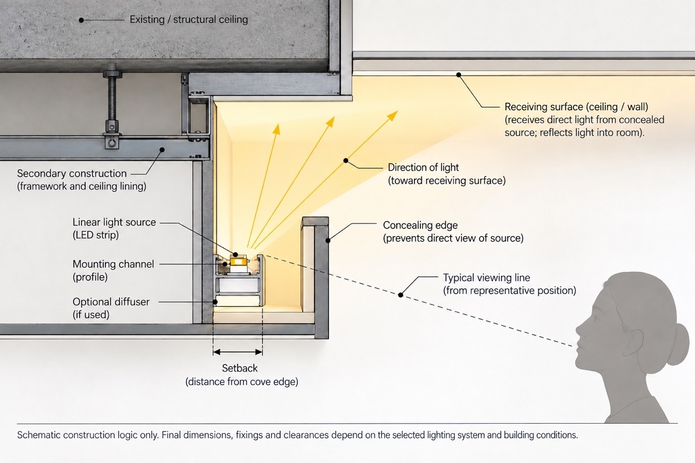
A reflected ceiling plan can establish the location of a concealed lighting run, show where it turns corners, and identify which parts of the room contain the system. However, the plan alone cannot explain why the light source remains concealed or how its output reaches the ceiling. These relationships become visible in section, where the structural ceiling, secondary construction, recess, source, concealing edge, and receiving surface can be studied together.
Imagine a perimeter cove formed along the upper edge of a room. A secondary construction element creates a horizontal ledge or recessed channel below the original ceiling. A linear luminaire sits within that space and directs light toward the upper ceiling or wall. The front edge conceals the source from selected viewing positions, but the opening above must remain large enough to allow useful light distribution. The section must resolve both functions. Concealment without a useful light path is not a successful detail.
The first distinction is between the building structure and the additional construction used to create the cove. An existing concrete slab, roof structure, or other structural ceiling is not necessarily the surface to which every component should be attached. The suspended framework, board lining, joinery, or purpose-designed construction system may establish a separate mounting arrangement. The actual load path and permissible fixings depend on the substrate and product. A schematic section can identify these elements but must not imply that one generic fixing method suits every project.
The second distinction concerns the visible boundary and the receiving surface. The concealing edge blocks the direct view of the luminaire. The receiving surface is the ceiling or wall where the intended illumination appears. They may be physically close but perform different functions. Raising the concealing edge can change source visibility; repositioning the light source can change distribution on the receiving plane. Both alterations may be necessary but cannot be considered independently.
A useful architectural section identifies the source position, its support or mounting profile, the visible fascia or lip, the opening through which light leaves the recess, and the intended receiving surface. It should also identify the approximate light direction, the viewing position checked, and the proposed route for electrical services. If a diffuser is part of the selected system, it should be indicated as a separate component rather than assumed included in every linear luminaire.
The section should not begin with dimensions borrowed from an unrelated project. A fixed distance between the source and recess edge cannot guarantee concealment or illumination quality in every room. Different luminaires have different physical dimensions and optical distributions, while viewing positions, ceiling height, and surface finishes also vary. The first drawing is therefore a coordination drawing: it establishes which relationships must be resolved before final construction dimensions can be approved.
The Recess Must Work as a Buildable Assembly
Once the section establishes the basic relationship, the recess becomes the first physical element requiring detailed coordination. It is easy to regard the space behind the concealing edge as just an empty channel for the LED strip. In reality, it must accommodate the selected lighting assembly, provide a suitable mounting surface, preserve the intended light path, and allow installation without damaging or distorting the finished construction.
Assess the available space against the complete luminaire assembly, not just the emitting element's dimensions. A linear source may require a profile, optical cover, connectors, cable entries, end components, and fixing accessories. Some arrangements use an integrated luminaire rather than a separate strip-and-profile assembly. You cannot substitute these systems without checking the space available inside the recess.
A narrow recess can create problems before electrical work begins. The profile may sit too close to the concealing edge, or there may be insufficient room to orient the source towards the intended surface. The mounting arrangement may be difficult to secure within the available space, and the cable entry may conflict with the supporting framework. Enlarging the recess is not always the solution. If the added construction changes the opening or creates a deeper obstruction, it may worsen the light distribution.
Construction tolerance becomes significant when a cove extends along several metres of wall. A slight deviation in the supporting framework may produce an uneven fascia or mounting ledge. Under ordinary room lighting, that discrepancy may be difficult to notice. Once the concealed source illuminates the neighbouring surface, a variation in the lip or receiving plane becomes more visible. The cove can unintentionally reveal inaccuracies in the work intended to conceal the equipment.
Corners introduce another level of coordination. The internal construction must continue without obstructing the source or forcing the profile into an unsuitable position. Where one straight run meets another, the design must establish how components terminate or turn, how wiring is routed, and whether an interruption in the illuminated band is acceptable. A continuous drawn line around a room perimeter does not prove that a selected product can be assembled in that form.
The construction sequence matters as much as the final geometry. Establish the supporting framework before closing the internal mounting surfaces and finishing layers. Coordinate electrical provisions before access becomes restricted. Surface finishing may need to reach a suitable standard before the luminaire is mounted, depending on the selected assembly and the manufacturer’s instructions.
This is also the point when a design team should identify which parts of the cove will remain accessible and which will become permanent construction. A fixed gypsum-board fascia, a removable cover, and a detachable luminaire are not equivalent components. Their removal and replacement requirements differ, and the construction should reflect that.
The architect should treat the recess as a small architectural assembly with its own construction sequence, tolerances, and maintenance conditions. The final line of light depends partly on the accuracy and coordination of work that will be almost completely invisible once the room is finished.
Three Source Positions, Three Different Outcomes
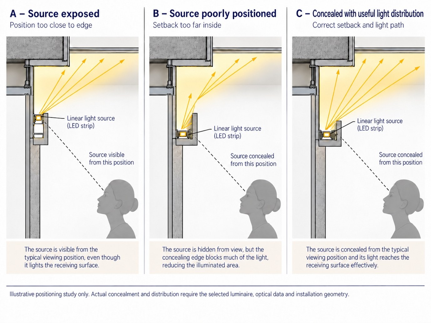
The most instructive test of a concealed cove is to hold its architectural geometry constant and move the source within it. This isolates the effect of source position from changes to the ceiling or concealing edge. The comparison should examine what the observer can see and where the intended light travels.
In the first condition, the luminaire sits too close to the visible edge or projects beyond the intended sightline boundary. It may illuminate the ceiling effectively, but from a principal occupied position, the observer can see part of the emitting surface. What was intended as indirect light becomes partly direct light. The exposed source may draw attention to the channel, interrupt the architectural effect, or create an uncomfortable bright region depending on its luminance and surroundings.
In the second condition, the luminaire has been moved farther behind the edge. The emitter may now be hidden from the selected viewpoint, but the fascia or internal construction obstructs much of the light intended to reach the ceiling. The illuminated area may become narrower, begin abruptly, or display a brightness concentration closer to the recess. The source is concealed, but the distribution may no longer achieve the desired result.
The third condition represents an arrangement where the selected luminaire remains concealed from the representative viewing position while its useful output reaches the receiving surface. That condition is not established merely by placing the source halfway between the first two positions. The correct relationship depends on the luminaire’s optical characteristics and the actual recess geometry. A directional source may require a different position or orientation from a broad-distribution source, even when both fit inside the same construction.
This is where the terms setback, standoff, and aiming need careful use. Depending on the manufacturer, setback may describe distance from the cove opening, while standoff refers to separation from an internal surface. Aiming describes the luminaire's direction or optical output. These are different variables, and each must be dimensioned or represented clearly in the relevant drawing rather than described by one ambiguous instruction to place the strip farther inside.
Philips Color Kinetics discusses these relationships in its technical guide to cove lighting. The guide explains that luminaire standoff, setback and aiming influence the intensity and uniformity of light leaving the cove. It also identifies mixing distance as important, particularly because individual LED emitters can produce unwanted bright regions or visible variation when the receiving surface is too close. These are system-dependent relationships, not general dimensions that can be copied into every construction section.
The most reliable approach is to develop several source-position alternatives using the same architectural section and selected luminaire. Check their suitability through photometric information and, where visually important, a representative full-scale sample. The purpose is to determine which relationship balances concealment and useful distribution.
What a Real Manufacturer’s Component Changes
A concealed cove becomes more understandable when the discussion moves from an unspecified LED strip to an actual manufacturer’s component. The selected product does not automatically define a complete construction detail, but its published information identifies the physical and technical conditions it must accommodate.
One useful example is the KLUŚ POLI extrusion, reference A07176. The manufacturer identifies it as an aluminium extrusion intended for applications including architectural niches and perimeter coves. Its published technical data gives an overall profile width of approximately 26.1 mm and a height of 7 mm, with a suitable LED mounting width of approximately 11.2 mm. The manufacturer’s information also describes adjustable lighting orientation, with adjustment capability up to 90 degrees, and assembly using dedicated accessories that enable the lighting component to be installed and removed by a snap-in arrangement.
These dimensions belong specifically to the POLI extrusion. They do not describe the necessary depth or height of the complete architectural cove. The final arrangement must also accommodate the selected LED strip, cover, mounting bracket, electrical connections, and other required components. The manufacturer’s published profile width is a product fact, not a recommended recess dimension.
The associated POLI mounting bracket, reference C24112C10, clearly illustrates the relationship between the luminaire and the building. The manufacturer’s description identifies a dedicated bracket intended for installation in architectural niches, supporting adjustable orientation and removal of the lighting component. This means the system is not simply a loose LED strip placed behind a fascia. Its intended mounting and adjustment method forms part of its construction logic.
The specification sheet also lists compatible covers with different optical characteristics. The HS-11 cover, for instance, is listed in clear and frosted options, with published material transmittance figures of approximately 88 percent and 59 percent respectively. These figures describe the covers under the manufacturer’s product specifications. They do not mean a completed installation will deliver precisely 88 percent or 59 percent of its light to the ceiling, because the optical behaviour of the assembled source, recess, and receiving plane is more complex.
The comparison demonstrates why an optical cover should not be selected merely because it appears transparent or translucent. It can change the visible appearance of LED points and the amount and character of light passing through the assembly. A cover that helps conceal individual emitters may also affect output and distribution. The design team must evaluate that change using the chosen combination of components rather than assuming a diffuser always improves the result without consequence.
The manufacturer’s specification also identifies limits and compatibility information for LED strips used with the extrusion. That information matters for selecting the strip and its associated electrical equipment, but it should not be interpreted as permission to install any strip that physically fits. The actual components must be mutually compatible and appropriate to the intended application.
For the architect, the manufacturer information raises measurable questions that a generic schematic cannot resolve: whether the complete assembly fits, whether it can be aimed, whether its mounting method fits within the recess, and how its cover changes the emitted light. For the contractor, it begins to establish a method of installation and removal. For the homeowner, it reveals why two visually similar concealed lighting details may contain quite different systems behind their finished edges.
The POLI example is a documented component study, not a claim that StudioMatrx has installed or tested this product. It is included to demonstrate what real manufacturer data contributes to the architectural drawing. Final selection and installation must follow the applicable instructions for the particular assembled product and its accessories.
Technical documentation: KLUŚ POLI extrusion A07176, manufacturer’s product specification and compatible accessories. The component dimensions and cover transmittance values in this section apply only to the identified product.
The Profile, LED Source and Electrical System Must Agree
Once you identify a suitable physical component, coordinate the remaining lighting system with it. A mounting profile may support the source and provide a consistent installation arrangement, but the profile alone does not determine the quality of illumination, electrical compatibility, or thermal behaviour of the completed installation.
The emitting element may be an LED tape within an extrusion or part of an integrated linear luminaire. These arrangements can differ in optical design, electrical requirements, available lengths, connection systems, and servicing procedures. A separate LED tape may require a compatible power supply and control equipment, while some integrated systems contain their own driving and connection arrangements. Determine the driver and power connection location from the exact selected product, not from a generic linear fitting.
The position and spacing of individual emitters can influence the visible result when the source sits close to the receiving surface. If the light doesn't have enough distance to spread and overlap, the ceiling may show individual bright points, a repeated pattern, or local brightness changes. A suitable optical cover or different mounting position may reduce these effects, but the relationship must be checked for the complete assembly. The term continuous LED strip does not guarantee a continuous illuminated ceiling.
Continuity within one length differs from continuity across several lengths. A long perimeter installation may require multiple segments. Connections between segments can introduce physical gaps, while the electrical arrangement can influence output consistency along the run. The proposed installation should identify each segment's location, the intended connection method, and any manufacturer limits on permissible connected length or power supply arrangements.
Where low-voltage LED tape is used, voltage drop can become relevant over longer wiring or tape runs. The actual significance depends on electrical design and component specifications. Assess it using the product’s technical data rather than relying on a universal instruction to feed every strip from one end or both ends. Different manufacturers provide different allowable arrangements.
Colour consistency deserves similar attention. Two sections of a cove may appear slightly different even when they have nominally identical colour-temperature labels. Manufacturing consistency, selected product family, operating conditions, and controls can all influence the appearance of adjacent sources. Philips colour Kinetics identifies colour consistency and blending of individual LED output as important challenges in linear concealed lighting. A project requiring a continuous-looking illuminated surface must consider these characteristics before installation.
Thermal requirements must be treated as product-specific. An LED system's compact size does not mean it can operate safely in any enclosed recess. The luminaire, driver, and associated components have defined environmental and installation conditions. Verify adequate mounting, clearances, and heat dissipation using the relevant manufacturer instructions. An aluminium extrusion should not automatically be assumed to provide sufficient thermal management for every LED strip.
Electrical coordination and lighting appearance are connected. A visually continuous cove can still contain incompatible equipment, inadequate wiring, or inaccessible components. Conversely, a technically compliant lighting system can produce an unsatisfactory visual result if its source position, optical cover, and receiving surface are poorly coordinated.
The objective is to assemble one verified system in one suitable architectural detail. Selecting individual components from separate catalogues without checking their combined requirements does not ensure the completed cove will work as intended.
The Receiving Surface Is Part of the Lighting System
The final visible effect of a concealed cove usually comes from beyond the recess itself. Light leaves the hidden source, reaches the ceiling or upper wall, and returns into the occupied space. That receiving surface is therefore an active part of the lighting arrangement, even if it contains no electrical equipment.
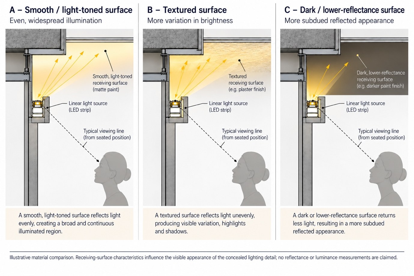
Consider three surfaces illuminated by the same concealed source from the same position. The first is smooth and light-toned, the second textured, and the third has a darker finish. Their visible appearance may differ substantially because each surface reflects and redistributes incoming light differently. The first may produce a more evenly lit region. The textured surface may reveal highlights and shadows from its relief. The darker surface may return less light towards the room under comparable conditions.
These examples are not a universal ranking of materials. A light-toned surface can reveal finishing defects if illuminated at an angle that makes them conspicuous. A textured surface can produce an intended architectural effect, while a dark surface may be appropriate where a more restrained illuminated appearance is desired. The question is whether the material response matches the design intention.
Construction quality becomes particularly visible when light arrives close to the receiving surface. A ceiling that appears smooth under general illumination may reveal differences in plastering, joint treatment, or paint finish when illuminated from a concealed perimeter source. The lighting can make slight waviness or uneven surface transitions more noticeable, especially along an extended run.
The contractor needs to understand which surfaces will be visually emphasised before completing the finish. The receiving plane should not be treated as an ordinary background whose condition can be assessed independently of the planned lighting. Finishing samples or early mock-ups may be appropriate where a long, uninterrupted illuminated ceiling is central to the architectural effect.
Junctions require particular care. A ceiling may meet an adjoining wall, change level, or terminate at a recess. Light can behave differently near these intersections because the receiving surface changes shape. The illuminated band may appear to narrow, concentrate, or end abruptly. In such cases, the cause may be the surface architecture rather than a fault in the linear source.
A useful construction review should connect the source location to the finish of the receiving plane. If an uneven band appears after installation, the team should not immediately assume the LED strip is defective. The source, its optical distribution, surface geometry, and finish all need consideration.
This distinction is valuable because it prevents inappropriate corrections. Increasing light output may make an unwanted surface defect more visible. Moving the source may reduce one highlight but create an obstruction elsewhere. Replacing the diffuser may alter the emitter’s appearance without resolving an uneven receiving surface. A successful correction depends on identifying the cause.
A Concealed Source Must Be Tested From the Room
A source may appear properly concealed in an architectural section and still become visible from another part of the completed room. A conventional detail drawing usually represents one section through the construction, but occupants experience the space from many positions and directions. Test concealment as a viewing relationship rather than assume it from one drawing’s appearance.
Imagine a perimeter cove viewed from a doorway, a primary seating position, and a location near the opposite wall. The relationship between the viewer and concealing edge changes in each case. A source hidden from one position may be partly visible from another, particularly when the viewer looks along the recess rather than directly towards it.
The problem can be more pronounced at corners. A straight section may conceal the light source when viewed perpendicular to the wall, but a diagonal viewpoint may reveal farther along the internal channel. The end of an extrusion, a connector or an exposed section of LED tape may become visible. The installation may therefore appear continuous when viewed from the centre of the room but reveal an interruption from an adjoining passage or elevated position.
Occupied height also matters. A seated observer has a different sightline than someone standing in the same location. A stair landing, raised platform or mezzanine may introduce viewpoints that do not occur in an ordinary single-level living space. The selected source position should be assessed against the important viewpoints actually available within the project.
An architectural section can assist this evaluation by showing representative sight-lines towards the recess. However, the drawing must describe what it is testing. A line from the observer’s eye through the concealing edge can help indicate whether the emitting surface may be visible. It does not, by itself, establish the luminaire's complete optical performance. Source visibility and the distribution of emitted light remain related but distinct questions.
This distinction prevents a common mistake. If an exposed LED strip is visible from a seating position, the response may be to raise the fascia or move the strip deeper into the channel. Either alteration may improve concealment, but it can also obstruct the intended light path or change the appearance of the receiving surface. The correction must therefore return to the same sectional relationship examined during initial design.
A physical mock-up becomes particularly valuable when several important viewing positions exist or when the recess geometry is complicated. The test should reproduce the intended construction accurately enough to examine the source, fascia, and receiving surface together. A temporary loose strip placed behind an unfinished board may reveal one aspect of the idea, but it may not represent the final installation.
The purpose is not to guarantee that the source can never be seen from any possible location. A building may contain unusual viewpoints outside the principal occupied positions. The design team should identify the relevant viewing conditions, record which have been checked, and resolve the ones important to the intended use.
For students, this is a useful lesson in architectural representation. A section is not simply a drawing that explains how components fit together. It is also an instrument for testing how the construction will be experienced from within the space.
Construction Sequence: From Framework to Working Light
Construct a concealed cove through a coordinated sequence rather than assembling it from separate decisions made by different trades at the last possible moment. The order of work influences whether the recess remains accurately aligned, whether the selected lighting system can be installed, and whether serviceable components remain accessible.
The first stage is to establish the architectural reference geometry. The construction team needs to know the intended ceiling levels, the extent of the recess, its relationship to walls and structural supports, and the approximate position of the lighting assembly. Identify any conflicts with existing beams, ducts, pipes, cable routes, or other services before completing the secondary construction. A detail that fits on a drawing may require revision if site conditions differ.
The next stage is preparing the supporting construction. The framework or other approved substrate must support the required elements while maintaining the geometry established in the drawings. The internal mounting surface needs sufficient accuracy to fix the lighting profile as intended. The front edge must also be controlled, as alignment variations can affect both the visible architectural line and how the source is concealed.
Coordinate electrical provisions with the selected system. Locate cable routes, connection points, drivers (where applicable), controllers, and access arrangements before the finished assembly becomes difficult to open. The electrical installer should work from the manufacturer’s documentation and project electrical design, rather than improvising a connection route through the completed ceiling. Appropriate isolation, protection and testing requirements remain matters for the qualified installer and applicable regulations.
Sequence the construction and finishing of the recess so the luminaire can be installed without damaging the finished edge. Depending on the product, the profile may need to be mounted before adjoining surfaces are completed, or the system may be designed for installation after the recess has been prepared. There is no single universal order. The decisive requirement is that the manufacturer’s intended assembly procedure can actually be followed.
Pay particular attention to surface finishing in areas expected to be strongly illuminated. Joint treatment, plastering, paint preparation and alignment of adjoining surfaces are part of the appearance of the final light. When the receiving plane is complete enough for meaningful assessment, a representative length of the selected lighting system can be operated to reveal defects or distribution problems before the remaining installation is finalised.
The final assembly stage includes fitting the approved lighting components, completing electrical connections through the authorised installer, verifying operation and checking that any required covers or access components are correctly positioned. The sequence should permit the team to inspect the assembly before all relevant areas become inaccessible.
The important point is that construction sequence and visual quality cannot be separated. A perfectly selected luminaire may produce a poor result if it is installed into inaccurate construction. A carefully finished recess may need disruptive modification if electrical servicing was never considered. A successful detail depends on coordination before those problems become hidden.
This construction sequence is a framework for project coordination, not a substitute for the installation instructions of any particular product.
Access Is Part of the Detail
Concealed lighting equipment remains building equipment even when the architecture prevents it from being seen. The absence of a visible fixture does not remove the need for inspection, maintenance, or eventual replacement. A lighting system that can be installed but cannot be serviced without destroying adjoining finishes is an incomplete architectural solution.
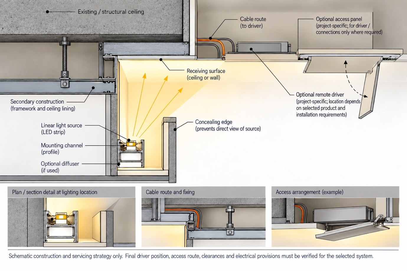
The service arrangement depends on the actual system. Some linear luminaires incorporate their driving equipment, while other arrangements require a separate driver or power supply. Electrical connectors, controls, and LED source lengths may also require future access. Therefore, establish their locations before closing the cove.
A separate driver is not automatically located immediately above the recess. Its position depends on the manufacturer’s permissible installation conditions, cable arrangement, ventilation requirements, electrical coordination, and available access. The design should not show a remote driver inside a permanently sealed void merely because that position appears convenient in section.
The KLUŚ POLI example demonstrates one useful aspect of service coordination. Its manufacturer describes a mounting arrangement that lets the lighting component be installed and removed using dedicated accessories. That is relevant to future access to the luminaire itself. It does not establish that every associated driver, connection, or control device can also be reached through the same opening. The service strategy must be assessed for the complete assembly.
In some installations, an accessible opening within the cove may be sufficient for servicing particular components. Other systems may require a separate access panel or another deliberate maintenance route. Where a removable panel is proposed, consider its position in relation to the finished architecture, but base its dimensions and fixing method on the actual equipment and servicing requirements.
A component's accessibility is not determined simply by whether someone can see it from below. A technician may need room to disconnect, remove, test or replace equipment safely. The access route must therefore allow the procedures required by the selected system. An opening that permits a photograph of a hidden driver may still be inadequate for servicing it.
Maintenance requirements also affect how the cove should be documented. The completion information should identify the selected luminaire and components, relevant electrical arrangements, driver locations where applicable, and instructions for reaching replaceable parts. Without this information, the next maintenance team may have to investigate concealed construction before it can identify the equipment.
This leads to a broader architectural principle: the quality of a concealed detail is not measured only by what disappears from view. It also depends on whether the hidden equipment can continue to function and be maintained without unnecessary disturbance to the completed building.
What the First Working Test Should Reveal
The first meaningful inspection of a concealed cove occurs when the intended lighting assembly operates within a sufficiently representative section of the actual construction. Until that stage, the drawings and product data describe expected behaviour. A working sample lets the team observe how the source, edge, and receiving surface interact under real conditions.
The sample does not always have to extend around the entire room. It should, however, include enough of the intended assembly to demonstrate the important relationships. Where a straight run is the main concern, a representative length may allow you to examine source concealment, mounting, illuminated surface, and visual continuity. Where corners or transitions are critical, the sample needs to include those elements as well. A short isolated strip cannot reveal every problem that may occur along a longer installation.
The first check concerns source visibility. From key occupied positions, can the viewer see individual emitters, the optical face, connectors, or exposed portions of the profile? If a source becomes visible, the team must determine whether the problem comes from the luminaire position, the fascia geometry, an unfinished edge, or the viewpoint itself.
The second check concerns the intended light distribution. Does the receiving surface display the general illuminated region established in the design? Are there concentrated patches near the recess, unexpectedly dark intervals, or sharp terminations? Relate these observations to source orientation, setback, optical characteristics, and surface condition rather than automatically attributing them to inadequate light output.
The third check concerns continuity along the run. Adjacent sections should be assessed for visible gaps, colour differences, changes in brightness, or interruptions caused by the arrangement of fittings and connectors. Corners and ends of runs need particular attention because their geometry differs from the continuous middle portion. Philips Color Kinetics specifically recognises end-of-run effects and changes in mixing behaviour in its cove guidance.
The fourth check concerns the receiving surface. Does the operating light reveal unexpected waviness, unfinished joints, paint inconsistencies or other defects? If so, the design team must determine whether the construction needs correction or whether the selected lighting arrangement is emphasising a surface characteristic that was not anticipated.
The fifth check concerns controls and electrical operation. Check the intended switching and dimming arrangements against the selected compatible components. If more than one run is controlled together, evaluate the installed result for consistency under the relevant operating states. A luminaire that switches on successfully does not necessarily mean the entire intended lighting system performs correctly.
Finally, test the maintenance arrangement rather than merely show it on paper. Where the system is designed for removal or access through a particular opening, the team should confirm that the intended servicing process remains feasible once the surrounding construction is complete.
Record these observations with dated photographs, annotated drawings, and clear notes distinguishing what was actually seen from what remains unverified. Camera exposure can make an illuminated band appear more continuous or dramatic than it does in person, so interpret photographic evidence with care. Where quantitative performance is required, appropriate measurements and photometric evaluation must supplement visual inspection.
For an important architectural cove, the sample can function as an approval point before the remaining installation proceeds. That is more useful than discovering the same problem only after all ceiling finishes are complete.
The Finished Effect Begins Inside the Detail
By the time a concealed cove is complete, much of the work that produced its final appearance has disappeared behind the architectural finish. The occupant may see a continuous illuminated ceiling or wall, but not the mounting profile, electrical connections, supporting framework, or precise source position. The visible effect appears simple because the construction has separated the illuminated surface from the equipment responsible for it.
This simplicity is not evidence that the detail required little design. A successful installation results from several coordinated decisions: the section establishes the physical relationship between source and surface; the recess provides an appropriate mounting space; the concealing edge controls direct visibility; the optical system distributes light towards the intended plane; the finish determines how that light is returned to the room; and the electrical and maintenance arrangements allow the installation to function after construction is complete.
The most instructive lesson from the three source-position studies is that concealment and distribution are related but competing requirements. Moving a source away from view may help conceal it while obstructing its useful output. Moving it closer to the opening may increase the illuminated area while making the emitter visible. The purpose of the detail is not to maximise either characteristic independently, but to establish a relationship that works for the selected product and project conditions.
The manufacturer example reinforces this conclusion. A real extrusion provides measurable dimensions, compatible mounting methods and defined component options. It allows the architect to coordinate an actual assembly rather than rely on a generic LED symbol. However, even the most detailed manufacturer specification does not determine the finished result without reference to the architectural recess, receiving surface and viewing conditions. Bring product data and construction drawings together.
A concealed cove can be drawn convincingly but built poorly. Drawings can establish intention, coordinate services and identify critical dimensions. They can reveal potential conflicts before construction begins. Yet the final effect depends on fabrication and installation accuracy, and you should check those conditions through a representative working sample and subsequent site inspection.
For homeowners, the practical question is whether the promised appearance is supported by a suitable product, a buildable detail and an understandable maintenance strategy. Two quotations describing concealed LED cove lighting may not include equivalent components or construction provisions. Asking how the source will be concealed, what surface will receive the light, and how the system can later be serviced is more useful than selecting solely from a photograph.
For professionals, the detail represents a coordination responsibility that extends from the architectural section to product selection, electrical integration, finishing, and inspection. The approved drawing must establish relationships that the contractor can execute and the completed installation can be assessed against. When product-specific instructions add requirements, incorporate them before construction proceeds.
For students, the detail offers a valuable technical exercise. One carefully drawn section can be developed into several alternatives, each changing a single variable: source position, fascia height, receiving surface, or observer location. Comparing those alternatives demonstrates how architectural geometry influences what becomes visible. It also establishes the limits of a drawing and why manufacturer documentation and physical observation remain necessary.
A concealed cove light is therefore an example of architecture making its own construction disappear without making that construction irrelevant. The finished room may reveal only a continuous band of reflected light, yet the result depends on the accuracy of components, surfaces and connections that the viewer cannot see. The detail succeeds not simply because the source is hidden, but because the building has been designed and constructed to conceal the equipment while preserving the light it is meant to deliver.
SOURCES & TECHNICAL REFERENCES
1. KLUŚ — POLI Extrusion (A07176) / Official Product Information and Technical Specifications
Manufacturer documentation covering the aluminium profile’s dimensions, intended cove applications, adjustable orientation, compatible components and assembly method.
2. KLUŚ — POLI Mounting Bracket (C24112C10) / Official Mounting Bracket Specifications and Instructions
Reference for the mounting arrangement, angular adjustment and installation/removal of the lighting component using dedicated accessories.
3. Philips Color Kinetics — LED Cove Lighting: Design and System Guide / Technical Guide (PDF)
Technical background for source position, setback, standoff, aiming, light mixing, uniformity and the relationship between the luminaire and receiving surface.
4. Philips Color Kinetics — Concealed Interior Product Guide / Manufacturer Technical Guide (PDF)
Reference for concealed lighting technologies, product selection, optical characteristics and integrated architectural lighting systems.
5. Philips Color Kinetics — eW Cove QLX Powercore / Product and Installation Guide (PDF)
A separate manufacturer example supporting discussion of electrical coordination, luminaire connections, installed lighting runs and installation planning.