
The Indian Lantern, Re-read
The Geometry of an Opening
PAGE 1 — A Pattern Is Not Yet a Shadow
A perforated lantern can appear to perform a simple transformation. A craftsperson cuts a decorative pattern into metal, places a light source inside the enclosure, and the pattern appears again on the surrounding wall. In photographs, the relationship can seem almost exact: a flower-shaped opening becomes a larger flower-shaped patch of light, repeated across the room. The impression is that the lantern transfers its ornament from one surface to another, changing only its scale. Yet the physical process is more complicated. The opening is not an image that light carries away intact. It is a boundary through which certain light paths pass and others do not. What appears on the receiving surface depends on the arrangement of the source, the opening, and the surface, not on the decorative design alone.
This distinction changes how we understand the lantern as a crafted object. The perforations are made before introducing the light source. Manufacturing decisions set their edges, spacing, and relationship to the remaining metal. But the visible pattern produced by illumination is not determined only by those decisions. Two lanterns with identical metal enclosures could produce different projected appearances if the sources inside differed in size, position, or distribution. Similarly, one unchanged lantern could produce different results when placed at different distances from a wall or fitted with another suitable source. The manufactured object remains the same, while the illumination geometry changes.
We can observe a related principle in an everyday shadow. A small, compact light source can create a shadow with distinct boundaries, provided the arrangement allows the source to behave like a point. A larger source creates overlapping regions of illumination and obstruction, softening the boundaries. The shape of the object casting the shadow has not changed. The source geometry has changed. A perforated lantern introduces this principle within a more complicated enclosure, because instead of one obstruction there may be hundreds of small openings across several differently oriented faces.
There is another reason to examine the lantern more carefully. The pierced pattern must remain physically viable before it can influence light. Every opening removes material. The remaining portions must retain the intended form, survive the operations to make them, and connect to other parts of the enclosure. A pattern that looks convincing as a drawing may become difficult to execute when transferred to a sheet that must later be folded, shaped, or joined. The craftsperson is therefore not simply cutting decoration into metal. The work involves negotiating what can be removed, what must remain, and how the resulting surface will become a three-dimensional object.
The relationship between making and illumination is interesting because the two processes operate at different scales. A slight irregularity at the edge of a perforation may be easy to identify when the metal is examined closely but much less apparent in a soft projected pattern. Conversely, a small change in source position may substantially alter how several faces of the lantern contribute light to the room. Craft precision matters, but the optical result cannot be read directly from workmanship alone.
This article investigates that relationship through one documented example: a perforated hexagonal hanging lampshade described in the Census of India's historical study Brass and Copper Art Wares of Delhi. The study is valuable because it records operations involved in making a particular object, including forming, chasing, perforation, assembly, and finishing. It provides a factual starting point for examining what the maker constructed. The subsequent study of projected light must be treated separately, because a historical manufacturing record is not automatically a record of the lantern's performance under a particular lamp.
Our investigation therefore follows two connected questions. First, how does a craftsperson turn an arrangement of openings into a stable enclosure? Second, what happens to that arrangement when light travels through the completed object and reaches another surface? The first can be examined through documented making processes and the physical logic of metalwork. The second requires an understanding of optical geometry and, where possible, a controlled physical test.
The lantern is a small object, but these questions extend well beyond decorative lighting. They concern the difference between a designed opening and the effects that opening can produce. That difference matters for pierced screens, patterned architectural enclosures, light-filtering partitions, and other situations in which a solid boundary is deliberately interrupted. The lantern offers an opportunity to study it closely, without assuming that its scale or historical construction can be transferred directly to a building.
PAGE 2 — The Delhi Object: What the Record Actually Tells Us
A serious examination of a craft tradition becomes more useful when it begins with an identifiable object rather than a broad account of regional style. The phrase Indian lantern covers objects made from different materials, manufactured by different techniques and used in different settings. It cannot provide a single account of construction. A pierced brass hanging lampshade, a paper lantern and a fabricated contemporary metal pendant may all produce decorative light, but their relationship between material, structure and illumination is not the same.
The Delhi example provides a more defensible starting point. The Census of India's 1961-era handicraft documentation, published as Brass and Copper Art Wares of Delhi, describes a perforated hexagonal hanging lampshade and records successive manufacturing operations. The historical account places the object within a documented field of brass and copper metalworking rather than treating it as an anonymous ornament. Its significance for this article is the specificity of the production process: separate metal components are prepared and shaped, decorative work is undertaken through chasing and perforation, and the parts are fitted together to form the hanging object.

The description establishes that the lampshade belongs to a metalworking practice in which ornament is produced through physical operations on a sheet. This differs from applying a printed pattern to an already complete enclosure. The openings affect the material's continuity; the chased marks modify its surface; and the joining process turns worked components into an assembled body. Each operation contributes a different condition that we can examine in the finished object.
However, the documentary record also has limits. It does not automatically tell us the exact alloy composition of every surviving example, the dimensions of a particular lantern in an unrelated photograph, or the identity of an artisan whose work has not been individually attributed. Nor should we assume the documented historical production sequence describes every lantern produced in Delhi today. The source records a practice in a particular historical context. Contemporary workshops may use different tools, manufacturing sequences, joining techniques, and finishing methods.
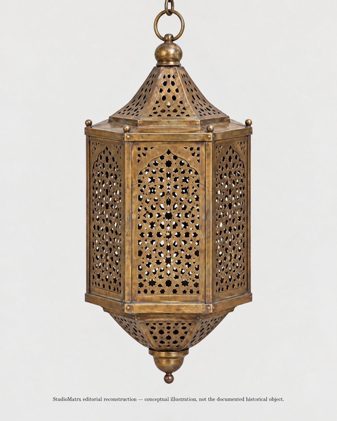
The same caution applies to images. A photograph of a modern hexagonal lantern may illustrate a comparable form, but visual similarity does not establish that it is the historical lampshade described in the Census study. Reconstructing a perforation pattern for explanatory purposes is likewise different from reproducing the original artisan's drawing. Where an illustration is based on general principles rather than surviving measured documentation, the reader should be told precisely what it represents.
What, then, can we learn from the historical account with confidence? We can examine the relationship among formed sheet components, perforated ornament, and assembly. We can study why decorative operations need to be sequenced around access to the material and why separate faces and caps must be coordinated before the enclosure is complete. We can consider the physical consequences of removing material and the role of joints in preserving the form. These questions arise directly from the described making process without requiring us to invent undocumented workshop decisions.
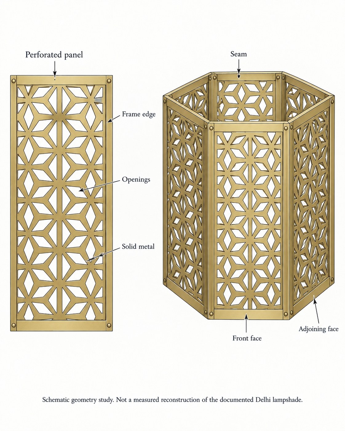
The hexagonal geometry is especially useful. Unlike one flat perforated sheet, a lantern with six sides contains multiple surfaces oriented in different directions. The maker must bring these surfaces together at the enclosure's edges. A decorative design developed on one face encounters a seam when it meets another. The construction itself therefore changes how the pattern is perceived. From one viewpoint, the observer may see a single face almost frontally; from another, several faces appear together, with their openings partly overlapping in perspective.
The object also contains upper and lower portions that complete the enclosure. These components are not merely decorative endings. Their form affects the overall assembly, the relationship between the faces and the potential directions through which light might pass. Without a measured drawing of the actual historical object, we should not claim exact angles, proportions, or optical behaviour for those elements. Nevertheless, their presence makes the construction problem richer than that of a perforated flat panel.
For this article, the historical record will serve as evidence of making. Later optical drawings will serve as analytical studies. Keeping these two forms of evidence separate lets us investigate the object seriously without turning a conceptual illustration into an invented archival fact.
PAGE 3 — The Strength of What Remains
When we look at a perforated metal panel, the openings tend to attract our attention first. They form the recognisable ornament: a sequence of circles, geometric stars, floral figures or interlocking shapes. The remaining metal may seem to be nothing more than the background that separates these openings. For the craftsperson, however, the remaining material is as important as the material removed. It is the continuous network through which the panel maintains its shape, connects to neighbouring components and resists damage during making and handling.
This creates a fundamental design problem. The ornamental drawing shows where openings should occur, but it does not establish whether the remaining metal can perform its physical role. If openings are too close together, narrow connections may remain between them. These connections can become vulnerable to distortion during chasing, piercing, bending, handling, or assembly. If a perforation approaches a joining edge, it may leave insufficient uninterrupted material for the connection. The appropriate limits depend on the metal's composition, thickness, condition, geometry, and manufacturing method; no universal minimum strip width derived from the appearance of a historical lantern.
The problem becomes clearer when we imagine a flat metal sheet divided into two regions. One contains small openings separated by broad continuous areas of metal. The other contains larger openings joined by a delicate network of narrow strips. Even if the total sheet dimensions are identical, the two patterns create different physical conditions. Their response to forming and handling cannot be assumed equivalent. The arrangement of openings changes the material's remaining load paths, local flexibility, and susceptibility to deformation.
The direction of those remaining connections also matters. A narrow strip between two openings may align with the principal direction of bending or loading, or it may cross that direction. Corners and small internal radii can concentrate stress in ways that broad uninterrupted regions do not. These effects matter when a pattern must undergo further forming after perforation. A design readily produced on a flat piece may require a different sequence of operations if the same material must become part of a three-dimensional lantern.
Historical handwork introduces another consideration: the force used to create the opening. Piercing is not simply the disappearance of metal from a predetermined shape. The tools exert force on material that requires support. If the sheet is inadequately supported or the working sequence is poorly controlled, local distortion may occur. The arrangement of openings can affect not only the finished object but also how difficult it is to produce.
This helps explain why a maker's knowledge cannot be reduced to copying a motif. A craftsperson must consider how the sheet will be held, where tools can reach, whether earlier operations weaken areas needed for later work, and how the panel will be joined to its neighbours. The decorative arrangement must survive a series of transformations. Some patterns may be visually elaborate but straightforward to produce under one set of conditions; others may appear simple yet become difficult because of their location near a fold or connection.
This distinction matters especially for contemporary designers working with digital pattern files. A computer can generate fine repetitions and intricate cutouts without understanding the intended material or fabrication sequence. The file may be geometrically correct yet unsuitable for the proposed thickness, forming method, or supporting frame. Manufacturing feasibility is not guaranteed by the precision of a digital outline.
For homeowners considering a handcrafted pierced-metal lantern, this offers a different way to assess quality. Instead of looking only at how elaborate the pattern appears, they can inspect whether the openings are cleanly formed, whether the surrounding strips show obvious distortion, whether the faces are properly supported, and whether the frame and seams are convincingly resolved. The objective is not to impose machine-like regularity on handmade work but to distinguish intentional craft characteristics from damage or poor construction.
For architectural professionals, the lesson extends to patterned panels and screens. Removing material changes the physical behaviour of the element, and the supporting arrangement must be designed accordingly. A lantern illustrates this at a manageable scale but does not establish structural rules for full-size building screens. Those require their own engineering assessment, material specifications, and connection design.
The more closely we examine the pattern, the less useful it is to describe the metal simply as the space between the holes. In a pierced object, the remaining material is the construction. The openings exist only because that construction has been deliberately preserved.
PAGE 4 — When a Flat Pattern Meets a Corner
A perforation drawing is usually easiest to understand when viewed flat. Individual openings can be located, repeated, mirrored and arranged within a defined boundary. The drawing allows the designer to examine spacing and relationships without the complication of perspective. But a hexagonal hanging lantern is not experienced as six independent drawings. Its faces meet at corners, and the assembled enclosure transforms their individual patterns into one spatial arrangement.
Imagine a repeated motif placed at the centre of each face. On a flat drawing, the repetition may appear perfectly consistent. Once the faces are brought together, the viewer rarely sees all six equally. The nearest face may appear broad and almost frontal, while adjoining faces are foreshortened. Their openings appear compressed by perspective. As the viewer moves around the object, those relationships change. The motif has not physically altered, but the geometry through which it is seen has.
This is not necessarily an imperfection. It results from giving the pattern a three-dimensional body. The repetition across faces establishes an order, while the changing viewpoint makes that order perceptually variable. A lantern can therefore be visually more complex than any one panel, even without illumination.
Corners are particularly significant because they interrupt the surface's continuity. A motif approaching an edge may terminate before the seam, continue visually around the corner or be deliberately reorganised within a framed border. Each approach produces a different relationship between ornament and construction. A strong frame may emphasise the separation of the six faces, making the lantern appear as an assembly of panels. A more continuous pattern may encourage the viewer to read the enclosure as one decorative surface, even though joints remain necessary.
The historical Delhi account records the formation and assembly of separate components, but without an accurately reproduced pattern drawing we should not assign one particular edge-treatment strategy to its documented lampshade. We can, however, study the choices such a construction makes possible. These are useful analytical categories, not claims about undocumented details of the original object.
An important distinction exists between continuity in the drawing and continuity in the final assembly. A motif might align perfectly on paper but become interrupted by the thickness of a frame or the overlap needed for joining. The maker may need to allow for these features before the decorative work begins. If the edges must be folded or joined, the material occupied by that operation cannot be treated as a completely unobstructed decorative face.
The problem is comparable to the difference between a building elevation and a building corner. An elevation can show a repeated series of openings along one surface. Yet how the wall turns, meets another material, or approaches an entrance may determine whether the composition reads as continuous or interrupted. The lantern is not a substitute for architectural analysis, but its small enclosure makes this relationship unusually easy to isolate.
The interior view of a perforated lantern adds another complication. Through one opening, the viewer may see another face of the enclosure. The visible background is no longer necessarily the room beyond; it may be a second perforated metal surface at another angle. Its openings can overlap visually with those of the nearer face. As the observer moves, the apparent alignment changes. This layered view is a geometric effect of the enclosure, independent of illumination.
That observation becomes important later when we consider projected light. The visible pattern on the object itself, the apparent overlap of openings viewed through the enclosure and the pattern projected onto a wall are three different visual conditions. They should not be treated as interchangeable representations of the same ornament.
A carefully executed drawing for this investigation would show one flat illustrative panel and the same panel within a six-sided enclosure. It would identify the panel boundaries, seams and viewing directions without inventing historical dimensions. The point would not be to reconstruct a lost workshop drawing. It would show how an arrangement designed on a plane acquires new relationships when assembled in space.
PAGE 5 — Why the Order of Making Matters
A finished lantern conceals much of the sequence of its production. The viewer sees a unified enclosure, not the separate moments when the sheet was cut, worked, pierced and joined. The historical Delhi account is especially valuable because it allows us to recover those different operations and understand why they cannot be treated as interchangeable.
The manufacturing sequence matters because every operation changes the conditions under which the next one must be performed. Cutting establishes the components' outline. Forming changes their geometry and may influence where a tool can reach. Chasing produces surface marks and decorative relief. Perforation removes material. Assembly brings worked parts into a final spatial relationship. Finishing completes the visible surfaces and connections. The sequence described in the historical record should be understood in its documented context, not converted into a universal recipe for contemporary production.
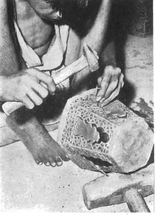
Consider the problem of tool access. A separate metal panel can be positioned on a working support in ways that a completely enclosed lantern may not allow. The artisan may need to resist the force of a chisel or piercing tool from beneath the sheet. Once several faces and caps have been assembled, access to the interior becomes restricted. An operation that was manageable on a separate component may become difficult or impossible without changing the tools or construction strategy.
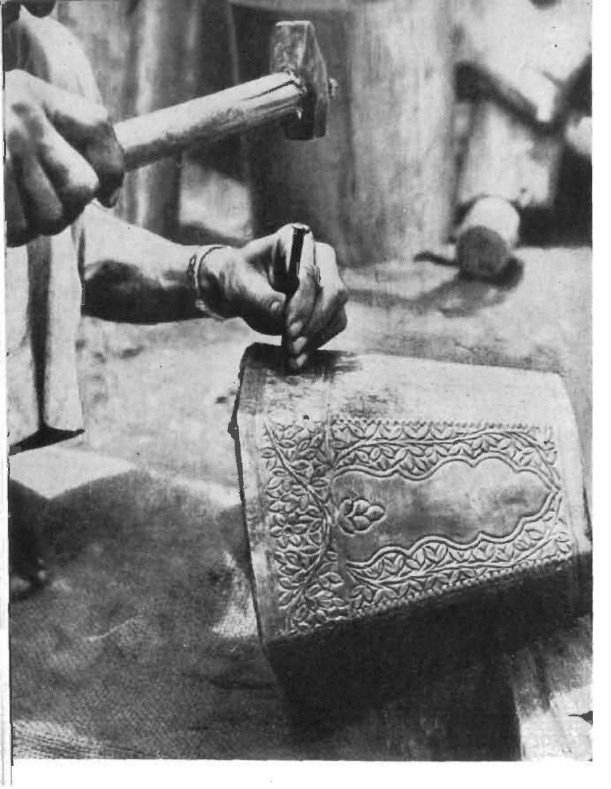
The support beneath the metal is as important as the tool applied above it. The surface needs to be held securely enough to receive the intended marks without unwanted movement or deformation. Historical craft records describe different support materials and implements used for worked-metal decoration. Those descriptions demonstrate a relationship between tool, material, and temporary working arrangement. They do not provide a modern safety specification, nor do they justify replicating the process without suitable training.
Chasing is particularly interesting because it produces a visual result without necessarily removing material completely. A worked line or depression can modify how a surface catches light. Perforation, by contrast, establishes an opening through which light may travel. A lantern combining these operations can therefore contain two kinds of ornament: features remaining within the solid metal and actual interruptions in the sheet. The two may be composed as one pattern, but their physical effects differ.
This distinction has editorial importance. A photograph of a craftsperson striking a chisel cannot automatically be captioned perforation. The tool may be marking, chasing, cutting, or performing another operation. Without knowing what is actually taking place, we risk replacing craft knowledge with a generic image of manual labour. A technically informative caption should identify the operation only when the source supports that identification.
The documented process also complicates the idea that historical handcraft was simply less precise than contemporary machine work. A different tool does not imply an absence of planning. Repeated manual operations require control over spacing, alignment, support and the relationship between individual components. The standards of accuracy may be expressed differently from those of digitally controlled manufacturing, but the work still depends on decisions about how to produce a pattern consistently enough for its intended form.
At the same time, romanticising irregularity would be equally misleading. Not every variation in a handmade component is intentional. Distortion, damaged edges and badly aligned joints can be faults. The maker's skill lies partly in understanding which variation belongs to the process and which compromises the object.
For contemporary designers, the most useful lesson is not that every lantern should be handmade. It is that fabrication sequence belongs inside the design process. A digitally cut metal screen may require bending, fastening, surface finishing, or connection to another system after cutting. If those operations are not considered before the pattern is finalised, the digital accuracy of the perforations may do little to prevent problems during assembly.
The historical lantern makes this dependency visible. The pattern is not completed when it is drawn, and the object is not completed when the pattern is pierced. The components must pass through a coordinated sequence in which design becomes physical work.
PAGE 6 — The Seam Is Part of the Ornament
When you examine a perforated panel on its own, its pattern may seem like the main design achievement. Once several panels are assembled, the joints between them become equally important. They establish the enclosure's geometry, maintain relationships among adjoining faces, and determine how the object behaves when handled or suspended.
For the documented hexagonal hanging lampshade, the historical account describes fitting together the body and associated parts, including the caps, with joining operations used where required. The assembled form therefore results from more than the perforation work. Separate components must be brought into a consistent relationship, and their connections must preserve the intended shape.
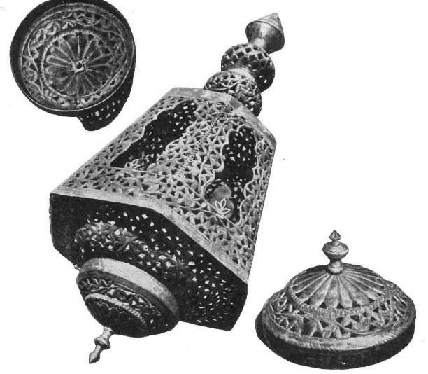
A frame surrounding a perforated face can perform several functions. It can provide a comparatively uninterrupted region for joining, organise the boundary of the ornament and make the faces visually distinct. Depending on the actual construction, it may also contribute stiffness or support. However, a visible frame in an illustration does not establish its exact structural performance. That can only be assessed for the particular material, dimensions, and connection arrangement.
The relationship between frame and perforation raises an interesting question: where does the ornament end? If the perforated motif is deliberately contained within a solid border, the border becomes part of the visual composition. It defines the pattern's limit and establishes a rhythm between open and closed material. If the panel meets another face at a seam, that seam becomes part of the enclosure's repeated geometry.
The same principle applies to the lantern's upper and lower portions. The caps change the silhouette and can conceal or reveal parts of the internal arrangement. They may also interrupt the path light takes as it leaves the enclosure. A decorative cap with perforations behaves differently from an opaque cap, but you can't infer the exact effect without knowing the dimensions, the internal source, and the surrounding geometry.
The hanging connection deserves particular attention. Because the object is suspended, its weight must be carried through a physical connection to a suitable support. The decorative ring visible at the top is not necessarily enough information to determine whether an installation is safe. The load path, connection integrity, and suitability of the supporting building element require assessment for the actual lantern and its intended use. A historical photograph or an AI-generated reconstruction cannot establish those requirements.
This is where the difference between a crafted object and a decorative image becomes particularly clear. An image can show an elegant perforated enclosure without showing whether the individual faces are properly attached, whether the caps can withstand handling, or whether the suspension arrangement is dependable. The appearance of completeness is not proof of technical completeness.
A physical inspection should therefore include views that decorative photography often omits: the back of a joint, the inside edge of a perforated panel, the connection between the body and cap, and the place where the hanging component meets the enclosure. These areas may reveal more about how an object was made than its most elaborate front-facing motif.
For professionals working with contemporary craft-based objects, this suggests a straightforward requirement. Product documentation should distinguish the ornamental panel from its supporting structure and should identify which components are essential to the object's integrity. A visually faithful reproduction can use a different construction method, but it should not disguise that difference with claims that imply historical authenticity.
For students, the lantern provides a valuable drawing exercise. A front elevation may communicate the ornamental composition, but a section through a corner and an exploded assembly drawing explain something different: how the components actually meet. Together, the drawings move the study beyond appearance and into construction.
The seam is not an interruption to the real design. In a three-dimensional perforated object, it is one of the decisions that makes the design possible.
PAGE 7 — An Opening Does Not Carry an Image
The moment a light source enters a perforated enclosure, the lantern begins to operate according to relationships different from those governing its manufacture. The metal has been shaped and pierced. Its openings already exist. But the light reaching a surrounding surface is not a physical copy of the ornament removed from the sheet. It is the result of rays travelling from a source through available openings and reaching a receiving plane.
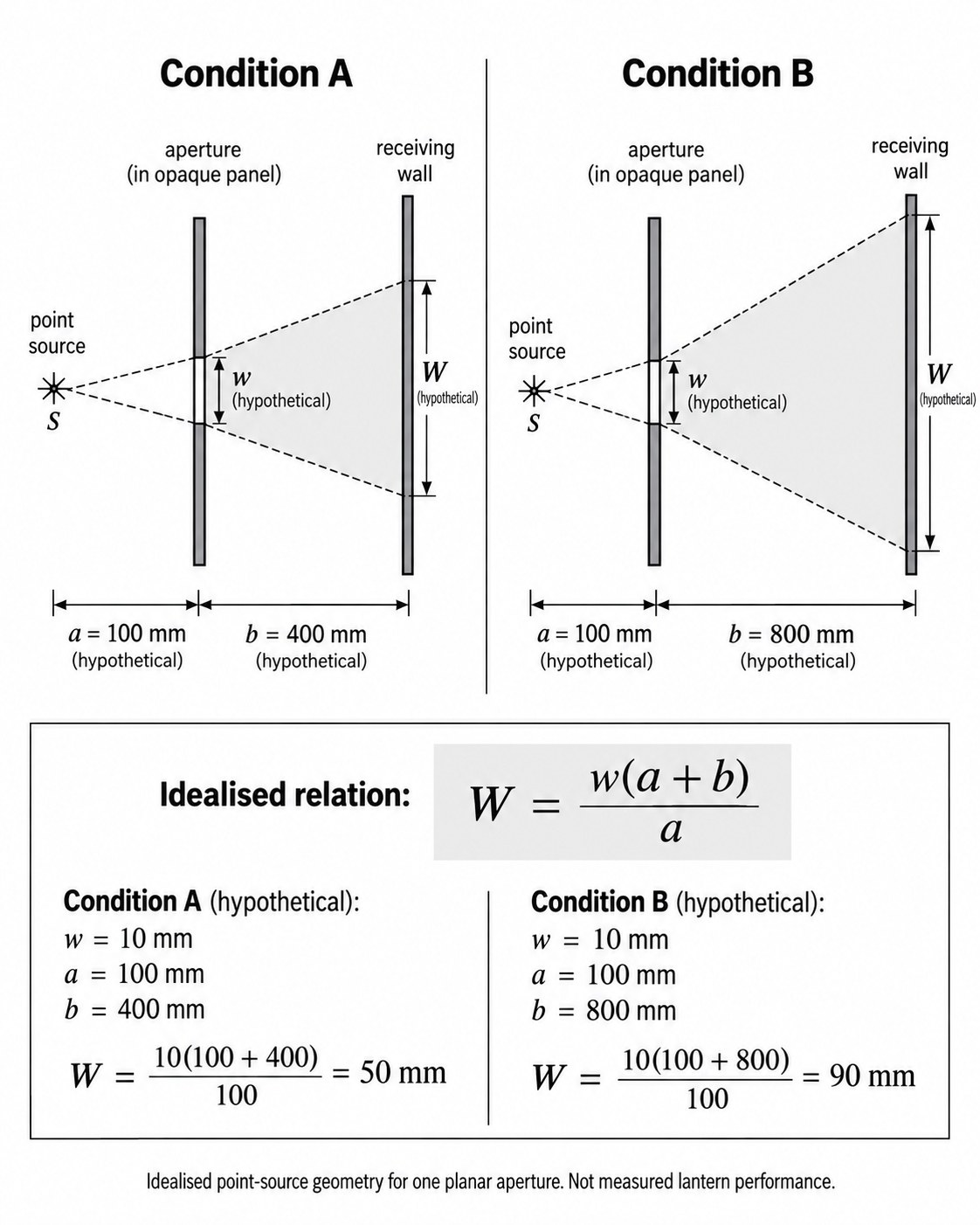
To understand this, consider the simplest possible arrangement before introducing the complete lantern: one small source, one flat opaque panel containing an opening, and one wall behind it. A ray travelling from the source either encounters the opaque material or passes through the opening. The light reaching the wall is bounded by the paths that can pass through the opening. You can construct these boundaries geometrically by drawing rays from the source through the aperture edges to the receiving surface.
The resulting illuminated region depends on the separation between these elements. Move the receiving wall farther from the opening while leaving the source fixed, and the illuminated region generally increases in size in this simple arrangement. Move the source closer to the opening, and the divergence of the rays passing through it becomes more significant. The aperture has not changed, but its projected result has.
The geometry can be expressed through a simple similar-triangle relationship. For a point source and an aperture in parallel planes, with the source and aperture aligned normal to the planes, the projected linear dimension is proportional to the ratio between the source-to-receiving-surface distance and the source-to-aperture distance. If the source-to-aperture distance is a, the aperture-to-wall distance is b, and a characteristic opening width is w, the projected width W in this idealised arrangement is:
W= w (a+b)/a
This is a geometrical model, not a measurement of the historical lantern. It assumes a point-like source, simple planar geometry, and no additional obstruction. The equation becomes less directly applicable when the opening is tilted, the receiving wall is oblique, the source is extended, or the enclosure contains other surfaces that interrupt the light.
A fictional example makes the relationship easier to understand without inventing historical dimensions. Suppose an opening is 10 mm wide and the point source is 100 mm behind its plane. If the receiving wall is 400 mm beyond the opening, the idealised projected width is 50 mm. Place the wall 800 mm beyond the same opening, and the projected width becomes 90 mm. In both cases, the opening is still 10 mm wide. The change occurs because of the distances involved.
These calculated results should not be mistaken for the expected performance of a complete decorative lantern. The example deliberately isolates one aperture and one source so you can understand the basic geometry. A real lantern may have an LED module, diffuser, reflector, or several emitting regions. The perforation may lie on an angled face rather than a plane parallel to the wall. Other parts of the lantern may interrupt the rays. The receiving wall may also be inclined relative to the aperture.
This is why a lantern's perforated pattern should not be described as a stencil that always transfers its image unchanged. A stencil held very close to a surface can produce a result quite different from a perforated enclosure placed farther from the wall with an internal light source. The relationship between aperture and illuminated image must be constructed or observed for the relevant geometry.
For architectural readers, the larger lesson is that a designed opening does not independently determine its associated light pattern. The spatial arrangement completes the optical system. That holds whether the opening belongs to a small metal lantern or a larger light-filtering element, though real architectural conditions introduce further variables that require separate study.
PAGE 8 — Why the Shadow Loses Its Edge
A perforated lantern may produce sharply recognisable motifs in one lighting arrangement and a soft, overlapping pattern in another. The temptation is to explain this difference through the ornament's complexity: perhaps the perforations are too small, too closely spaced, or insufficiently precise. Those factors may matter, but one of the most important variables is the light source itself.
A point source is a useful idealisation because light reaches each aperture from one defined position. The projected boundary can therefore be studied through relatively simple ray geometry. Real light sources, however, have physical dimensions. An LED package, a small lamp or an illuminated diffuser may contain an emitting area rather than a single point. Different points across that area send light through the same opening along different paths.
As a result, one aperture can produce multiple slightly displaced contributions to the receiving surface. Where these contributions overlap, the illuminated area may remain bright. Near the boundaries, only part of the emitting source may be visible through the opening from a given position on the wall. The transition from light to dark can become gradual rather than sharply defined.
The gradual transition between illuminated and darker regions can be understood through geometrical principles related to the penumbra. In a conventional shadow, the penumbra forms where a light source is only partially obstructed. In a perforated lantern, a related effect occurs at the boundaries of transmitted light, where different portions of an extended source become visible through the opening. The resulting softness depends on the source’s emitting area, its position, the aperture geometry and the distance to the receiving surface.
The source's apparent size from the opening is especially important. A physically small source placed close to the aperture may subtend a substantial angle, while a larger source positioned farther away may subtend a different angle. Simply calling one lamp small and another large does not fully describe the resulting softness. You must consider their dimensions and positions together.
The aperture-to-wall distance also matters. As light travels farther beyond the opening, contributions from different source positions can separate more widely on the receiving surface. Under some arrangements, the pattern becomes increasingly diffuse as the wall moves away. An enlarged decorative projection may gain scale while losing the edge definition that made the original metal motif recognisable.
This creates a useful distinction between light transmission and pattern recognition. A perforated lantern may transmit considerable light while producing little recognisable ornament on a distant surface. The room can receive illumination even when the individual projected motifs overlap so extensively that they no longer appear as separate shapes. Conversely, a sharply defined projection may occupy selected regions while leaving other parts of the surrounding space comparatively dark.
A diffuser introduces another variable. In some contemporary lanterns, it may reduce the direct visibility of individual emitters and produce a more continuous illuminated appearance. But inserting a diffuser changes the apparent source geometry presented to the perforations. The result may be more uniform illumination of the enclosure while the projected pattern becomes less distinct. This is not necessarily a failure. It may be exactly what the designer intends. The important point is that improving one visual characteristic can change another.
For this reason, a catalogue photograph showing a lantern glowing evenly does not establish that it will project sharp shadows. Equally, a dramatic photograph of patterns on a wall does not prove that the lantern provides comfortable general illumination. These are separate performance characteristics, each needing its own evidence.
The distinction also exposes a limitation in AI-generated imagery. An image generator may produce a beautiful lantern with exceptionally sharp and intricate wall patterns, but it does not establish that a physically possible source and aperture arrangement would produce those exact projections. Such an image can illustrate decorative light but cannot be treated as a controlled demonstration of optical performance.
For our investigation, the appropriate visual is a schematic comparison that fixes the aperture and receiving surface while changing only the source from relatively compact to extended. The drawing can show the different limiting rays and the resulting edge transitions. It must not imply measured shadow sharpness or present its simplified optical construction as a photograph of the historical lantern.
The reader discovers that the delicacy of a projected pattern is not proof of the metalwork's delicacy alone. The light source helps draw that pattern on the wall.
PAGE 9 — Six Faces, Six Directions
The flat-aperture model explains how source size and distance influence the appearance of a projection, but the hexagonal lantern introduces another difficulty. Its openings don't lie on a single plane. They are distributed across faces that meet at different angles, so the directions available to light change around the enclosure.
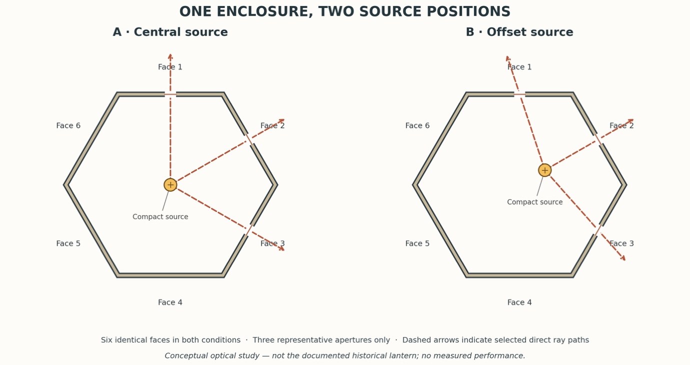
Imagine a compact source positioned within an illustrative six-sided lantern. On a face directed towards a nearby wall, light passing through its openings may reach that wall in a relatively direct relationship. An adjacent face is angled differently. Its openings permit light to leave in another range of directions, so its projected contribution may travel toward a different part of the room or intersect the first contribution obliquely.
This has consequences for both pattern scale and shape. An aperture viewed or projected obliquely does not necessarily produce the same shape as one aligned with the receiving plane. Depending on the arrangement, the projected region may stretch, skew, or otherwise transform. Its apparent size can vary across the projection because different parts of the opening are at different distances or angles relative to the source and receiving surface.
The light source's position within the enclosure becomes especially important. If the source is approximately central, the relationships to the six faces may be more symmetrical in a geometrically regular model, although this does not guarantee equal illumination because real emitters may have directional output. If the source moves toward one face, the distance and angular relationship to that face change, while the relationships to the other faces change differently. The lantern's exterior geometry remains fixed, but its transmitted-light pattern can be redistributed.
A deeper distinction exists between a regular geometric model and an actual crafted object. A true regular hexagonal enclosure has equal face widths and consistent angular relationships in plan. The historical lampshade may be described as hexagonal without providing every dimension needed to reconstruct its precise geometry or internal lamp position. We should therefore use a deliberately declared schematic model for the optical study, not claim to reproduce the original object's unseen dimensions.
The upper and lower caps introduce further complications. They may contain perforations, solid regions and junctions that affect the available light paths. A source positioned near the centre of the body may illuminate the upper cap differently from the lower cap. Some emitted rays may be intercepted by framing elements or other internal components. The physical organisation that enabled the enclosure to be assembled also influences its optical possibilities.
This relationship suggests an important way of reading the lantern. The six faces do not simply repeat decoration around an object; they establish different directional channels through which light can emerge. A repeated motif may therefore produce a set of projections that are not identical in scale, sharpness or placement. The apparent inconsistency may arise from the enclosure's spatial geometry rather than differences in the panels' workmanship.
A contemporary designer might deliberately exploit this behaviour. An enclosure could be designed so selected faces direct light toward different receiving surfaces. Other faces could remain solid or contain smaller openings to reduce transmission in particular directions. However, the actual result would have to be verified with the proposed source and material. The historical Delhi account should not be used to attribute such contemporary lighting intentions to an artisan without documentary support.
A simple plan drawing can explain the principle more effectively than a dramatic rendering. Draw a six-sided body, place a hypothetical source at its centre and trace representative rays through openings on two differently oriented faces. Then move the source within the same outline and show how those paths change. The viewer can see that the projected effect depends on both face orientation and source location.
This exercise is distinct from the room-by-room lighting guidance elsewhere in the magazine. We are not deciding how many decorative lanterns a room requires or where to suspend them. We are examining what the enclosure makes optically possible.
The hexagonal form reveals what the flat pattern conceals: once a perforated surface becomes an enclosure, each opening's orientation becomes part of the optical design.
PAGE 10 — The Pattern on the Wall Is a Different Drawing
By the time light reaches a receiving surface outside the lantern, it has passed through a sequence of spatial relationships. It originates at a source, travels towards the perforated enclosure, passes through selected openings and continues until it encounters another surface. Each element contributes to the result, yet the final pattern usually attracts attention. The illuminated wall appears to display the lantern's ornament, as though the object has extended its decoration into the surrounding architecture.
A more accurate interpretation begins by recognising that the physical perforation and the projected pattern are different drawings. The first is established through material removal. Its boundaries are the metal's edges. The second is established through light propagation. Its boundaries are determined by the directions from which the source can be seen through those openings and by the geometry of the receiving surface.
The distinction explains why the projected pattern may contain forms that were not obvious when the perforated panel was examined directly. Two neighbouring openings may produce projected regions that overlap. Their combined illumination may appear as a larger connected figure rather than two separate motifs. Portions of a pattern may become indistinct because their light contributions merge. A corner or framing member may interrupt a projection, introducing a boundary that did not belong to the decorative motif itself.
The receiving surface can further change the projected design's appearance. On a flat wall, the geometry may be comparatively straightforward to analyse. On a wall that changes direction, the projection encounters different receiving planes. A pattern crossing a corner can change scale and apparent shape as it passes from one surface to another. If the receiving surface contains recesses, projections or openings of its own, the image may be interrupted or broken into separate regions.
A textured wall adds another level of visual complexity. The incoming light is distributed across a surface whose small-scale orientation changes from point to point. Local highlights and shadows may alter the visibility of the projected motif. A highly reflective surface may introduce visible reflections or redistribute the light differently from a matte finish. These factors affect appearance, but they do not establish that the aperture geometry itself has changed.
For a photographic investigation, document the relationship between the lantern and the receiving surface together. A close-up image of the illuminated lantern cannot tell the reader where its light is going. A photograph of patterns on a wall, without showing the source and enclosure, cannot establish which openings produced them. The strongest documentation includes both the object and the illuminated surface, with enough information to understand their physical arrangement.
The source should be identified. Its approximate emitting dimensions, optical arrangement, and position relative to the enclosure affect the result. Record the separation between the lantern and the receiving surface where possible, along with the orientation of the receiving plane. A controlled comparison should also consider camera position and exposure because photographs can alter the apparent brightness and clarity of light patterns.
These requirements matter most when comparing two different sources. If the goal is to understand how source size changes shadow definition, keep the enclosure and receiving surface fixed. If the goal is to understand how wall distance changes projection scale, keep the same source and aperture geometry. Changing several conditions simultaneously may produce an attractive set of images, but it weakens the reader's ability to identify the cause of the difference.
Such a test does not require a historic lantern. A carefully documented contemporary perforated object or purpose-made panel can be used to study the optical relationships. However, the publication must distinguish that experiment from the archival Delhi case. A result obtained using a modern metal panel should not be described as the historical lantern's demonstrated performance.
This separation between documentary history and contemporary analysis is not a weakness. It allows the reader to understand exactly what is known. The historical evidence explains how the object was made. The technical study explains the behaviour of light through representative openings. A physical mock-up, if available, shows what happened under the stated test conditions. Together, these forms of knowledge produce a more useful article than a photograph whose attractive effects are impossible to verify.
The projected image is therefore not simply decoration escaping the lantern. It is the visible consequence of the relationship among manufactured openings, a particular light source and the receiving architecture.
PAGE 11 — A Small Experiment That Can Reveal a Great Deal
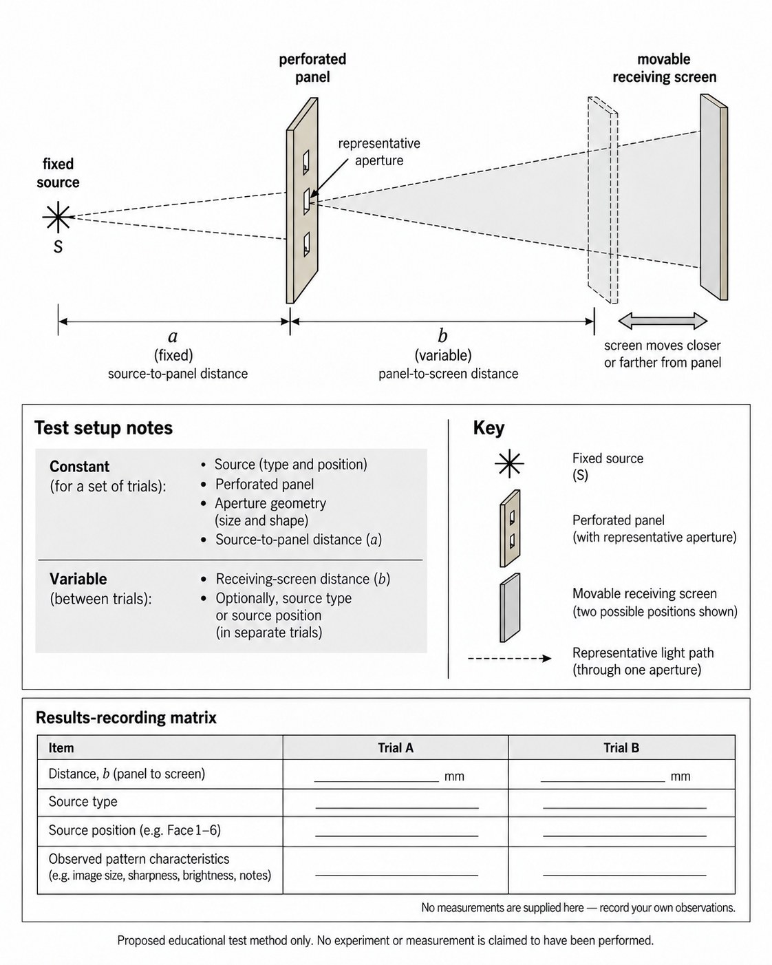
The relationship between opening geometry and projected illumination can be investigated through an experiment far simpler than building a complete lantern. A single perforated panel, an identified light source, and a receiving screen can reveal several important principles. The value of the exercise lies not in reproducing the appearance of a historic object but in isolating variables that become difficult to distinguish inside a complex enclosure.
For a straightforward comparative study, fix the panel in a stable position and record its geometry. The openings can be simple circles, rectangles, or another clearly defined pattern. Know their dimensions and arrangement. Position the receiving surface in a documented relationship to the panel, and use a light source suitable for the proposed setup. Handle electrical equipment and mounting safely, with appropriate supervision and without exposing participants to excessive heat or live electrical components.
The first comparison can examine the distance to the receiving surface. With the source and perforated panel held fixed, place the receiving surface at two recorded distances. Photograph the illuminated regions using a consistent viewpoint, avoiding automatic exposure changes where practical. Compare how the projected scale changes and whether the pattern remains distinct. The objective is not to discover one universally correct wall distance, but to observe how a known change in geometry alters the result.
The second comparison can examine source size. Keep the panel and receiving surface fixed, then compare two appropriately selected sources with different emitting geometries. Document the conditions carefully because a change in source may introduce differences in output, optical distribution, and brightness in addition to size. The comparison can still be informative, but the interpretation must identify these additional variables rather than attributing every visible difference to emitting area alone.
A third comparison can investigate source position. Move a suitable source between two recorded locations while keeping the rest of the arrangement the same. Observe how the illuminated regions shift and whether their shapes change. A panel with several openings may reveal that the different projected regions do not all move in exactly the same way, particularly when their relationship to the source differs.
The study can then be extended to two perforated faces meeting at an angle. This introduces the spatial condition that makes the lantern more interesting than a flat screen. By keeping the source position and receiving surfaces documented, the student can compare how aperture orientation affects where its transmitted light arrives. The exercise does not need an elaborate ornamental design; simple openings may make the geometry easier to understand.
Each comparison should change only one variable at a time. When testing the effect of wall distance, the source and perforated panel must remain fixed. When comparing different source sizes, the panel and receiving surface should remain in the same positions, while differences in source output and distribution must also be recorded. When studying source position, the same source, panel and receiving surface should be retained. This allows the observations to be linked more reliably to the variable being investigated.
The recording method is important. Each image should identify the relevant condition, and each drawing should show what remained fixed and what changed. Where numerical measurements have not been taken, the report should describe observable differences without inventing values for illuminance, luminance or optical performance. Terms such as sharper, more diffuse, larger, or shifted can be useful if tied to clearly observed results rather than used as unsupported general conclusions.
If the experiment uses an ordinary camera, do not treat the resulting photographs as calibrated luminance measurements. A camera may automatically adjust exposure, contrast or other image-processing parameters. Even with manually controlled settings, a photograph remains a record of appearance under particular conditions, not a complete photometric description. More rigorous quantitative claims would require appropriate instruments and methods.
An illuminating outcome would be a result that contradicts the student's initial expectation. A pattern that appears elaborate in the metal may become difficult to recognise when projected. A simple opening may produce an unexpectedly prominent shape. An extended light source may make the lantern itself appear more uniformly illuminated while reducing the pattern's clarity on the wall. These findings can help explain why visualising a lighting effect requires more than drawing the intended ornament.
For homeowners, a simplified version of this reasoning can improve how they evaluate decorative lanterns. Instead of assuming that a catalogue photograph predicts the appearance in their own home, they can ask whether the displayed effect depends on a particular lamp, wall distance or camera setup. They can also distinguish the quality of the physical craft from the decorative lighting effect, recognising that the two deserve separate assessment.
For professionals, the exercise supports more informed specification. If a projected pattern is essential to a design, the intended source and receiving surfaces should be included in the investigation. The fixture cannot be chosen solely by its silhouette or its perforation pattern. Consider its performance in the actual geometry in which it will operate.
For students, the most valuable result is a documented comparison that another person could understand and, within practical limits, reproduce. The exercise shows how a drawing can establish a hypothesis, how a physical arrangement can test it, and how to report findings without claiming more than was observed.
PAGE 12 — What Should Be Carried Forward?
Re-reading the Indian lantern through the documented Delhi lampshade reveals a relationship that is easy to overlook when the object is treated only as decoration. The craftsperson establishes openings within a physical material, but those openings acquire their projected appearance only when placed in an optical arrangement. The metalwork determines the boundaries through which light can pass; the source and surrounding geometry determine how the transmitted light reaches another surface.
This means that neither the craft nor the illumination can be understood completely through a single finished photograph. An unlit image can reveal the object's form, surface, joints and perforations, but it cannot establish how the object behaves with a particular source. An illuminated photograph can show an effect, but it may conceal the construction decisions that made the enclosure possible. A strong investigation needs to examine the physical object and the optical arrangement as related but distinct subjects.
The historical Delhi record is valuable because it makes the manufacture of a specific lantern type accessible to study. Cutting, forming, chasing, perforating, fitting and finishing were different operations with different purposes. Together, they turned worked metal into a suspended enclosure. The pattern was not simply applied to a completed object. It was developed through a process in which the remaining material, tool access and assembly conditions mattered.
The technical investigation adds another dimension. A perforation is an aperture, but the image produced beyond it depends on geometry. Source position, emitting area, aperture orientation and receiving-surface location can change the scale, placement and definition of transmitted light. A complex object containing multiple perforated faces introduces interactions that a flat drawing cannot fully represent. The resulting projection belongs to the complete spatial arrangement, not solely to the ornament.
The distinction also changes what authenticity means in a contemporary setting. A modern lantern may reproduce the silhouette or decorative vocabulary of a historical object while using machine-cut panels, different alloys, contemporary connectors and an electric light source. Such an object may be well designed and well made, but its manufacture should be described accurately. Visual resemblance does not establish historical continuity of process, authorship or workshop tradition.
This becomes especially important when traditional motifs are adapted to other scales and applications. A perforated metal pattern developed for a small lantern cannot automatically be enlarged into an architectural screen without reconsidering material thickness, supporting framework, loads, connections, fabrication and maintenance. Likewise, an attractive projected pattern created by a small object cannot be assumed to appear the same when a related motif is used on a wall or façade. Changes in scale and geometry introduce new physical conditions.
The most useful contemporary lesson is therefore not to copy the lantern's external appearance, but to adopt the discipline of considering opening, material, and assembly together. A designer can learn to examine what remains after material is removed, how the construction is joined, which operations are feasible in the selected sequence and how the intended light effect depends on the actual source and receiving surfaces.
The same approach gives the three StudioMatrx audiences different but connected knowledge. A homeowner can examine workmanship and ask meaningful questions about how a lantern will behave in a particular setting. An architect or interior designer can distinguish decorative form from fabrication and optical performance. A student can reconstruct the relationship between source, aperture and receiving surface, then identify what a drawing predicts and what still requires testing.
These are not lessons that require the historical object to be presented as technologically superior to contemporary products. Nor do they require us to claim that traditional makers anticipated every principle of modern lighting design. The value of the documented lantern lies in the opportunity to study an actual craft process and use it as the starting point for an independent technical investigation.
The strongest connection between historical craft and contemporary design comes through accurate understanding, not visual imitation. When an identifiable craft tradition is referenced, its sources and makers deserve appropriate recognition. When a new component is digitally fabricated, acknowledge its actual process. When a projected effect is hypothetical, it should be labelled as such. And when a designer claims that a particular arrangement will produce a particular result, there should be evidence adequate to support that claim.
The lantern offers a useful distinction. The artisan constructs an opening, but the illuminated pattern is not contained inside that opening waiting to be released. It emerges from the meeting of source, material, enclosure and surrounding space. The opening is made in metal. Its second appearance is made through geometry.
Research Sources, Documentation & Methodology
Historical Foundation-
This investigation draws on Baldev Raj’s Brass and Copper Art Wares of Delhi (1964), published as part of the Census of India 1961, Volume XIX, Delhi, Part VII(i), by the Superintendent of Census Operations, Delhi. The publication provides historical documentation of metalworking practices, including the fabrication and assembly of perforated hanging lampshades.
The historical material forms the basis for the article’s discussion of forming, chasing, perforation, component preparation, joining and finishing. These processes are examined in relation to the physical construction of the lantern. The broader observations about material continuity, fabrication constraints and optical behaviour are StudioMatrx’s technical interpretations rather than undocumented claims about the intentions of historical artisans.
Optical Analysis and Illustrations-
The geometric diagrams, source-position comparisons and projection-distance calculations presented in this article are original StudioMatrx analytical studies. They are not measured reconstructions of the documented Delhi lampshade.
The illustrative calculations use simplified geometrical-optics relationships with hypothetical dimensions. No physical experiment or historical lantern performance measurement is claimed.
Documentation Limitations-
The historical record does not, by itself, establish the precise alloy composition, perforation dimensions, internal light-source geometry or projected illumination characteristics of every lampshade associated with this tradition. The article therefore distinguishes historically documented manufacturing practices from conceptual technical analysis.
Primary Reference-
Raj, Baldev. (1964). Brass and Copper Art Wares of Delhi. Census of India 1961, Volume XIX, Delhi, Part VII(i). Superintendent of Census Operations, Delhi.