
 Lesson 7.1
Lesson 7.1 · Robotic Fabrication
Robotic Milling & Cutting
The arm as a mill and a hot wire - reach and angle a gantry cannot give
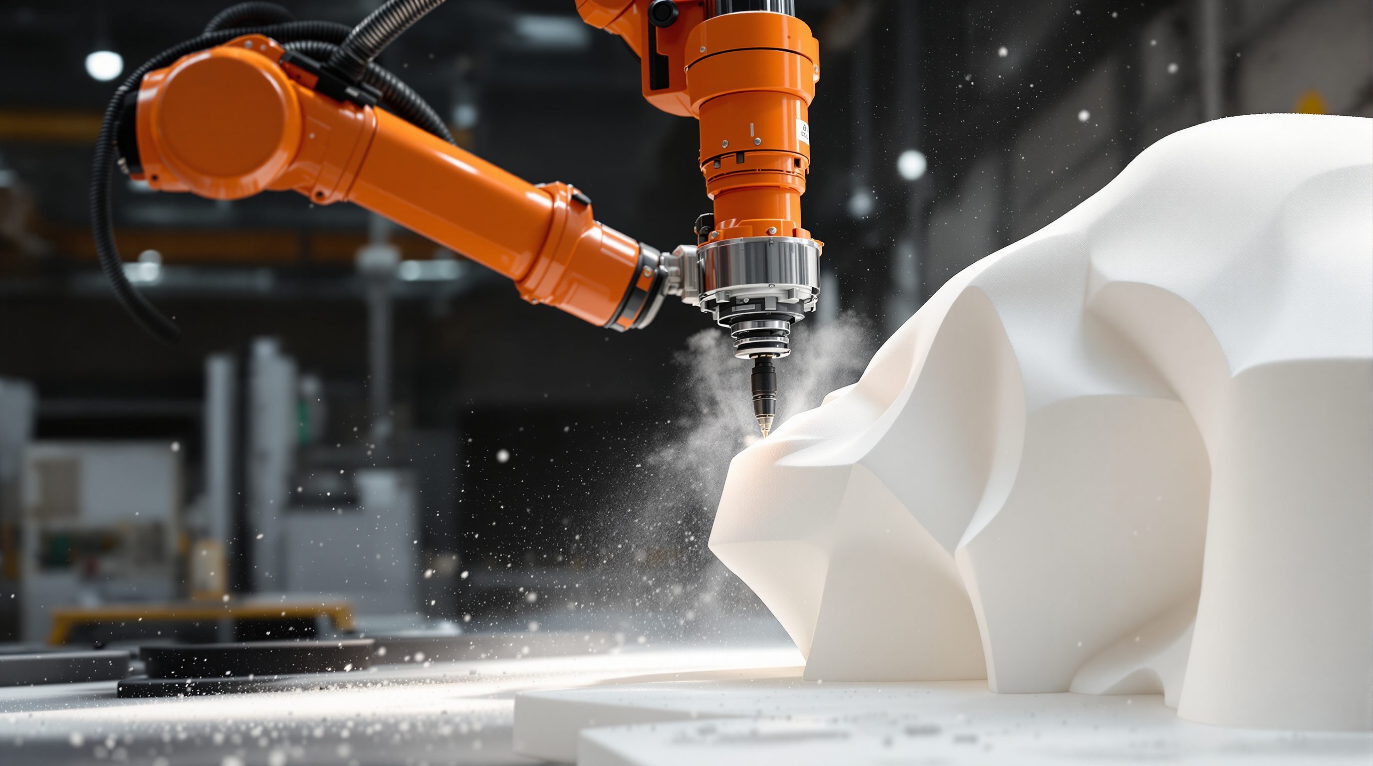
A gantry mill moves in a box. Bolt the same spindle to an arm and the tool can lean in from any angle - around undercuts, into deep pockets, along a twisting surface.
A CNC router is brilliant and blind: it can go anywhere inside its rectangular envelope, but the tool almost always points straight down. Whole geometries - undercuts, steep side walls, doubly-curved surfaces - are simply unreachable. A six-axis robot removes that constraint. The same cutting spindle, the same end mill, but now the tool can approach the work from any orientation the arm can reach.
That is why robotic milling and cutting has become the workhorse of digital fabrication labs. It shapes foam moulds for concrete and composites, carves timber and stone, and - with a hot wire instead of a spindle - slices expanded polystyrene into formwork faster than any cutter can chip it. The trade is accuracy and rigidity: an arm flexes where a gantry stays rigid. Knowing when the arm wins, and when it does not, is the skill of this lesson.
Arm reaches where the box cannot. Wire for ruled, mill for free. Access over accuracy.
The arm as a subtractive machine
Strip away the mystique and a milling robot is a familiar thing: an industrial six-axis arm - a KUKA, an ABB, a Staubli - with a cutting spindle bolted on as its end-effector instead of a gripper. It reads the same kind of instructions as any CNC machine (positions, feed rates, spindle speeds), generated by CAM software and posted to the robot controller. The material is removed exactly as on a router: an end mill spins at speed while the tool follows a toolpath, taking off chips pass by pass until the block becomes the part.
What changes is the geometry of access. A three-axis gantry router moves the tool in X, Y and Z but cannot tilt it; the cutter points down and stays down. A five-axis machine adds two rotary axes and can tilt within a limited cone. A six-axis robot can bring the tool in at essentially any orientation its joints allow, and its arm can reach around a part rather than only down onto it. That freedom is why robots dominate the milling of large, sculptural, deeply-curved forms.
The price is rigidity. A gantry is a stiff steel box; a robot is a chain of six motorised joints, and every joint has a little compliance. Push a cutter hard into steel and the arm deflects - fractions of a millimetre, but enough to matter. So robotic milling lives happily in soft and medium materials - rigid foam, timber, plaster, soft stone, some composites and plastics - and treats hard metals with caution, light cuts and slow feeds.
Same spindle, same G-code idea. The arm just points the tool anywhere the joints reach.
Milling foam, wood and stone
The single most common robotic-milling job in architecture is rigid foam - EPS and the denser XPS. It cuts like butter, so the arm can take huge, fast passes, and the result is a full-size mould. Cast concrete or spray a composite skin against a milled-foam mould and you get doubly-curved panels - GRC facade elements, seating, monuments - at a cost that would be impossible with hand-built formwork. A designer roughs the block with a large ball-nose cutter at a coarse stepover (the sideways bite between passes, maybe 10-15 mm) to remove bulk fast, then finishes with a fine stepover of 1-2 mm for a smooth ruled or free surface.
Timber is next. Robots carve joinery, mould-like patterns, relief panels and sculptural columns; the arm angle lets a cutter follow the grain of a twisting form or reach into a deep coffer. Hardwood needs sensible feeds and a rigid setup, because here the arm's compliance shows. Stone - marble, limestone, sandstone - is milled with diamond tooling and water cooling; it is slow and abrasive, but robots have revived architectural stone carving, roughing a block from a scan or model before a mason finishes by hand. Across all three the mindset is the same: rough pass to remove bulk, finish pass for surface, and let the six axes reach the angles a router cannot.
The tooling logic is worth internalising because it governs both time and quality. A ball-nose cutter leaves scallops - little ridges between passes whose height depends directly on the stepover; halve the stepover and you roughly halve the scallop height, but you double the number of passes and therefore the time. So finishing a large foam mould to a glass-smooth surface can take many hours even though roughing took minutes. Feed rate (how fast the tool travels through material) and spindle speed are matched to the material: foam tolerates aggressive feeds, hardwood and stone demand restraint. And because the arm can angle the tool, you can keep the cutter's most effective cutting zone on the surface even on steep walls, where a straight-down router would be dragging its tip and burning the finish. This is the quiet craft of robotic milling - not the exotic robot, but the same speeds-and-feeds and roughing-and-finishing discipline every machinist knows, now applied through six axes of freedom.
Hot-wire and hot-blade cutting
Milling foam removes material as dust and chips - clouds of it. There is a faster, cleaner way to shape EPS: hot-wire cutting. Instead of a spindle, the end-effector carries a taut wire (or a rigid hot blade) heated electrically to a few hundred degrees. It does not cut - it melts a thin slot through the foam as the arm sweeps it. A single pass can slice through a metre of polystyrene in seconds, with almost no debris and a smooth, sealed face.
The geometric catch: a straight wire can only sweep a ruled surface - a surface you could make by moving a straight line through space. Planes, cones, cylinders, hyperbolic paraboloids and gentle twists are all ruled and cut beautifully; a bulging double curve is not, and needs milling instead. This is exactly why hot-wire robots are the darling of concrete formwork: many elegant column, beam and panel moulds are ruled surfaces, and an arm can carve a whole EPS formwork block in a fraction of the time a mill would take, then the block is cast against and stripped away. A hot blade - an elastically bent, heated strip - extends this to smooth, tangent-continuous curved cuts, a technique developed at ETH Zurich for exactly this formwork use. The wire has a kerf too: the melted slot is a millimetre or two wide, and you offset the path to keep the finished face on size.
Wire melts, spindle chips. A straight wire only makes ruled surfaces - plan for that.
Accuracy, rigidity and the honest trade
Here is the sober part. A good gantry CNC holds a few hundredths of a millimetre across its bed. A six-axis milling robot, out of the box, is far less accurate - its absolute accuracy (how close it gets to a commanded point in space) can be a millimetre or more, even though its repeatability (returning to the same point again) is excellent, often under a tenth of a millimetre. The difference comes from the arm's kinematics: small errors in six joint angles compound along a long lever, and cutting forces flex the structure.
Labs fight this in three ways: calibration (measuring the real arm and correcting its model), stiff, shallow toolpaths (small radial and axial cuts so forces stay low), and external metrology - a laser tracker watching the tool and feeding corrections back. For most architectural work the honest answer is simpler: choose robotic milling where a millimetre is fine (foam moulds, sculptural timber, rough stone) and reach for a gantry or a dedicated 5-axis machine where tenths matter (precision joinery, metal, mould tools). And treat safety seriously - a spinning cutter or a heated wire on a fast, powerful arm is dangerous; robotic cells are fenced and interlocked, and you never share the workspace with a running industrial arm without proper guarding and training.
There is one more honest limit worth naming: the workspace is not a tidy box. A gantry's reachable volume is a simple rectangular prism, easy to reason about. An arm's is an awkward, roughly spherical shell with dead zones - places it physically cannot reach, and singularities, special poses where the arm loses a degree of freedom and can lurch or stall. Good CAM for robots simulates the whole arm through every move to catch reach limits, self-collisions and singularities before the spindle ever spins. So the workflow gains a step the gantry never needed: you do not just generate a toolpath, you verify that this particular arm, from this particular mounting, can actually execute it safely end to end. That verification is where a lot of robotic-milling expertise really lives.
Six-axis robot (KUKA / ABB)
An industrial arm used as a milling or cutting machine
Six motorised joints let the end-effector reach almost any position and orientation - the reach and angle a 3-axis gantry lacks.
End mill / spindle end-effector
The rotating cutter bolted on in place of a gripper
Removes material as chips exactly as on a router; foam and timber are friendly, hard metals are risky because the arm flexes.
Hot-wire / hot-blade cutting
Melting a slot through EPS foam with a heated wire or blade
Fast, clean and debris-free, but a straight wire only makes ruled surfaces; ideal for concrete formwork. Kerf offset applies.
Repeatability vs absolute accuracy
Returning to the same point vs hitting the true commanded point
Robots excel at the former, struggle at the latter; calibration and light cuts narrow the gap for architectural tolerances.
Workshop — decide milling vs hot-wire, arm vs gantry
You do not need a robot to build the judgement that drives one. This exercise trains the two decisions a milling robot forces: which cutting method, and whether an arm is even needed.
Paper and a notebook are enough. A robotic milling cell or hot-wire setup in a fablab or university lab makes the ideas concrete, but only under supervision - running spindles and heated wires on industrial arms is fenced, interlocked and trained work.
Goal: match a form to the right subtractive process
Inputs: three curved objects or images (a straight-tapered column, a smooth double-curved shell, an undercut bracket) and a notebook
Time: ~30 minutes
- 1For each form, ask first: is the surface ruled or free? Could you sweep a straight line through space to make it (ruled - a cone, twist, or planar taper) or does it bulge in two directions at once (free)? Ruled forms are hot-wire candidates; free forms must be milled.
- 2Now ask: does the tool need to reach an undercut or steep side wall? If it only needs to come straight down, a 3-axis gantry may do; if it must lean in from an angle or swing around the part, you need a multi-axis arm.
- 3Sketch a rough toolpath for one milled form: a coarse roughing pass (big ball-nose, wide stepover to remove bulk) then a fine finishing pass (small stepover for surface). Note roughly how the finish time grows as stepover shrinks.
- 4For the hot-wire candidate, draw the straight wire and the path it sweeps. Mark where a kerf offset would move the path to keep the face on size, and note where a hot blade (curved cut) would beat a straight wire.
- 5Write one honest line per object: which machine, why, and what tolerance you would trust it to - proving you chose access and method deliberately, not by default.
You’ll walk away with
A one-page decision sheet for three forms: ruled-or-free, arm-or-gantry, rough-and-finish plan, and the tolerance you would trust - the reasoning a fabrication specialist does before cutting anything.
Three altitudes on the same idea
Read the band that fits you — or all three.
Robotic milling is how ambitious form gets a mould. Doubly-curved GRC panels, sculptural concrete columns, cast facade elements - all begin as a milled-foam or hot-wire-cut EPS mould that only a multi-axis arm can shape economically. You do not need to run the robot, but knowing that ruled surfaces cut cheaply on a hot wire while free double-curves need milling will shape how you draw the thing in the first place.
This is bespoke, sculptural and one-off at interior scale. A carved timber reception desk, a milled-foam pattern for a cast plaster ceiling rose, a stone basin roughed from a block - robotic milling brings the angled, undercut, deeply-curved geometry that a flat router cannot reach. Specify it where the form genuinely curves in more than one direction; for flat, slotted or straight-sided work a laser or 3-axis CNC is faster and cheaper.
Learn to read a form and name its family before you touch a robot. Is this surface ruled (a hot wire will slice it) or free (it must be milled)? Does the tool need to reach an undercut (arm) or only straight down (gantry)? A milling robot is just a spindle on a six-axis arm running CAM toolpaths - the concepts are the same CNC ideas from earlier modules, now free to point anywhere. Master the vocabulary and the machine stops being intimidating.
“A milling robot is more accurate than a normal CNC router because it is a fancy industrial robot.”
Do it yourself
No machine - reason it through.
- 1What does a six-axis arm give a milling setup that a 3-axis gantry cannot?
- 2Why is robotic milling happier in foam and timber than in steel?
- 3What kind of surface can a straight hot wire cut, and what kind can it not?
- 4Explain the difference between a robot's repeatability and its absolute accuracy.
- 5For a smooth doubly-curved concrete panel mould, would you hot-wire it or mill it, and why?
The one line to carry out
Peer-reviewed journals & authoritative standards
- 01Association for Robots in Architecture — Robots in Architecture, 2026.
- 02Milling (machining) — Wikipedia, 2026.
- 03Robot end effector — Wikipedia, 2026.
- 04KUKA - industrial robotics — KUKA, 2026.
Removing material is only half of what an arm can do. Next we turn the tool around: instead of a spindle that cuts, a gripper that places - and discover that assembly is where robots may matter most in construction.
The author
Amogh N P
Architect, interior designer, and creative polymath. Studio Matrx began in his notebooks — his vision of design made honest, useful, and open to everyone. Its Academy is written and taught in his memory, and free, forever.
More about Amogh →