
 Lesson 6.1
Lesson 6.1 · Robotics Fundamentals
The Robotic Arm
Why architecture adopted a general-purpose 6-axis arm - and what it actually is
A CNC mill can only mill. A robot arm can mill, print, place, weld, cut and stack - because the arm is not the tool. It just holds one.
Every other machine in this course is built around a single job: a laser cuts, a printer prints, a router routes. The industrial robot arm is different in kind. It is a general-purpose positioning device - six motors that place a mounting flange anywhere within reach, at any angle - and it does not care what you bolt to that flange.
That one idea is why architecture, of all fields, fell for the robot. A discipline that makes thousands of different things - screens, moulds, brick walls, timber joints, foam formwork - could not justify a bespoke machine for each. One arm, many tools, endlessly reprogrammed, could. This lesson is about what that arm actually is before we make it fabricate anything.
The arm holds the tool; the tool does the work. Six axes = any point, any angle. Fence the whole reach.
Borrowed from the car factory
The 6-axis industrial robot was not invented for architecture. It was perfected over decades on automotive lines, where the same arms spot-weld, glue, handle and paint car bodies millions of times with brutal reliability. Names you will meet - KUKA, ABB, FANUC, Yaskawa - are industrial giants; Universal Robots (UR) popularised the smaller, safer collaborative arm. Architecture simply adopted this mature, cheap-because-mass-produced hardware and pointed it at new problems.
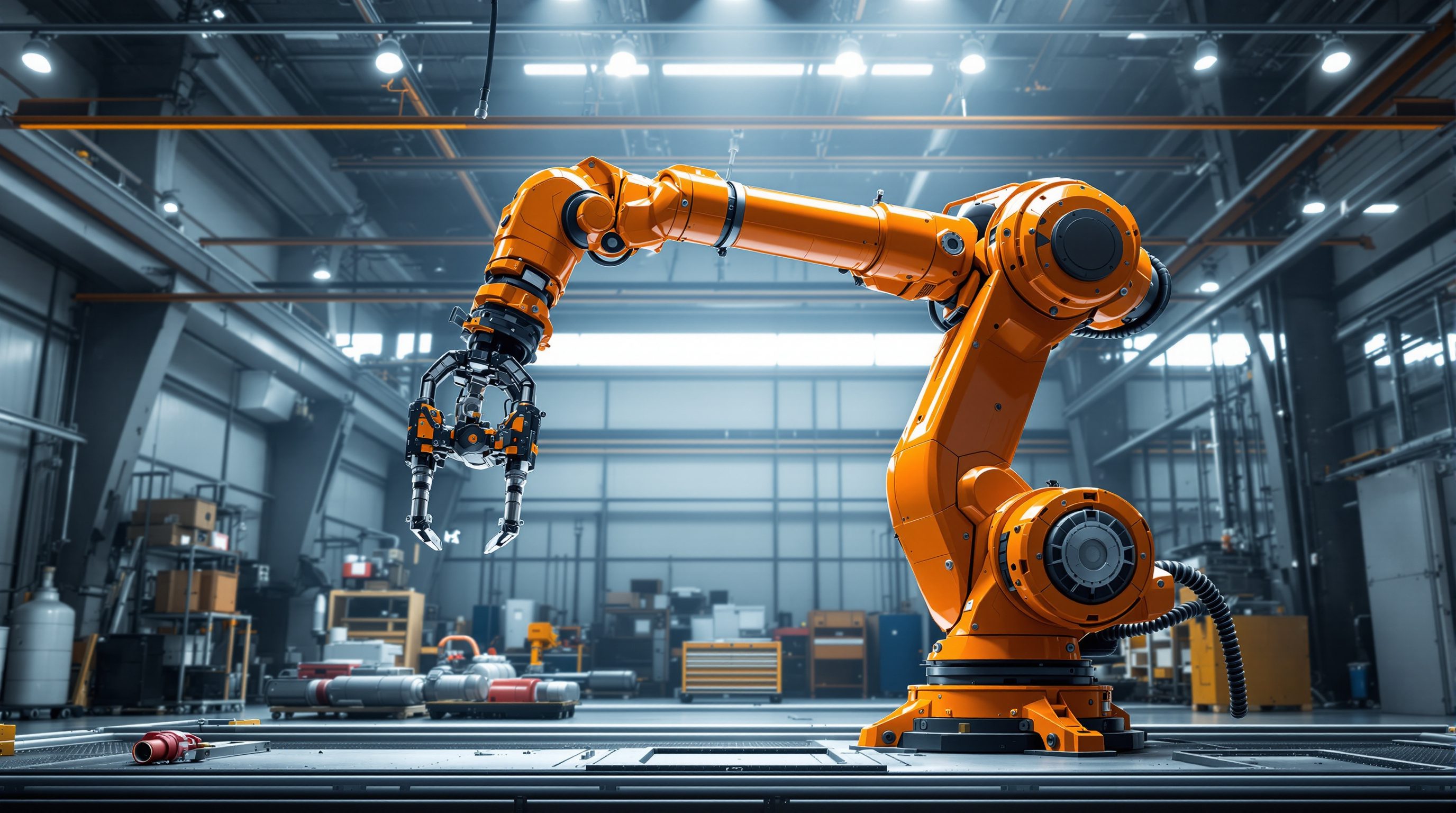
What architecture borrowed is specifically the articulated arm: a chain of rigid links connected by six rotary joints, mounted on a fixed base, ending in a tool-mounting flange (also called the end-of-arm plate). Count the joints and you have the '6-axis' name. Six is not arbitrary: three joints position the wrist anywhere in a volume, and three more orient the tool to any angle at that point. Fewer axes and you lose orientations; that full six-degrees-of-freedom capability is exactly what lets a robot approach a workpiece the way a craftsperson's hand would - from any side, at any tilt.
Links + 6 rotary joints + a flange. Bolt any tool to the flange. That is the whole machine.
Why general-purpose beat task-specific
Compare the robot to the CNC machines of Module 3. A gantry CNC router is rigid, accurate and fast - but it is a box that moves a spindle in X, Y and Z, and it will only ever do that. Its geometry is its destiny. The robot trades some of that rigidity and absolute accuracy for something architecture values more: reconfigurability. Monday it mills foam; Tuesday, with a new end-effector and a new program, it stacks bricks; Wednesday it prints clay. No other machine flexes across the subtractive, additive, formative and assembly families with a tool swap.
That flexibility is why research labs like ETH Zurich (Gramazio Kohler), ICD Stuttgart and the Association for Robots in Architecture built a whole field on the standard industrial arm rather than commissioning custom machines. The honest trade-off: a robot is typically less accurate than a good CNC (repeatability often around a tenth of a millimetre, but positional accuracy across the whole envelope is looser), less stiff against cutting forces, and far harder to program. You choose a robot when the job needs its reach, its angles or its versatility - not when a dedicated machine would simply do it better. Put bluntly: if a laser or a 3-axis router can make your part, use the laser or the router; reach for the arm when the geometry, the orientations or the sheer range of processes leaves you no simpler option.
CNC = one job, done superbly. Robot = many jobs, done well enough. Pick for the problem.
The three numbers that define an arm: payload, reach, repeatability
Every industrial arm is specified by three headline figures, and reading them is the first practical skill. Payload is the mass the arm can carry at full extension - including the end-effector itself, not just the workpiece. A 10 kg-payload arm sounds ample until your spindle-plus-mount weighs 7 kg, leaving 3 kg for the job. Architectural arms range from a few kilograms (a UR5, ~5 kg) up to heavy KUKA or ABB models carrying hundreds of kilograms.
Reach is how far the tool centre can get from the base - roughly the radius of a hemisphere. A common lab arm reaches around 2 to 2.7 metres; big arms exceed 3 metres, and mounting the robot on a linear track (a 7th axis) or a gantry extends that indefinitely along a wall or table. Repeatability is how precisely the arm returns to the same commanded point, typically +/- 0.03 to 0.1 mm - excellent, and often confused with accuracy, which is how close it gets to a new point it has never visited and is usually worse. A worked read: a 'KUKA KR 60, 2.03 m reach, 60 kg payload, +/- 0.06 mm repeatability' arm will hold a router steadily across a two-metre panel and come back to a drilled hole almost perfectly - but do not assume the first cut lands exactly where your model says without calibration.
Two more specs quietly matter. Stiffness - how much the arm deflects under load - is where robots trail CNC machines: push a spindle into hardwood and the arm flexes a little, so heavy cutting is done in light passes rather than one deep bite. And speed / duty cycle - the automotive heritage means these arms run reliably for years of continuous shifts, which is why a mass-produced industrial arm is cheaper and more dependable than any bespoke machine architecture could commission. Read all five together - payload, reach, repeatability, stiffness, duty - and you can tell at a glance whether an arm suits milling foam (easy), milling steel (no), or laying brick all day (yes).
Payload includes the tool. Reach sets the envelope. Repeatability is not accuracy.
The arm is dangerous - the cell is the machine
An industrial robot is a heavy, fast, powerful machine that will move exactly where told with no awareness of a person in its path. A standard arm can swing a multi-kilogram tool through a two-metre arc faster than you can step back, and it does not stop because you are there. This is the single most important thing to internalise in this module: the hazard is not just the robot, it is the entire volume its tool can sweep - the reach envelope. Treat every point the tool can reach as live.
So you never run a bare industrial arm in a shared space. It lives in a cell: a guarded zone with physical fencing or light curtains, an interlocked gate that stops the robot if opened, and emergency stops within reach. Collaborative robots (cobots) like the UR series are force-limited and designed to work near people, which relaxes some guarding - but only after a proper risk assessment, and a cobot swinging a spinning router or a hot extruder is no longer safe to touch regardless of its rating. All robot work in this course assumes trained, supervised operation inside a properly guarded cell. When we make the arm fabricate in later lessons, this cell is the unspoken frame around every exercise.
The hazard is the whole reach envelope, not the robot body. Fence it. Interlock it. E-stop it.
Beyond the single arm: tracks, gantries and other robot types
The bare arm is not the end of the story - how you mount it multiplies what it can do. The most common extension is a linear track (a 7th axis): the whole robot rides on a rail, so an arm with a two-metre reach can work along a ten-metre timber beam or a whole wall of brick. Architecture loves this because buildings are bigger than any arm's envelope. Arms are also mounted inverted (hung from a gantry or ceiling) to work down onto a large table, mounted on gantries for wide-span coverage, or paired as multi-robot cells where two arms cooperate - one holding a part while the other works it. Each of these is still the same six-axis logic; you are just changing where the base sits and how far it can travel.
The articulated 6-axis arm is also not the only robot morphology, and knowing the family helps. SCARA robots (a few axes, fast, rigid, working mostly in a horizontal plane) dominate flat pick-and-place. Delta robots (spider-like, three arms to a shared platform) are blindingly fast but limited in reach and orientation - think high-speed sorting. Cable-suspended and mobile robots are the frontier for on-site construction, where a fixed base is impossible: a robot that drives around a site, or hangs from cables over a large area, to print or place at building scale. For architectural fabrication, though, the versatile 6-axis arm - optionally on a track - remains the default, precisely because its full orientation freedom suits the endless variety of building components. When you scope a job, 'which arm' is really two questions: which arm, and mounted how.
Put the arm on a track and its reach covers a whole wall. SCARA, delta, mobile - each a different trade-off.
6-axis industrial robot
An articulated arm with six rotary joints and a tool flange
The workhorse of robotic fabrication (KUKA, ABB, FANUC, Yaskawa). Six axes give full position + orientation freedom.
Payload / reach / repeatability
The three headline specs of any arm
Payload includes the end-effector; reach is the envelope radius; repeatability (not accuracy) is how well it returns to a taught point.
Collaborative robot (cobot)
A force-limited arm designed to work near people
Universal Robots (UR) style. Safer by design, but a cobot carrying a spindle or hot tool still needs a risk assessment.
Robot cell / guarding
The fenced, interlocked, e-stopped zone around a running arm
The real 'machine' is the cell. The hazard is the whole reach envelope, not just the robot body.
Workshop - read an arm from its datasheet
Before you ever touch a robot you should be able to read one on paper. Robot makers publish full datasheets; learning to interpret three numbers and one diagram tells you what a given arm can and cannot do for a job.
A manufacturer datasheet (free online), paper and a scale rule. No robot required. Any hands-on jogging must be supervised in a guarded lab cell.
Goal: scope a real arm against a real task
Inputs: any manufacturer datasheet (KUKA, ABB or UR site) + a task in mind
Time: ~30 minutes
- 1Pick one arm from a manufacturer site (for example a KUKA KR series, an ABB IRB, or a UR10). Write down its payload, reach and repeatability from the datasheet.
- 2Sketch its work envelope roughly to scale - the hemisphere-ish reach around the base. Mark where a 1.2 m x 2.4 m sheet would sit and shade what the tool can and cannot reach without a 7th-axis track.
- 3Choose a task (mill a foam mould, lay bricks, print clay) and estimate the end-effector mass. Subtract it from the payload - what is left for the workpiece or the cutting forces? Is the arm big enough?
- 4Draw the cell around it: fence line, gate with interlock, e-stop positions, and the full swept reach envelope you must keep clear. Label the operator's safe position.
- 5Write two sentences: is this arm right for this task, and what is the limiting factor - payload, reach, repeatability or safe access?
You’ll walk away with
A one-page arm-scoping sheet: the three specs, a to-scale envelope sketch with a workpiece in it, a payload budget, and a cell layout with guarding and e-stops marked - plus your go / no-go verdict.
Three altitudes on the same idea
Read the band that fits you — or all three.
A robot arm is how bespoke, non-standard construction geometry gets made at scale. Timber joints milled from any angle, brick facades laid to a parametric pattern, foam formwork for curved concrete - jobs no single-purpose machine covers. You rarely buy an arm; you brief a fabricator or lab that has one. Knowing payload, reach and repeatability lets you scope what is buildable and ask the right questions.
The arm extends bespoke fabrication past the flat-sheet world. A robot can carve a solid-timber reception desk, hot-wire a sculpted foam feature wall, or place tiles to a gradient pattern - three-dimensional, from any direction, at furniture and feature scale. You will commission this through a specialist workshop; understanding the arm as a tool-holder helps you judge what a maker can and cannot promise.
Robotics is the most eye-catching skill on a fabrication portfolio - and the most misunderstood. Employers do not want someone who can push play; they want someone who understands the arm as a positioning device, respects the cell, and can reason about reach and payload. University labs and the Association for Robots in Architecture are where you get supervised hands-on time. Learn the fundamentals here so that time counts.
“A robot arm is just a more advanced CNC machine - basically a fancy 3D printer or mill.”
Do it yourself
No robot needed - reason it through.
- 1In one sentence, why is a robot arm called a general-purpose machine while a CNC mill is not?
- 2What do the three numbers payload, reach and repeatability each tell you?
- 3Why is repeatability not the same as accuracy?
- 4What exactly is the 'reach envelope' and why is it the real hazard?
- 5Name one job a robot arm does well that a fixed 3-axis CNC cannot, and say why.
The one line to carry out
Peer-reviewed journals & authoritative standards
- 01Industrial robot — Wikipedia, 2026.
- 02KUKA - industrial robotics — KUKA, 2026.
- 03ABB Robotics — ABB, 2026.
- 04Association for Robots in Architecture — Robots in Architecture, 2026.
If the arm is six joints placing a tool in space, the obvious question is how those joint angles turn into a precise tool position - and back again. That is kinematics, and it is next.
The author
Amogh N P
Architect, interior designer, and creative polymath. Studio Matrx began in his notebooks — his vision of design made honest, useful, and open to everyone. Its Academy is written and taught in his memory, and free, forever.
More about Amogh →