
 Lesson 3.2
Lesson 3.2 · CNC Milling & Routing
Multi-Axis Machining
How 4- and 5-axis machines tilt the tool to reach undercuts and flowing surfaces
A 3-axis tool can only ever come straight down. Give it two more axes and it can tilt, reach around corners, and touch surfaces that were impossible before.
Three axes trace any path from above. That covers most work, but it hits a hard wall the moment geometry hides beneath an overhang, or a surface curves so steeply that a vertical tool can no longer sit against it. The tool simply cannot reach.
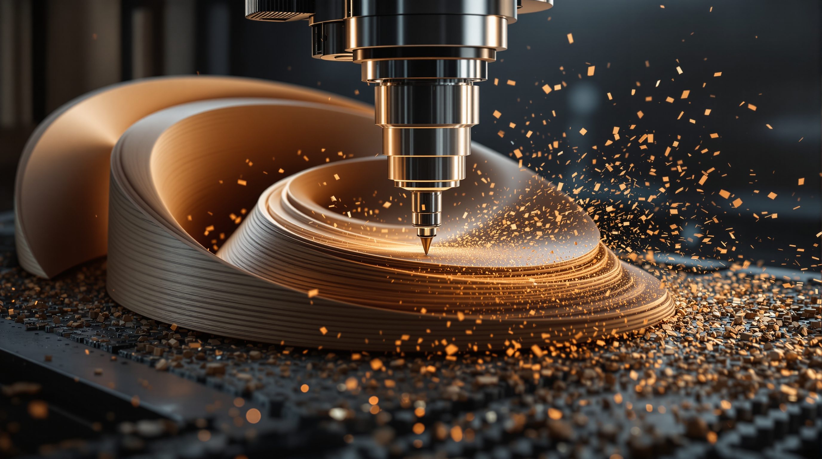
Multi-axis machining removes that wall by letting the tool - or the part - rotate. Add a fourth axis and the work can spin under the cutter; add a fifth and the spindle can also tilt, so the tool can approach from almost any direction. The payoff is undercuts, deep pockets, propeller-like blades and seamless double-curved surfaces in one setup. The cost is money, programming difficulty and the ever-present risk of the machine colliding with itself.
Rotation buys direction. Undercuts need tilt. Prefer 3+2; pay for continuous only when the surface demands it.
From three axes to four and five
A 3-axis machine has three linear axes: X, Y, Z - straight-line moves. Multi-axis machines add rotary axes on top. A 4-axis machine adds one rotation, usually called A (a rotation about the X axis): picture a horizontal rod chucked at both ends that can turn the workpiece over, so the tool can machine around a cylinder or index a part to a new face. It is common for turning a blank to carve columns, balusters, table legs and 3D-around-the-side work.
A 5-axis machine adds two rotary axes (commonly A and B, or B and C). Those two rotations mean the relationship between tool and surface can be set to almost any angle. Crucially, five axes is the magic number for surfaces: with two rotations plus three translations, the tool can be positioned and oriented anywhere in the working volume, so its tip can touch and its side can lie against a freeform surface from the best direction. The rotation can live on the table (the part tilts and turns, common on smaller machines), on the head (the spindle tilts and swivels, common on big-gantry and robotic setups), or split between the two. Either way the effect is the same: the tool is no longer stuck coming down from directly overhead.
3 linear axes + 1 rotary = 4-axis. + 2 rotary = 5-axis. Rotation is what buys you direction.
Reaching the undercut
The clearest reason for extra axes is the undercut - any feature that tucks back underneath something above it, so a vertical tool is physically blocked. Think of a lip curling under a moulding, a T-slot, the hollow beneath a chair arm, a gargoyle mouth, or the negative draft of a decorative cornice. A 3-axis tool coming straight down hits the overhang before it ever reaches the hidden surface. The only 3-axis workarounds are ugly: split the part into pieces, flip and re-fixture it several times (losing accuracy each time), or redesign the undercut away.
Five axes solves it directly. The head (or table) tilts so the tool approaches from the side, slips under the overhang, and machines the undercut cleanly in a single setup. Fewer setups is itself a huge win: every time you unclamp and re-clamp a part you introduce error, so machining a complex piece in one setup rather than five is both faster and far more accurate. There is a second, subtler benefit for curved surfaces: on a 3-axis machine, a ball-nose bit finishes a steep surface with only the very tip of the ball - the slowest-cutting, poorest-finish point of the tool. A 5-axis machine can tilt the bit so it cuts on the side of the ball where the surface speed is higher, giving a better finish faster. It can also keep a shorter, stiffer tool at a constant angle to a deep or steep surface, so the cutter does not have to reach in with a long, flexing overhang - which again means less chatter and a cleaner result. Reach and finish quality both improve.
Indexed versus continuous 5-axis
Not all 5-axis work is equally hard, and the distinction is essential. Indexed 5-axis - also called 3+2 machining - locks the two rotary axes at a fixed angle, then does ordinary 3-axis cutting on the presented face. Machine one face, stop, rotate the part to a new fixed angle, lock, machine again. The two extra axes only position the work; they do not move while cutting. This is by far the more common mode, because it is nearly as easy to program as 3-axis work, it is rigid (the locked axes do not flex), and it handles a huge range of jobs: prismatic parts with features on several faces, undercuts reachable from a set angle, moulds with drafted walls. Most shops that own a 5-axis machine spend most of their time in 3+2.
Continuous (or simultaneous) 5-axis is the hard mode: all five axes move together, in a coordinated flow, while the tool is cutting. This is what you need for genuinely freeform double-curved surfaces - turbine blades, propellers, sculpted architectural panels, complex moulds - where the tool must continuously re-orient to stay tangent to a surface that curves in every direction. It produces seamless results but demands sophisticated CAM, careful collision checking, and a machine (and operator) that can be trusted with all five axes live at once. The honest rule: reach for indexed 3+2 whenever the geometry allows it, and only pay the continuous-5-axis tax when the surface genuinely demands it.
3+2: lock, cut a face, re-index. Continuous: all five move while cutting. Prefer 3+2 unless the surface forbids it.
Programming, setups and the machine that moves
Multi-axis machining shifts the difficulty from the machine to the planning. The CAM software must now describe not only where the tool tip goes but how the tool is oriented at every moment, and it must guarantee that no part of the tool, holder, spindle or moving head ever strikes the part, the fixture or the machine as it swings around. That is why serious 5-axis CAM leans heavily on full machine simulation: an accurate virtual model of your specific machine, tool, holder and fixtures runs the whole program before any metal moves, checking for interference and reachability. Skipping that step is how expensive crashes happen.
Fixturing becomes a puzzle in its own right. To let the tool reach all around a part, you often cannot clamp it the obvious way - a clamp in the wrong place blocks the very access the extra axes were bought for. Solutions include holding the part on a small footprint, leaving it attached to the stock by a sacrificial stub that is cut away last, using custom jigs, or the one-setup ideal where the part is gripped once and machined on all its faces without re-clamping. Every avoided re-clamp removes a source of error, which is a large part of why 5-axis is prized for intricate parts: not just that it can reach, but that it reaches everything in a single, accurately-referenced setup. The lesson for a designer is that a multi-axis part is scoped as much by how it can be held and reached as by its final shape - and a good fabricator will think about the fixture before quoting the cut.
5-axis moves the hard work into planning: simulate for collisions, then fixture so the tool can reach all round in one setup.
When the complexity is worth it
Extra axes are not free, and more is not automatically better. A 5-axis machine costs far more than a 3-axis one; the CAM software is more expensive and harder to learn; programming takes longer; and every simultaneous move raises the chance of a collision - the tool holder, spindle nose or head crashing into the part or fixture - which good CAM simulates and checks for, but which remains a real risk. Setup and fixturing to give the tool clear access all round is its own puzzle. None of that is justified to cut a flat sheet of plywood.
So choose deliberately. Stay 3-axis when the work is sheet goods, flat or gently-curved parts, and anything reachable from above - which, in architecture and interiors, is most things. Step up to 4-axis when you are working around cylinders or need to machine several faces of a part - columns, turned elements, wrapping detail. Step up to 5-axis only when the geometry truly requires it: real undercuts, deep angled features that would otherwise need many setups, or continuously double-curved surfaces where finish quality matters. In practice, most 5-axis owners use the machine mainly in 3+2 indexed mode and save continuous machining for the few surfaces that demand it. The skill is not owning the fanciest machine; it is recognising which axis count a given part actually needs.
3-axis for most. 4-axis around cylinders. 5-axis for undercuts and freeform - and mostly in 3+2.
4-axis machining
Three linear axes plus one rotary
Adds a rotation (often A) so the work can turn under the tool - columns, turned parts and around-the-side features.
5-axis machining
Three linear axes plus two rotary
Two rotations let the tool reach and orient almost anywhere - undercuts, deep angled features, and freeform surfaces in one setup.
Indexed (3+2) machining
Rotary axes locked at a fixed angle while cutting
The common, easier mode: position the part at an angle, then cut in 3-axis. Rigid and near-3-axis to program.
Continuous / simultaneous 5-axis
All five axes moving together while cutting
Needed for freeform double-curved surfaces; powerful but demands advanced CAM, collision checking and skill.
Workshop — find the undercuts, choose the axis count
You do not need a 5-axis machine to learn its logic. This exercise trains the single most useful judgement: how many axes does a part actually need, and why?
Objects or 3D models, paper and pencil. Optional: CAM software to visualise reachability. Any actual 5-axis or robotic milling must be supervised by trained operators.
Goal: judge required axis count from geometry alone
Inputs: 3 objects or 3D models with varied form (one flat-ish, one turned/cylindrical, one with an undercut) + notebook
Time: ~30 minutes
- 1For each object, imagine a tool coming straight DOWN from above. Shade every surface the tool can reach that way - that is the 3-axis-reachable region.
- 2Circle every surface it CANNOT reach: anything hidden under an overhang, or too steep for a vertical tool. Label each an undercut.
- 3Decide the minimum axis count: fully reachable from above = 3-axis; wraps around a cylinder or needs several faces = 4-axis; has true undercuts or flowing double curves = 5-axis.
- 4For each 5-axis candidate, ask whether INDEXED 3+2 would do - could you reach every feature by locking the part at a few fixed angles? - or whether the surface genuinely needs continuous motion.
- 5Sketch one redesign that removes an undercut (split into parts, add draft, or reorient) so a cheaper machine could make it. Note what you would lose by doing so.
You’ll walk away with
For three objects, a marked-up analysis: 3-axis-reachable surfaces, circled undercuts, the minimum axis count with reasoning, an indexed-versus-continuous call, and one undercut-removing redesign. This is exactly how a fabricator scopes a job.
Three altitudes on the same idea
Read the band that fits you — or all three.
Multi-axis machining is what makes ambitious, non-orthogonal architecture physically cuttable. Sculpted GRC panels, complex timber joints in a robot-milled roof, moulds for double-curved concrete - these need a tool that can tilt in. You rarely program it yourself, but knowing what 3+2 versus continuous 5-axis costs lets you judge a fabricator quote and design geometry that stays affordable to make.
When a carved feature curls under itself, you have left 3-axis territory. A sculpted timber balustrade, a mould with an undercut relief, a solid form that tucks back on itself - these need multi-axis work and cost accordingly. Knowing this lets you decide early whether to embrace the expense or redesign the detail so a simpler 3-axis cut or a split-and-assemble approach can make it.
You will likely design for 5-axis long before you operate one. The key mental model to carry now is direction of approach: can a tool reach this feature coming straight down, or does it need to tilt in? Learn to spot undercuts in your own models and to prefer 3+2 solutions, and you will design parts that are genuinely machinable - a skill worth more than button-knowledge on any one machine.
“A 5-axis machine is just a better 3-axis machine - more axes are always better.”
Do it yourself
No machine needed - reason it through.
- 1What does a fourth axis add to a 3-axis machine, and what is it good for?
- 2Why is five the magic number of axes for machining freeform surfaces?
- 3Explain the difference between indexed 3+2 and continuous 5-axis machining.
- 4Give one reason fewer setups makes 5-axis machining more accurate, not just faster.
- 5Name a real risk that grows when all five axes move at once, and how CAM helps manage it.
The one line to carry out
Peer-reviewed journals & authoritative standards
- 01Milling (machining) — Wikipedia, 2026.
- 02Computer-aided manufacturing (CAM) — Wikipedia, 2026.
- 03CNC router — Wikipedia, 2026.
- 04Gramazio Kohler Research — Digital fabrication in architecture (ETH Zurich) — ETH Zurich, 2026.
Whatever the axis count, the machine still needs to know how fast to spin and how fast to move - get that wrong and you burn wood or snap the bit. The next lesson is feeds, speeds and toolpaths.
The author
Amogh N P
Architect, interior designer, and creative polymath. Studio Matrx began in his notebooks — his vision of design made honest, useful, and open to everyone. Its Academy is written and taught in his memory, and free, forever.
More about Amogh →