
 Lesson 1.4
Lesson 1.4 · Loads & Load Paths
Tracing the Load Path to the Ground
Every load, from a person's weight to a hurricane, must find an unbroken path down through the structure into the earth - and a structure is only as safe as the weakest link on that path
Somewhere below you, right now, your weight is travelling through a slab, into a beam, down a column and into the soil - and if any link in that chain were missing, you would already know.
Every load a building carries has to go somewhere, and there is only one destination: the ground. The load path is the route each load takes to get there - down through the slab it lands on, into the beam that gathers the slab, down the column that carries the beam, into the foundation that spreads the column's load, and finally into the soil, which pushes back up to hold the whole thing in equilibrium. It sounds obvious, and it is the single most important idea in all of structures.
What makes it powerful is its ruthlessness. The path must be complete and unbroken - every load must have a continuous route from where it is applied all the way to the earth, and every element on that route must be strong enough to carry what passes through it. A structure is only as safe as the weakest link on the load path. This final lesson of the module ties everything together: it traces the vertical path for gravity and the lateral path for wind and earthquake, explains why redundancy saves lives, and walks through a simple building from roof to soil.
Can you trace every load to the ground on your own drawing? If yes, you understand the building. If no, neither does it.
The vertical load path: gravity's journey down
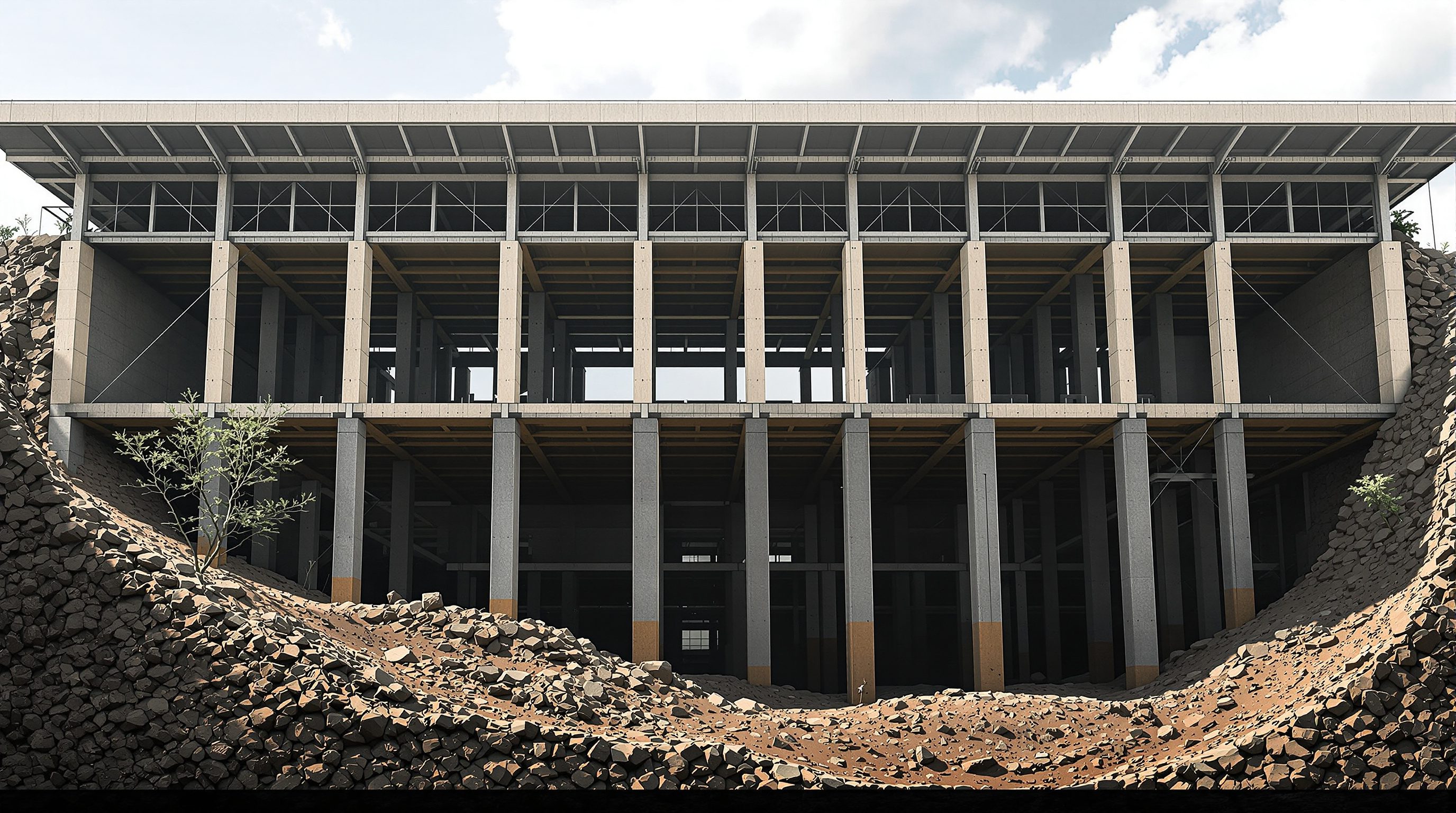
Start with gravity, because its path is the easiest to feel. Imagine standing in a room. Your weight, plus the weight of the floor finish and the slab beneath your feet, is a load. That load is carried first by the slab, which spans between its supports and delivers the load to their edges. The slab hands its load to the beams (or to load-bearing walls) at its edges. The beams, now carrying the slab's load plus their own weight, span to the columns and deliver everything to them. Each column gathers the loads from every floor above it and carries the accumulating total downward - which is why columns get more heavily loaded, and usually bigger, as you go down a tall building.
At the bottom, the column delivers its entire stacked load to the foundation, whose job is to spread that concentrated force out over enough area of soil that the ground can bear it without failing or settling excessively. The soil, finally, pushes back up with an equal reaction - and only when the upward reaction balances the downward load is the structure in equilibrium and standing still. That is the whole chain: load - slab - beam - column - foundation - soil - reaction, an unbroken sequence from the point of application to the earth.
Two truths fall out of this. First, each element must be sized for everything that passes through it, which accumulates downward - a ground-floor column carries far more than a top-floor one. Second, the path must be continuous: if a beam is not actually connected to its column, or a column does not sit over a foundation, the load has nowhere to go and the structure fails at that gap. Load does not care about intentions; it follows physics to the ground or it brings the structure down trying.
Load - slab - beam - column - foundation - soil - reaction. Follow it home, unbroken, every time.
The lateral load path: carrying the sideways push
Gravity's path runs conveniently downhill, but wind and earthquake push sideways, and a frame designed only to carry gravity straight down can be quite unable to resist a horizontal shove. The lateral load needs its own complete path to the ground, and it works differently - and understanding it is what separates a structurally literate architect from one who only sees the columns.
It begins at the floors. A wind pressure on a facade, or an inertia force born in the floor's own mass during an earthquake, is first collected by the floor plate acting as a diaphragm - a stiff horizontal plane that gathers the sideways force across the floor and carries it, like a flat beam lying on its side, to the vertical elements that can resist lateral load. Those vertical elements are the lateral-load-resisting system: shear walls, braced frames, or a moment-resisting frame (rigid beam-column joints), or a central core. They take the horizontal force the diaphragms deliver at each level and carry it down the height of the building, accumulating it just as columns accumulate gravity.
At the base, this accumulated horizontal force - and the overturning moment it creates, trying to tip the building over - is delivered to the foundation, which must resist both the sliding and the overturning by anchoring into the ground. The complete lateral path is therefore facade or mass - floor diaphragm - shear wall / brace / frame - foundation - soil. Every part must be continuous and connected: a shear wall that stops at the first floor, a diaphragm not tied to the wall, a brace with a weak connection - each is a break that leaves the sideways load stranded. This is exactly why the seismic 'soft storey' is so deadly: it is a break in the lateral path where a stiff wall system suddenly becomes bare columns, and the load, arriving, has nothing strong to travel through.
Weak links and redundancy: why robustness saves lives
Because the load path is a chain, it inherits the chain's brutal logic: it is only as strong as its weakest link. A beautifully sized column is worthless if the connection delivering load to it is weak; a strong shear wall is useless if the diaphragm feeding it is not tied to it. Many real failures are not failures of the big members at all but of the humble connections and transfer points between them - the joints, bearings, anchors and splices where load changes direction or hands off from one element to the next. An architect learns to be suspicious precisely at these hand-offs.
The defence against a weak link bringing down a whole building is redundancy - deliberately providing more than one path for the load, so that if one element or connection fails, the load can reroute through another rather than the structure collapsing. A frame with several columns and continuous beams is redundant: lose one column and the beams can, if designed for it, bridge over the gap and share the load among the neighbours. A structure with no alternative paths - where every element is essential and singular - is non-redundant, and the failure of any one piece is the failure of everything. This is the difference between a structure that is damaged and one that collapses.
The extreme failure to guard against is progressive (disproportionate) collapse: a local failure - one column lost to a vehicle impact, a gas explosion, a construction error - that cascades link by link into the collapse of a whole building, as happened notoriously at Ronan Point in 1968. The remedy is exactly redundancy and continuity: tie the structure together so it can span over a lost element, provide alternative load paths, and avoid designs where one member's loss is catastrophic. Codes increasingly require this robustness for larger buildings, and the IStructE has written extensively on it. For the architect, the lesson is to value continuity and alternative paths as safety, not as excess - a building that can lose a piece and still stand is a building that protects the people in it.
A chain fails at one link; redundancy gives the load a second road home. Continuity is safety.
A worked walk-through: one simple building
Let us trace a real load through a simple four-storey reinforced-concrete framed building, the kind on any Indian street. A person and their furniture stand in a second-floor room. Their weight, plus the finishes and the self-weight of the slab, is an imposed-plus-dead load spread over the slab. The slab spans about four metres between beams and carries this load to the beams on its edges. Each beam gathers a strip of slab load and its own weight and spans to the columns at its ends, delivering a concentrated reaction to each. So far this is the second floor only.
Now the accumulation. That second-floor column carries not just this floor's load but everything from the floors above it too, all stacked. It delivers the total to the column below, which adds the first floor, and so on, so that the ground-floor column carries the summed load of all four floors - which is why it is the fattest column in the building. It delivers everything to its footing, a spread pad that broadens the load until the pressure on the soil is low enough for the ground to bear. The soil reacts upward, and the gravity path is complete: person - slab - beam - column - column - column - footing - soil.
Now add wind. It presses on the building's face; each floor slab acts as a diaphragm, gathering the wind on that storey and carrying it to the building's shear walls or braced core. Those vertical elements carry the accumulating horizontal force down to the foundations, which resist the push (sliding) and the tip (overturning) by anchoring into the soil. Trace both paths on any building you design and you will immediately spot the danger points: a beam not aligned over a column, a shear wall that stops short, a long transfer beam carrying a column that was moved for a nicer plan, a connection asked to do too much. If you can trace every load to the ground on your own drawing, unbroken and through elements strong enough to carry it, you understand your structure. If you cannot, neither does the building.
Load-path thinking as a design habit
The load path is not just an analysis to be checked at the end; it is a way of designing from the start, and it is the single most useful structural habit an architect can build. Every time you move a column for a better plan, open a wall, cantilever a floor, stack a heavy room over a light one, or remove a support to make a space flow, you are editing a load path - and the load still has to reach the ground somehow. Sometimes the edit is free; sometimes it forces an expensive transfer structure (a deep beam or truss that catches a load and carries it sideways to a support that does exist), which is costly, deep and worth knowing you have triggered.
The discipline is to ask, of every move, a simple question: where does this load go now? If you remove the column under a corner, what catches the load above it? If you open this shear wall for a doorway, what carries the lateral force that wall was carrying? If you push this floor out as a cantilever, what balances it? Asking early, while the plan is still soft, lets you find an honest answer with the engineer rather than discovering an impossible one at tender.
This habit is also what makes the rest of this course legible. Every structural system you will meet - beams and slabs in Module 2, frames and walls and cores in Module 4, long-span and tall-building systems later - is ultimately a particular, clever answer to the same question this lesson has posed: how to gather loads and carry them, vertically and laterally, safely and efficiently, to the ground. Master the idea of the load path here, and you will read every one of those systems not as a mysterious assembly but as a route you can trace with your finger from the load in your hand all the way down to the soil.
IS 456 / IS 800
RC and steel design codes (India)
Size and connect the elements and joints along the load path; connection design is where many real failures hide.
Robustness / disproportionate collapse
Tying structures so local failure does not cascade
Codes require alternative load paths and continuity for larger buildings; the IStructE has led guidance on it.
Diaphragm action
Floor plate collecting and carrying lateral load
The horizontal link in the lateral path; must be tied to the shear walls, braces or frames it feeds.
NBC 2016 structural safety
Overarching Indian framework for structural design
References the load and material codes and the requirement for a complete, safe load path to the ground.
Workshop - trace both load paths through a building
This is the capstone skill of the module and the most useful structural drill you will ever run: taking a real building and following every load, vertical and lateral, all the way to the ground, spotting the weak links on the way.
Plans and a section of a building, coloured pens for the two paths, and paper. No analysis software needed - this is a tracing and reasoning exercise.
Goal: trace the complete gravity and lateral load paths of a building and find its weak links
Inputs: plans and a section of a simple framed building (yours, a studio project, or a case study)
Time: ~45 minutes
- 1Pick a point load - a person, a heavy machine, a water tank - on an upper floor. Trace its gravity path in words and arrows: slab to beam (or wall) to column, column to column down the height, to foundation, to soil, and note the upward soil reaction that closes the loop.
- 2Check accumulation and alignment: confirm each column sits over the one below and over a foundation, and note how the load grows downward so lower columns must be larger. Flag any column that is misaligned or lands on a beam (a transfer) rather than a foundation.
- 3Now trace the lateral path for wind or earthquake: show the force arriving at a facade or born in the floor mass, collected by the floor diaphragm, carried to the shear walls, braces or core, down them to the foundation, and resisted there against sliding and overturning.
- 4Hunt for weak links: mark every connection, transfer point and discontinuity - a shear wall that stops short, a diaphragm not tied in, a soft storey, a long transfer beam, an under-designed joint. Circle the single link you would most want the engineer to confirm.
- 5Test for redundancy: imagine losing one column or one wall. Can the load reroute through neighbouring elements, or does the structure have no second path? Write one sentence on how robust the building is and what one change would improve it.
You’ll walk away with
A one-page load-path study of one building: an annotated section tracing the gravity path from an upper-floor load to the soil and the lateral path from facade to foundation, with weak links circled and a short judgement on the building's redundancy and robustness.
Three altitudes on the same idea
Read the band that fits you — or all three.
Design with the load path live in your mind: every plan move edits a route to the ground. When you shift a column, open a wall, cantilever a floor or stack heavy over light, ask where the load goes now - and know when you have triggered an expensive transfer structure. Value continuity, alignment of columns floor to floor, and redundancy as safety, not waste. The ability to trace every load, vertical and lateral, to the ground on your own drawing is the core structural skill of an architect.
Read the load path before you open, remove or hang anything. That wall you want to take out may be carrying floors above; that beautiful clear span may depend on a column you were about to box in or move. Never cut a structural wall, beam or brace, or hang a heavy load from a slab, without knowing what that element carries and getting the engineer's confirmation. Learning to tell a load-bearing wall from a partition, and to spot a shear wall, is the interior designer's most valuable structural literacy.
Make tracing the load path your default drill on every project and precedent. For any building, follow gravity from a person on a floor down slab, beam, column, foundation to soil, then follow wind from the facade through the diaphragm and shear walls to the foundation. Learn to spot weak links - a stopped shear wall, a misaligned column, a soft storey, a lonely transfer beam - and to explain redundancy. This is the thread that ties every structural system in the rest of the course together.
“Once the columns and beams are strong enough, the building is safe - the loads will naturally find their way down through a strong structure.”
Do it yourself
Reason it through - no software needed.
- 1List the elements of the vertical gravity load path in order, from a person on a floor to the soil.
- 2List the elements of the lateral load path for wind, from the facade to the soil.
- 3Why is the ground-floor column usually the largest in a multi-storey building?
- 4Define redundancy in a structure and explain how it prevents progressive collapse.
- 5Give three places on a load path where a weak link commonly hides.
The one line to carry out
Peer-reviewed journals & authoritative standards
- 01IS 456: Plain and Reinforced Concrete - Code of Practice — Bureau of Indian Standards, 2000.
- 02IS 800: General Construction in Steel - Code of Practice — Bureau of Indian Standards, 2007.
- 03National Building Code of India 2016 (SP 7) — Bureau of Indian Standards, 2016.
- 04The Institution of Structural Engineers (IStructE) — IStructE, 2024.
- 05Building Structures Illustrated — Ching, F.D.K. (Wiley), 2014.
That completes Module 1: you can now name every load a building carries and trace each one to the ground. From here the course turns to how the elements on that path actually work - starting with how beams, slabs and columns carry load through bending, shear and compression.
The author
Amogh N P
Architect, interior designer, and creative polymath. Studio Matrx began in his notebooks — his vision of design made honest, useful, and open to everyone. Its Academy is written and taught in his memory, and free, forever.
More about Amogh →