
Fire Hydrants in India (2026): Internal Wet Risers, Yard Hydrants & Fire-Tender Connection
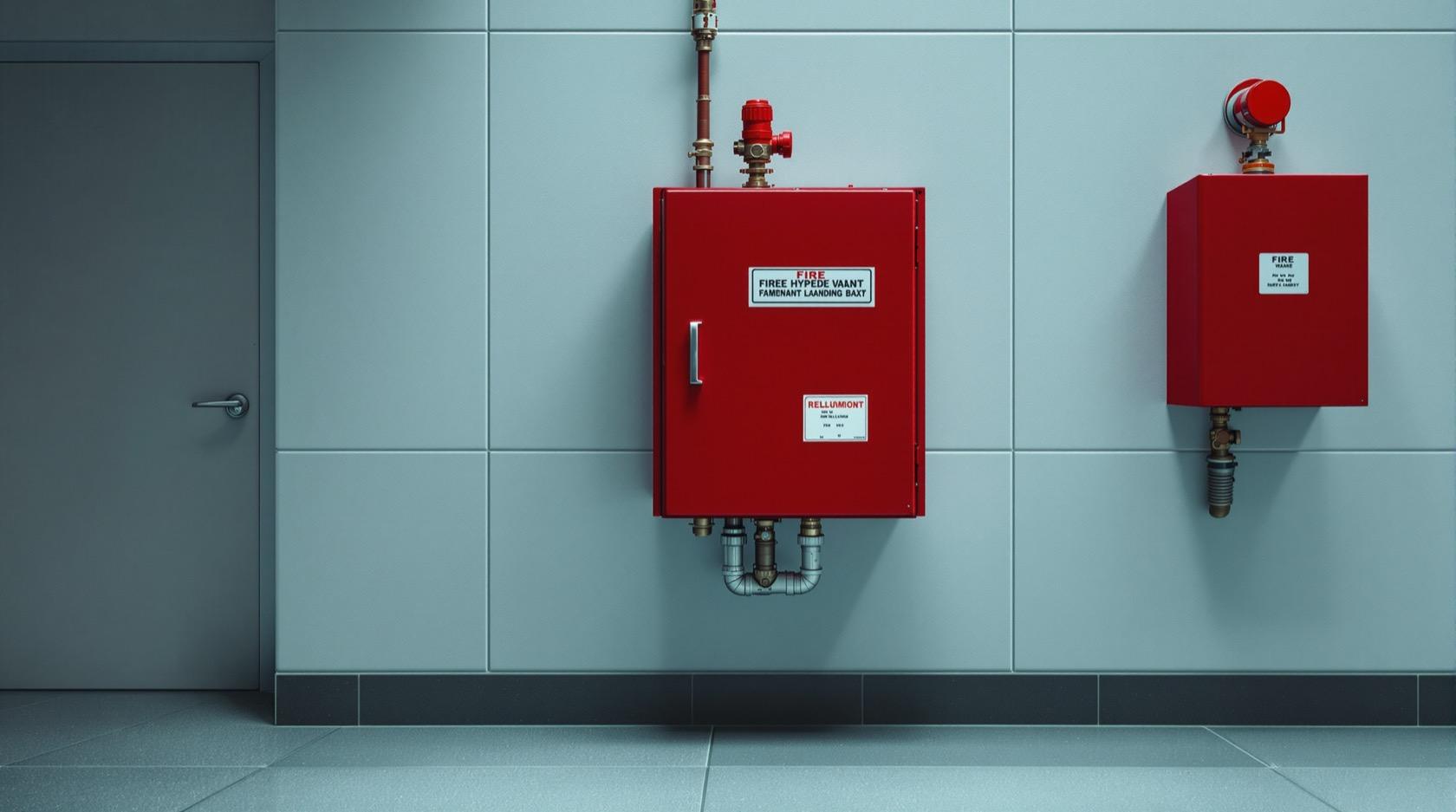
The building hydrant system is the high-pressure water network the fire brigade fights a serious fire with - the internal wet riser and landing valves, the external yard hydrants, and the fire-service inlet that lets a tender boost it.
When a fire outgrows a portable extinguisher and a hose reel, it is fought with water at pressure and in volume - and the network that delivers that water is the building fire hydrants system. This is the serious end of a building's fire-water defence: the high-pressure pipework, valves and outlets that a trained in-house fire team and, above all, the arriving fire brigade connect their hoses to in order to fight a developed fire. It has two halves that work together - the internal hydrant or wet riser that carries water up through the building to a landing valve in every stair lobby, and the external or yard hydrant that rings the building at ground level - plus the fire-service inlet through which a fire tender pumps its own water in to boost the whole system.
This is the hydrant chapter of Studio Matrx's fire-safety library, sitting under the complete guide to fire safety in India. It is written for the people who own, manage, develop and specify buildings - RWA committees, facility managers, builders, developers and the professionals who advise them - so you can understand what the hydrant system is for, what it needs to work, and how to keep it live. This guide is the delivery end of the story; the pumps that pressurise it and the tank that feeds it have their own chapters - the fire pumps and the fire-water tanks - and you should read all three together.
Scope and safety - read this first. A building fire hydrants system - the wet riser, the landing valves, the yard hydrants, the fire-service inlet, the pumps and the tank that feed it - is a statutory, engineered installation. Its hydraulic design, sizing, installation, commissioning and certification are the work of a licensed fire-protection engineer and contractor, tied to the National Building Code (via SP 7 : 2026, Part 4 Fire and Life Safety), the internal-hydrant code IS 3844 : 1989, the external-hydrant code IS 13039 : 2014, and your premises Fire NOC under the State Fire Services Act and Rules. This guide helps you understand, specify and maintain that system; it is educational guidance, not legal advice, and never a manual for operating hydrant valves in a fire. When a serious fire breaks out, one rule overrides everything below: get everyone out and call the fire brigade on 101 or 112 - fighting a developed fire from a hydrant is the trained fire team's and the brigade's job, not an untrained occupant's.
What a fire-hydrant system actually is
A hydrant system is not a single object; it is a plumbed water network under pressure, waiting. Trace the water and the whole thing makes sense. It starts at a dedicated fire-water tank holding a reserve that is kept for firefighting and nothing else. From the tank, a set of fire pumps - a small jockey pump that holds the network pressurised, a main electric pump that starts when a hydrant is opened, and a diesel standby pump for when the power is out - push water into the system. From the pumps, a large riser pipe carries the water up through the building and out around it, and at every point where a firefighter might need to connect a hose there is an outlet with a valve: a landing valve inside on each floor, a yard hydrant outside on the ground. Finally there is the fire-service inlet - a set of connections on the outside wall through which an arriving fire tender can pump its own water into the building's network to reinforce it.
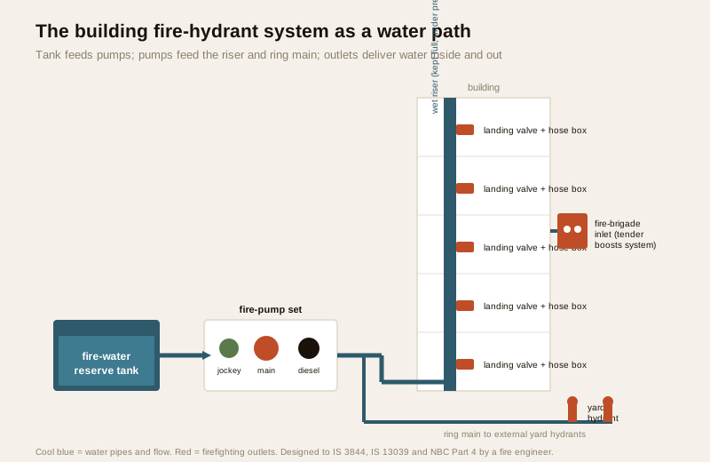
The genius of the design is that the system is always ready. The pipes are kept full of water and held at pressure by the jockey pump, so the moment a firefighter opens any landing valve or yard hydrant, water is there - and the pressure drop from that open valve is what tells the main pump to start and deliver full firefighting flow. The two families of outlet cover the two kinds of firefighting the building needs.
| Part of the system | Where it is | What it does |
|---|---|---|
| Fire-water tank (reserve) | Underground or terrace, dedicated | Holds the ring-fenced water reserve that firefighting draws on - covered in fire-water tanks |
| Fire-pump set (jockey / main / diesel) | Pump room near the tank | Pressurises the network and delivers firefighting flow on demand - covered in fire pumps |
| Wet riser and internal landing valves | Up the stair core, one valve per floor lobby | Delivers water inside the building so hoses reach every floor (IS 3844) |
| External / yard hydrants | Around the building at ground level | Lets the brigade fight the building from outside and reach the perimeter (IS 13039) |
| Fire-service (brigade) inlet | Accessible external wall, near the road | Lets a fire tender pump its own water into the network to boost it |
The internal hydrant - the wet riser and landing valves
Inside a building of any height, water for firefighting is carried up by the wet riser: a large vertical pipe, kept permanently full of water and under pressure, running up through the fire-protected stair core. At each floor, in the stair lobby, the riser feeds a landing valve - a robust outlet valve, almost always painted red, with an instantaneous coupling that a firefighter connects a hose to. Beside it sits a hose box holding a length of fire hose and a branch (the metal nozzle that shapes the water into a jet or spray). A firefighter arriving on a burning floor connects the hose to the landing valve, runs it out toward the fire, opens the valve, and fights the fire with the building's own pressurised water - without having to drag hose up many flights from a tender in the street.
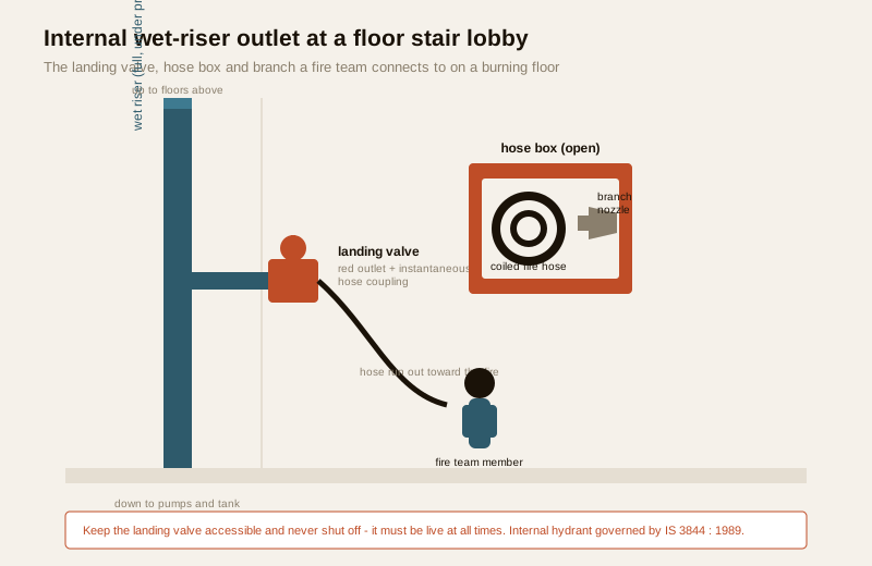
The whole point of the wet riser is height and speed. Whether a building actually needs an internal hydrant or wet riser, and of what size, depends on its occupancy, height and floor area under NBC Part 4 - it is not a single universal threshold, and the determination is the fire engineer's. But the principle is constant: above the reach of a fire tender's own hoses and ladders, the building must carry firefighting water up to the fire itself, and the wet riser with its per-floor landing valves is how it does that. This is exactly why the internal hydrant is load-bearing in high-rise fire safety and in basement fire safety, where firefighters cannot simply reach the fire from the street.
The internal hydrant is defined and governed by IS 3844 : 1989, the code of practice for the installation and maintenance of internal fire hydrants and hose reels on premises - the same code that covers the hose reels that occupants use on a small fire. It is worth being clear on the difference: the hose reel is a first-aid appliance for a trained occupant to hit a small fire early; the landing valve on the wet riser is a firefighting outlet for a trained fire team and the brigade to fight a developed fire. They often sit side by side in the same lobby and are fed by related systems, but they are not the same thing and are not used by the same people.
The external hydrant - yard hydrants around the building
Outside the building, at ground level, the same pressurised water supply rings the site and surfaces at yard hydrants (also called external or ground hydrants): sturdy, freestanding hydrant posts spaced around the building's perimeter, each with one or more outlet valves that the brigade connects hoses to. Yard hydrants let firefighters fight the building from outside - cooling an exposed facade, attacking a fire through a window or opening, protecting a neighbouring structure - and they extend the reach of the system to parts of a large plot that no internal outlet could serve.
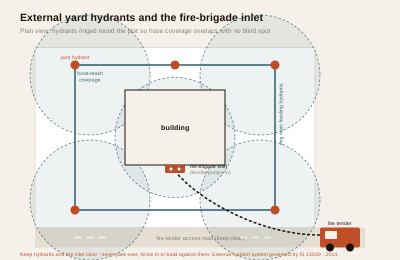
The external hydrant system is governed by IS 13039 : 2014, the code of practice for external hydrant systems - their provision and maintenance. The design idea that matters most to an owner is coverage: yard hydrants must be spaced around the building so that firefighting hoses run out from them can reach every part of the building and the plot, with the coverage circles of adjacent hydrants overlapping so there is no blind spot. Getting that spacing and the ring-main sizing right is a hydraulic-design task for the fire engineer against IS 13039 and NBC Part 4 - what the owner must protect is the coverage once it is built. A yard hydrant that has been built over, fenced in, buried under a landscaping bed or permanently blocked by parked cars is a hole in the ring of protection, no matter how correctly it was designed.
The fire-service inlet - how a tender boosts the system
The third essential outlet is the one that faces the street. The fire-service inlet (also called the brigade inlet or breeching inlet) is a set of hose connections, usually in a boxed enclosure on the external wall near the site entrance, wired into the building's wet riser and hydrant network. Its job is the reverse of a hydrant: instead of taking water out, it lets an arriving fire tender pump water in. If the building's own pumps have failed - the power is out and the diesel pump will not start, or the fire has damaged the pump room - the brigade connects its tender to the inlet and pressurises the whole internal network from its own tank and pumps. It is the system's insurance policy, and it only works if the fire tender can physically reach it and connect to it.
That is where the India reality bites hardest. Fire-service inlets are routinely rendered useless: blocked by a boundary wall or a shop built up against them, buried behind a hoarding, hidden inside a locked cupboard nobody has the key to, or simply unreachable because the tender cannot get its vehicle close enough on a plot with no proper fire-tender access road. An inlet the brigade cannot reach and connect to in the dark, under pressure, is not a fire-safety feature - it is a decoration. Keeping a clear, marked fire-tender access route to the inlet and the yard hydrants is as much a part of the system as the pipework itself.
| The India failure | What has actually happened | Why it is deadly |
|---|---|---|
| Dry system | The riser or ring main has been drained, or the tank is empty | Firefighters open a valve and nothing comes out - the whole network is water in name only |
| Shut landing valve | An isolation or landing valve has been closed and left shut | Water cannot reach that outlet - the floor has no firefighting water when it burns |
| Pump will not start | Jockey pump dead, no auto-start, no diesel backup for the power cut | The network cannot be pressurised - opening a valve gives a trickle, not a firefighting jet |
| Encroached yard hydrant | A hydrant built over, fenced, buried or blocked by parking | A gap in the external coverage - firefighters cannot connect where they need to |
| Unreachable brigade inlet | Inlet walled in, hidden, or no tender access road to it | The brigade cannot boost the system when the building's own pumps have failed |
| Missing hose or branch | Hose box empty, hose rotted, branch stolen | The outlet is live but there is nothing to fight the fire with at the point of use |
None of these are exotic failures. They are the ordinary fate of a system installed to get the Fire NOC and then never watched again - the same neglect that empties fire tanks and kills fire pumps. "Installed" is not "working." A hydrant network is only real if it is full, pressurised, unobstructed and reachable, and proving that is a matter of routine testing and a live maintenance contract, exactly as for every other engineered fire system.
How the hydrant system ties to the rest of the building's fire defence
The hydrant network does not stand alone; it is one delivery layer in a building's water-based fire defence, and it shares its water source and pumps with the others.
- The fire-water tank holds the ring-fenced reserve that the hydrants, and usually the sprinklers, draw on - if the tank is dry, every outlet downstream is dry too.
- The fire pumps pressurise the network - the jockey pump holds standby pressure, the main pump delivers firefighting flow, and the diesel pump is the answer to India's power cuts. A hydrant system with dead pumps is just full pipes.
- The sprinkler system is the automatic first responder that wets the fire the instant it starts, often before anyone arrives; the hydrant is the manual heavy artillery the fire team uses once they do. Many buildings need both, and both are frequently fed from the same tank and pump set.
- The hose reels are the occupant-operated first-aid layer, governed by the same IS 3844 as the internal hydrant and often mounted alongside the landing valve, but for small fires and untrained-but-briefed users - not for fighting a developed fire.
Where you sit in the building shapes which of these matters most. The apartment, office, hotel and hospital fire-safety guides set the hydrant system in each building's overall strategy, and the detection side - the fire-alarm panels and alarm zoning - is what tells everyone the fire has started in the first place, so the fire team knows to bring the hydrant into play. To think through which suppression layers a given building needs, use the fire-suppression system selector; to place the portable and first-aid layer, the fire-extinguisher selector and the home fire-safety scorecard help; and the emergency-preparedness guidance ties the whole response together. For the wider building-systems picture see the commercial-building security guide and the building security systems guide.
What the owner must actually do
The design, hydraulics, sizing, installation and certification of the hydrant system are not the owner's job - they are a licensed fire-protection engineer's and contractor's, delivered against IS 3844, IS 13039 and NBC Part 4 and signed off through the Fire NOC. What is squarely the owner's job is keeping the finished system alive and reachable, and never letting it be quietly defeated.
| Route to the professional | Keep as the owner and manager |
|---|---|
| Hydraulic design and sizing of riser, ring main, valves and outlets | Keep the system full and pressurised - never let it run dry |
| Selecting and sizing the pumps and the fire-water reserve | Never close an isolation or landing valve, and never let one be left shut |
| Installation and commissioning of landing valves, yard hydrants and inlet | Keep every yard hydrant and the brigade inlet clear, marked and reachable |
| Third-party inspection and the Fire NOC certification | Keep the fire-tender access route open - no parking, walls or hoardings |
| Periodic hydraulic testing, flow and pressure verification | Keep hose boxes stocked with sound hose and branches; run it all under an AMC |
Never drain it, never shut it, keep it live and under AMC. The most dangerous thing that can happen to a fire hydrants system is not a design flaw - it is being quietly switched off. A system left drained, a landing valve left shut, a pump left in manual-off with no diesel backup, a yard hydrant built over, a brigade inlet walled in - each of these turns a certified, expensive, life-saving network into pipes full of nothing, and each is invisible until the day the building burns and a firefighter opens a valve to silence. Never drain, isolate or shut off any part of a hydrant system to solve a leak, a noise or a space problem - route the fix to the fire-protection contractor and keep the whole network full, pressurised, unobstructed and reachable under a live maintenance contract, with periodic testing logged. Only a fire-protection engineer designs or modifies it; only the AMC contractor services it; the owner's entire job is to make sure it is never turned off.
Key takeaways
- The fire-hydrant system is the building's high-pressure firefighting water network - the internal wet riser and landing valves that carry water up to every floor (IS 3844), the external yard hydrants that ring the building at ground level (IS 13039), and the fire-service inlet that lets a tender pump water in to boost it, all fed by the fire pumps and the fire-water tank.
- It is the delivery end of a shared system - the same fire-water tank and pump set that feed the hydrants usually feed the sprinklers too; a dry tank or dead pump makes every outlet downstream useless, so read the fire-pumps and fire-water-tanks chapters alongside this one.
- Coverage and reach are the design goals to protect - landing valves in every floor lobby so hoses reach the fire, yard hydrants spaced so their coverage overlaps with no blind spot, and a brigade inlet a fire tender can physically reach; the sizing is the fire engineer's, but keeping the coverage unobstructed is the owner's.
- The deadly India failures are all neglect - dry risers, empty tanks, shut landing valves, pumps that will not start, encroached yard hydrants and unreachable inlets are the ordinary fate of an installed-for-NOC system nobody maintains; "installed" is not "working."
- Never drain, shut or block any part of it - route all design, sizing, installation and modification to a licensed fire-protection engineer and contractor certifying to IS 3844, IS 13039 and NBC Part 4, keep the system full, pressurised and reachable under a live AMC with logged periodic testing, and get everyone out and call 101 or 112 when a serious fire starts.
References
- IS 3844 : 1989 (Reaffirmed 2020), Bureau of Indian Standards - Code of Practice for Installation and Maintenance of Internal Fire Hydrants and Hose Reels on Premises. The core code governing the internal wet riser, landing valves and the associated hose reels within a building. Verify the current edition via the BIS catalogue: https://www.services.bis.gov.in/
- IS 13039 : 2014 (Reaffirmed 2019), Bureau of Indian Standards - External Hydrant Systems: Provision and Maintenance, Code of Practice. The code governing yard hydrants, the external ring main and their spacing and coverage around a building. Verify the current edition via the BIS catalogue: https://www.services.bis.gov.in/
- National Building Code of India, SP 7 : 2026 (the NBC), Part 4 "Fire and Life Safety" - the framework determining whether and what hydrant provision, wet riser, fire-water storage and pumping a building requires by occupancy, height and area; the older SP 7 : 2016 edition is withdrawn but still widely quoted. Verify the current edition via the BIS catalogue: https://www.services.bis.gov.in/
- The relevant State Fire Services Act and Rules and the Model Building Bye-Laws (MoHUA) - these set when a Fire NOC and a certified, maintained hydrant system with fire-tender access are legally required for a given premises, and the periodic testing and maintenance obligations that follow.
This is an educational overview, not legal advice, and not a substitute for a licensed fire-protection engineer or contractor. The hydrant system's hydraulic design, sizing, installation, commissioning, the Fire NOC and any statutory maintenance are qualified professional tasks - engage licensed fire professionals and the State Fire Services, and verify any standard's current status via the BIS catalogue before relying on it.
Export this guide
Related Guides — Deep-dive reading
Fire Water Tanks in India (2026): The Dedicated Reserve That Feeds Everything
The fire-water tank is the reserve that must always be full so the pumps, hydrants and sprinklers have water the moment a fire starts - what it is, how the reserve is ring-fenced, and why a dry tank is the deadliest failure in Indian buildings.
SecurityFire Hose Reels in India (2026): First-Aid Firefighting on Every Floor
The wall-mounted fixed hose reel bridges the gap between a portable extinguisher and the fire brigade - a permanently plumbed water line a trained occupant can use on a small, developing Class A fire while everyone else gets out.
SecuritySprinkler System Maintenance in India (2026): Keeping a Life-Safety System Ready
A fire sprinkler system is a life-safety installation that must work on the one day it is needed — this professional guide covers the scheduled checks, statutory tests and record-keeping that keep a wet, dry or pre-action system live: water supply and pressure, valves in the correct open position, control and alarm valves, sprinkler heads kept clear, and the roles of the competent fire contractor versus the facility manager.
SecurityRelated Tools — Try Free
Fire Suppression System Selector
Sprinklers, hydrants, kitchen-hood, clean-agent gas or water mist? Pick what you are protecting and see the fixed suppression a fire engineer would typically consider — an orientation to a proper NBC Part 4 design, not the design itself.
SuppressionAcoustic Privacy (STC) Visualizer
Indian healthcare acoustic visualizer — compare wall assemblies and noise sources, see received SPL after STC attenuation, and check FGI 2018 / IS 1950 / NABH speech-privacy compliance with live dual-canvas waveform.
Acoustic ToolContract Studio
AI generates professional architecture service agreements with milestones and scope.
ArchitectAI