
Civil Construction of STPs: What Goes Into Building One
Before a single blower runs, an STP is a piece of civil engineering — excavation, watertight RCC tanks, baffle walls, a plant room and drainage, built in a sequence that decides whether the plant ever works. Here is what that construction actually involves.
Ask anyone what an STP is made of and they will describe the machinery — blowers, pumps, diffusers, membranes. But every one of those parts sits inside, or on top of, a structure that was poured months earlier. Before the first blower is switched on, a sewage treatment plant is a piece of civil engineering: a set of watertight concrete tanks in the ground, a room to house the equipment, and a web of pipes and drains connecting them. Get the civil works wrong and no amount of good machinery will save the plant. Get them right and the mechanical fit-out becomes almost routine.
This guide is the civil-works starting point for the build. It walks through what actually goes into constructing an STP — the excavation, the RCC tanks, the baffle walls, the plant room, the pipe galleries and drainage — and the sequence and timelines that tie them together. It sets up the more detailed sub-guides on RCC tank design and waterproofing that follow.
The civil structure of an STP is the one part you can never redo. Pumps can be swapped, blowers upgraded, media re-packed — but a tank that leaks or was built to the wrong size is a permanent, buried mistake. This is why civil works get built first and inspected hardest.
Why the civil works come first
An STP is really two projects stacked on each other: a civil project (the tanks and building) and a mechanical-electrical project (the equipment inside them). The civil works always lead, because everything else is anchored to them — pump foundations, blower plinths, pipe supports and cable trays all fix into concrete that must already be cured and true.
The size and shape of that concrete is not guessed. It comes from the plant's rated capacity in KLD (kilolitres per day) and the hydraulic retention time each stage needs. If you have not fixed those numbers yet, that is the design step that precedes any digging — the STP Capacity Calculator and the guide on how to size an STP turn an occupancy into the tank volumes the civil drawings are built from. The process flow then fixes how many tanks there are and in what order the water moves through them.
The main civil elements
Excavation and foundation
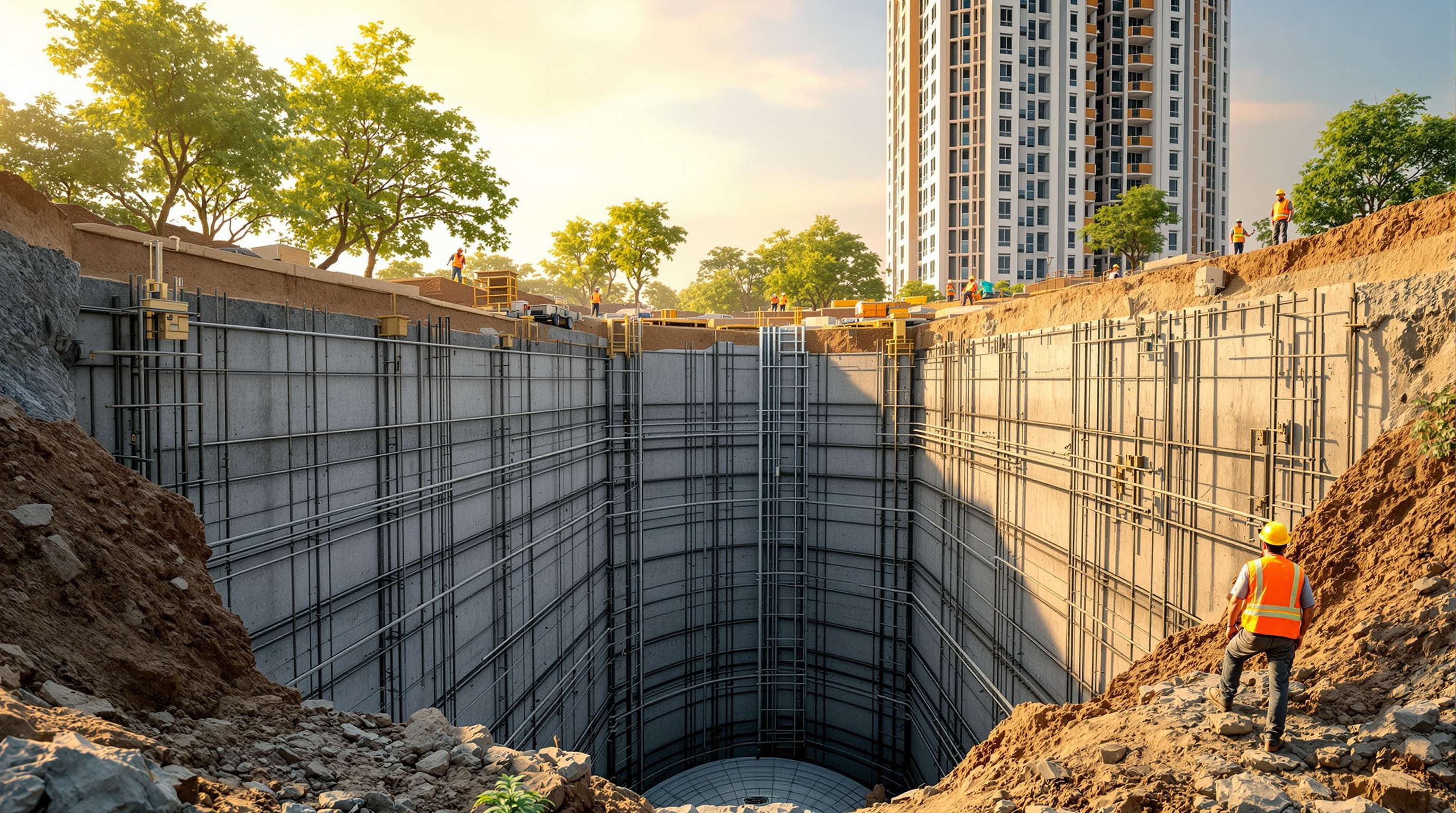
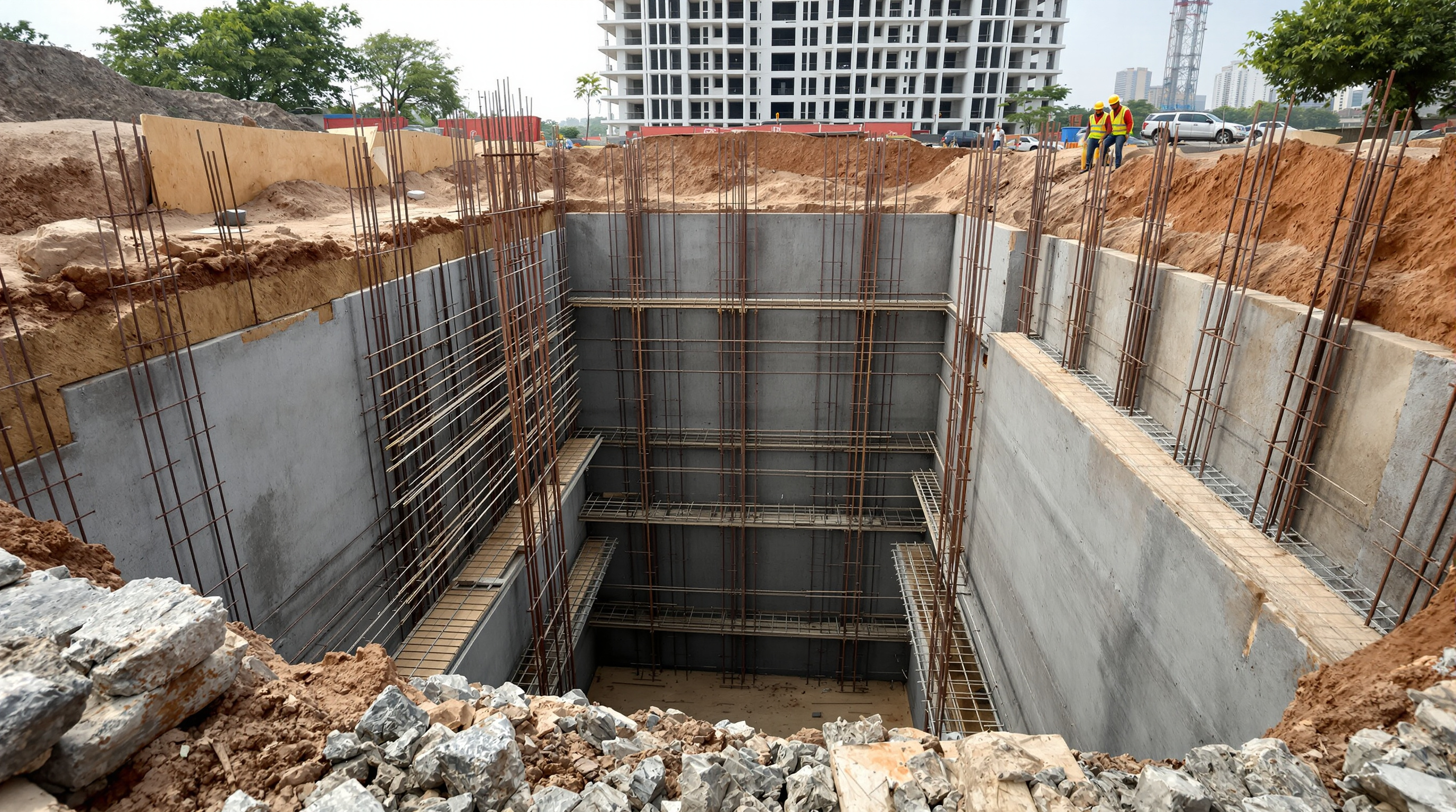
Most STPs in Indian apartment and commercial projects are underground or semi-underground, tucked below a driveway, podium or landscaped setback to save precious plot area. That means the first activity is a deep excavation — often 4 to 6 metres — with all the ground-engineering that comes with it: shoring or sloping the sides, dewatering if the water table is high, and a soil investigation to confirm the bearing capacity.
On the exposed base, a PCC (plain cement concrete) levelling course is laid, followed by the raft foundation — a thick RCC slab that carries the whole plant and, crucially, resists the uplift that groundwater tries to exert on an empty buried tank. In high-water-table sites this flotation check often governs the raft design more than the downward load does.
RCC tanks — the heart of the structure
The treatment tanks themselves are cast in reinforced cement concrete (RCC), typically to a grade of M25 to M30, designed to be water-retaining — a stricter standard than ordinary structural concrete, with tighter crack-width limits so the walls do not weep. A single monolithic tank block is divided by internal walls into the chambers the process needs, usually including:
| Chamber | Job in the process | Related guide |
|---|---|---|
| Collection / equalisation tank | Buffers incoming flow into a steady rate | Equalization tank |
| Anoxic / aeration tank | Holds the biological culture where microbes eat the waste | Aeration tank |
| Settling / clarifier zone | Lets the fattened sludge settle out | Clarifier |
| Treated-water & sludge holding | Stores clean water and collected sludge | — |
The chamber sizes depend on the technology chosen: an MBBR plant packs media into a compact aeration tank, while an MBR system needs a dedicated membrane tank. The civil contractor builds to whatever the process designer has fixed — which is why the two disciplines must agree the general-arrangement drawing before any shuttering goes up.
Baffle walls
Inside the tanks, baffle walls are the quiet workhorses. These are partial internal walls that force the water to follow a longer, deliberate path rather than short-circuiting straight from inlet to outlet. In the aeration zone they help distribute flow and mixing; ahead of a clarifier they slow the water and calm turbulence so solids can settle. They are thin RCC or sometimes masonry, but their position is dictated by the process hydraulics, not by convenience.
Waterproofing
A sewage tank must be watertight in both directions — sewage must not seep out to contaminate the ground and groundwater, and groundwater must not seep in to dilute and flood the plant. Waterproofing is therefore not an afterthought but a designed system: dense, well-compacted concrete first, then construction-joint water-stops, and a protective coating or crystalline treatment on the surfaces. This matters enough to have its own detailed treatment in the waterproofing STP tanks guide.
The plant room
Not everything sits underwater. The plant room (or blower room) is the dry, ventilated structure — often at ground level beside or above the tanks — that houses the blowers, control panel, dosing systems and, in filtration-heavy designs, the pressure sand and activated carbon filters and disinfection skids. It needs its own floor slab, adequate ventilation to clear heat and any gas, sound attenuation for the blowers, and clear working space for the operator and for maintenance access.
Pipe galleries and drainage
Tying it all together is the piping. A well-built STP provides pipe galleries — accessible trenches or channels — so that interconnecting pipework and valves can be reached without breaking concrete later. Puddle flanges are cast into the walls at every point a pipe passes through, so those penetrations stay watertight. Finally the structure needs its own drainage: floor drains, an overflow route, and a sump with a dewatering pump so that spills, wash-down water and any leakage are collected and returned into the process rather than pooling in the plant room.
The typical construction sequence
Civil works follow a logical order, each step gating the next:
- Design freeze — process sizing, GA drawings and structural design signed off.
- Excavation and dewatering — dig to level, shore the sides, control groundwater.
- PCC and raft — levelling course, then the base slab with uplift checks.
- Walls and baffles — shuttering, reinforcement, then casting the tank walls and internal walls.
- Curing and waterproofing — proper water curing, then the waterproofing system.
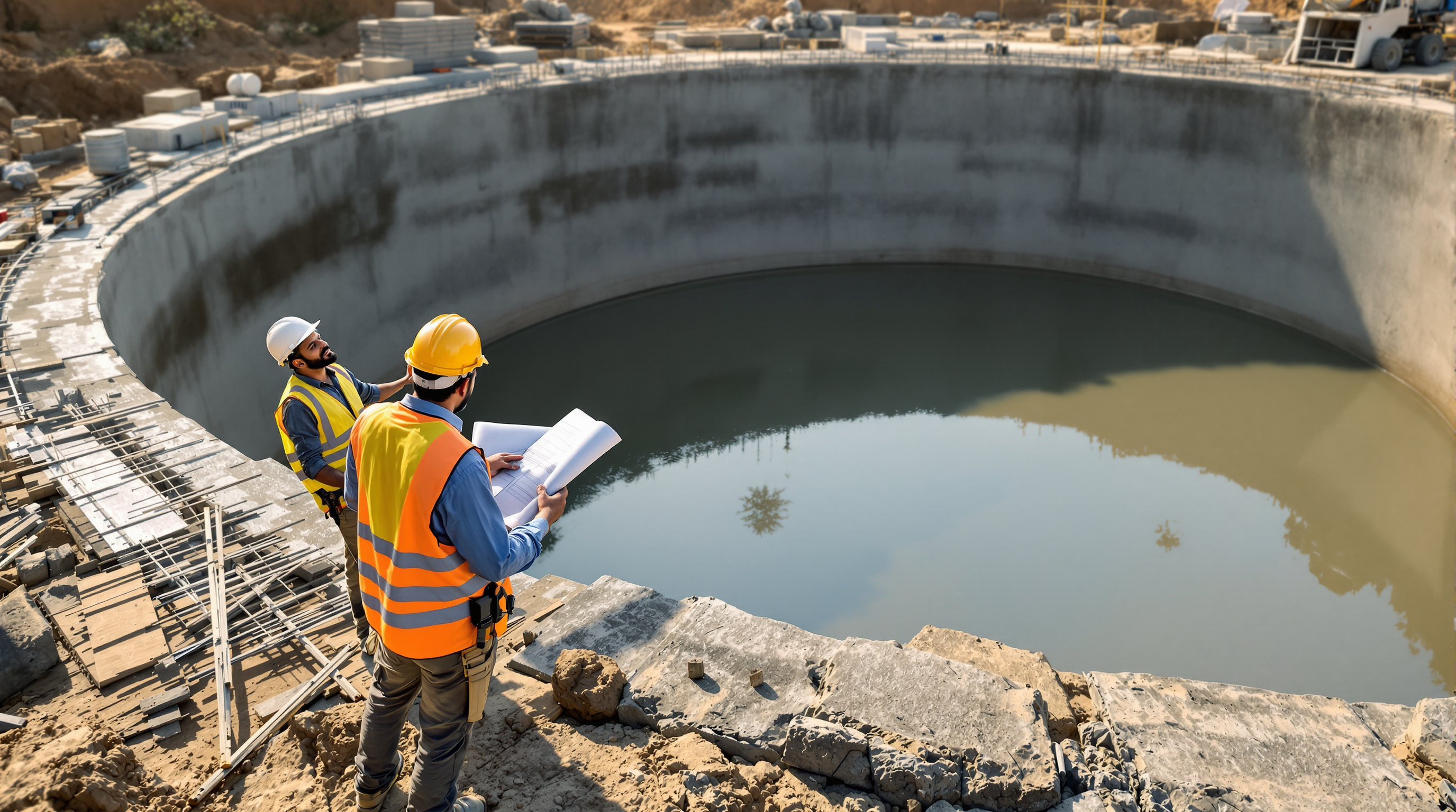
- Water-tightness test — fill the tanks and hold; confirm no drop before proceeding.
- Plant room and backfill — build the superstructure, backfill around the tanks in layers.
- Handover to mechanical — the cured, tested structure is released for mechanical installation.
That water-tightness test is the make-or-break checkpoint — never let the mechanical fit-out start on an untested tank.
Typical timelines
For a mid-sized building STP — say a few hundred KLD — the civil works alone usually run 6 to 12 weeks, and often longer where deep excavation, a high water table or a congested basement slows access. The pattern is consistent: excavation and the raft are quick; wall casting plus the mandatory curing time is the long pole; and the water-tightness test adds a firm week that cannot be compressed. Only once civil is signed off does the plant move on to mechanical and electrical installation, then commissioning.
The bottom line
The civil construction of STPs is the unglamorous half of the project that quietly decides the other half's fate. Excavation, a raft that resists uplift, watertight M25–M30 RCC tanks divided by process-driven baffle walls, a properly ventilated plant room, accessible pipe galleries and honest drainage — built in the right sequence and proven with a water-tightness test — are what a good STP is actually made of. Everything the plant does later depends on getting this concrete right the first time.
From here, dig into the detail with the RCC tank design and waterproofing guides, or step back to the full Sewage Treatment Plants library to see where civil works sits in the whole build. To pressure-test your own project's numbers before drawings begin, the STP Cost Estimator and STP Capacity Calculator are the two tools to start with.
Export this guide
Related Guides — Deep-dive reading
The Sewage Treatment Process Flow, Explained: Every Stage From Inlet to Reuse
Follow a drop of sewage through a typical STP — inlet, screening, aeration, clarifier, filtration, disinfection and reuse — as one connected flow, with a block diagram and a unit-by-unit table, in plain language.
Sewage Treatment PlantsMechanical Installation of STP Equipment: Blowers, Pumps, Diffusers & Pipework Done Right
How the blowers, pumps, diffuser grids, media, screens, tube settlers and pipework of a sewage treatment plant are actually set, aligned, anchored and supported on site — and the pre-commissioning mechanical checks that decide whether the plant runs quietly for years or rattles itself apart in months.
Sewage Treatment PlantsSTP Layout Planning: Arranging Tanks, Plant Room and Pipe Runs the Right Way
How to lay out an STP so sewage flows downhill by gravity, every tank can be reached for maintenance, and the plant can grow later — compared against real compact and linear arrangements used in Indian buildings.
Sewage Treatment PlantsRelated Tools — Try Free
Rainwater Tank Sizer
How big should your rainwater tank be? Computes annual harvest, recommended tank capacity in litres, water-bill savings, and payback — for 10 Indian cities.
RWH CalculatorApartment STP Planner
Plan an apartment complex sewage treatment plant from flats and occupancy — get population load, sewage flow, recommended STP capacity in KLD, treatment technology and approximate space.
PlannerPool Volume Calculator
Water volume in litres, US gallons and cubic metres, by pool shape and depth.
Pool Calculator