
RCC Tank Design for STPs: Liquid-Retaining Structures Done Right
How the reinforced-concrete tanks that hold your sewage treatment plant are actually designed — wall thickness, crack control to IS 3370, freeboard, partitioning for treatment stages, and the buoyancy checks that keep underground tanks from floating.
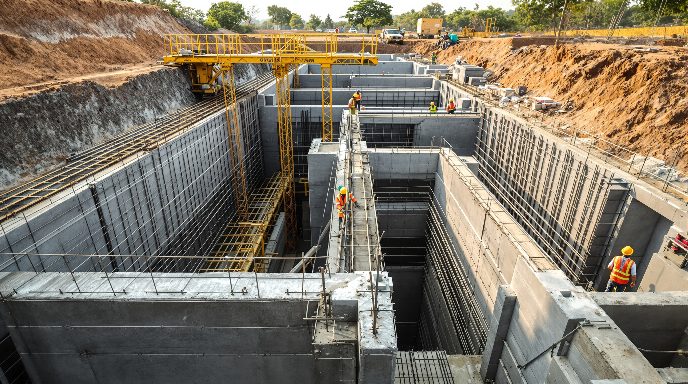
Strip away the blowers, pumps and diffusers and an STP is, fundamentally, a set of watertight concrete boxes. The equalisation tank, the aeration tank, the clarifier, the sludge holding tank, the treated-water sump — every one is a reinforced-concrete (RCC) vessel that must hold sewage for decades without leaking, cracking or, if it is buried, floating out of the ground. The mechanical equipment gets replaced every ten or fifteen years. The tanks are forever. Getting their design right is the difference between a plant that quietly works and one that seeps, corrodes and undermines the building next to it.
This guide walks through how those tanks are actually designed — as liquid-retaining structures, a distinct and stricter branch of RCC design governed directionally in India by IS 3370. It is written for the civil engineer detailing the tank and for the informed owner who wants to know what they are paying for. It sits alongside the broader civil construction of STPs guide, which covers excavation, formwork and pouring on site.
A liquid-retaining structure is not designed to "not collapse." It is designed to not crack wide enough to leak. That single shift — from strength to serviceability — is what makes STP tank design its own discipline.
Why STP tanks are not ordinary RCC

An ordinary RCC beam or column is allowed to crack. Steel is assumed to carry tension, concrete is assumed to have already cracked in the tension zone, and design is governed by ultimate strength. A tank cannot work that way. If the tension face cracks, sewage weeps through, reinforcement corrodes, and the structure fails long before its strength is ever tested.
So liquid-retaining design flips the priority to serviceability — crack width first, strength second. IS 3370 limits calculated surface crack widths to about 0.2 mm for severe exposure (a sewage-holding face qualifies), and the whole calculation is arranged to keep the concrete in tension well below the point where a leaking crack can form. In practice this drives three decisions: richer concrete, more steel at closer spacing, and thicker sections than a strength calculation alone would ever ask for.
Typical material choices for STP tanks in India:
| Item | Typical specification | Reason |
|---|---|---|
| Concrete grade | M30 (minimum), often M35 for sewage contact | Denser, lower-permeability matrix resists seepage |
| Cement content | Rich mix, low water-cement ratio (~0.45) | Watertightness comes from a dense paste, not just steel |
| Reinforcement | Fe500, closely spaced small-diameter bars | Many thin bars control cracks better than few thick ones |
| Cover to steel | 40–50 mm on liquid faces | Protects reinforcement from aggressive sewage |
| Crack width limit | ~0.2 mm (severe exposure) | The governing serviceability criterion |
Note the reinforcement logic: to control cracking you want distributed steel. Two 12 mm bars carry the same force as one 16 mm bar, but spread the crack-controlling grip over more of the surface, so a tank is deliberately detailed with smaller bars at tighter spacing than a strength check would suggest.
Wall thickness and how it is set
Wall thickness in a tank is rarely governed by bending strength. It is governed by three softer constraints: keeping concrete tension low enough to avoid cracks, giving reinforcement its 40–50 mm cover on both faces plus a working core, and staying practically buildable. As a rough field rule, STP tank walls land around 200–300 mm for shallow tanks and 300–450 mm or more for deep aeration and equalisation tanks holding several metres of liquid.
The wall is analysed for the load case that matters most — usually tank full, no soil support outside (the test and early-service condition) for internal pressure, and for buried tanks the reverse case of tank empty with full earth and groundwater pressure pushing in. The base slab is designed for the upward soil reaction and, critically, for uplift. Walls spanning both vertically (cantilevering off the base) and horizontally (spanning between cross-walls) are designed for whichever action dominates given the tank's proportions.
Because the deeper a tank goes the thicker its walls and base must get, tank depth is an economic decision, not just a hydraulic one. That trade-off starts from the plant's flow, which the STP Capacity Calculator turns into a design KLD figure, and feeds into the volumes you set in how to size an STP.
Crack control: the real design driver
Cracks in a tank come from two sources, and both must be handled.
- Flexural cracking — from the water and earth pressure bending the walls. Controlled by limiting steel stress and spacing bars closely.
- Thermal and shrinkage cracking — from the heat of hydration as a large concrete pour cures, and from drying shrinkage afterwards. This is often the bigger threat in long tank walls, and it is why IS 3370 mandates generous minimum surface reinforcement in both directions regardless of what the load calculation asks for.
Practical measures that keep tanks watertight:
- Movement and construction joints with PVC or hydrophilic water-stops cast into every joint plane.
- Pour sizing and sequencing to limit the length of any single continuous pour, reducing shrinkage restraint.
- Kicker-less or well-detailed construction joints between base and wall, the classic leak line.
- Curing discipline — a tank cured for a full 14 days behaves very differently from one left to dry in the sun.
Crack control is where civil design hands over to protection. Even a well-detailed tank is given a chemical or membrane barrier on its wetted faces; that is the subject of the waterproofing STP tanks guide, and the two disciplines must be designed together, not bolted on afterwards.
Freeboard and partitioning for the process
Freeboard is the deliberate air gap between the top water level and the top of the wall — typically 300–500 mm. It absorbs surges, the froth and foam an aeration tank generates, and a margin against overtopping. Skimp on it and an aeration tank spits foam over its walls; overdo it and you have paid for concrete that never touches water.
A single STP is almost never one tank. It is a partitioned block where common RCC cross-walls divide the structure into the treatment stages in sequence — equalisation, anoxic/aeration, clarifier, sludge holding and treated-water sump often share walls in one monolithic raft. This is efficient (shared walls, one excavation, one base slab) but it makes the internal baffle and partition walls structural actors in their own right:
- A partition with liquid on one side only (one compartment full, the neighbour drained for cleaning) sees full hydrostatic pressure and must be designed for it — this "differential" case often governs the internal walls.
- Weir and baffle walls in the clarifier and equalisation tank set hydraulic levels and must be cast to tight level tolerances.
- Openings for pipes and channels between compartments are detailing hot-spots — every penetration is a potential leak and gets a puddle flange or sleeve cast in, never core-drilled later.
Compact technologies such as MBBR and MBR shrink these compartments but raise the detailing stakes — media retention screens and membrane cassettes need precise, level, well-anchored fixings cast into the RCC.
Buoyancy and uplift: keeping buried tanks down
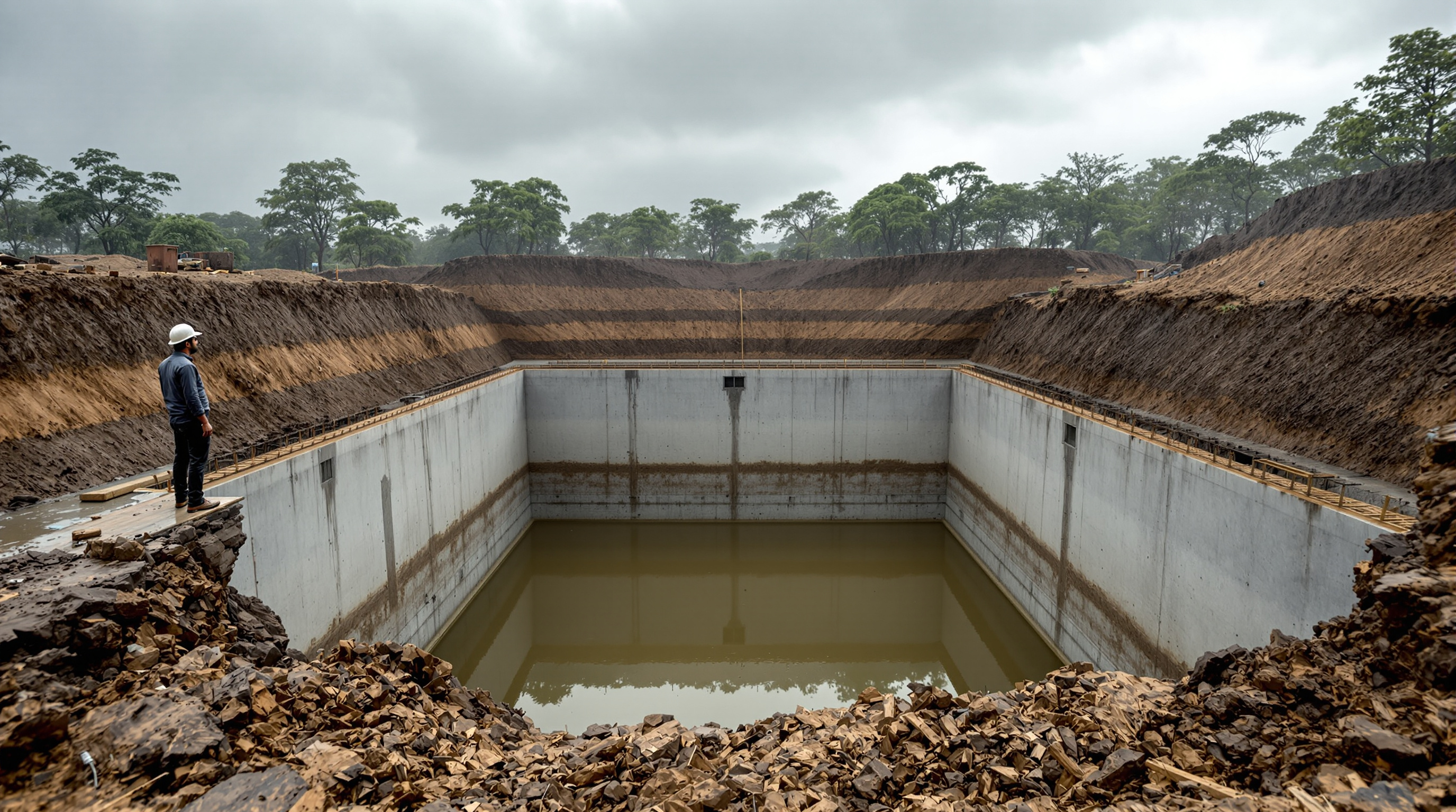
The most under-respected calculation in STP civil design is flotation. An underground tank is a hollow box in the ground. When it is empty — during construction, or when it is drained for maintenance — and the surrounding soil is saturated, the groundwater tries to push the whole empty box upward like a boat. If the upward force of displaced water exceeds the tank's self-weight, the tank literally rises, cracks its pipe connections and heaves the ground.
The check is a simple balance, taken with the worst case of empty tank + high water table:
- Uplift force = weight of water displaced by the tank's full submerged volume.
- Resisting force = self-weight of the concrete + weight of soil bearing on any projecting base "heel" + friction on the walls, usually with a factor of safety of about 1.2.
When the numbers do not balance — common for large, shallow, high-water-table tanks — engineers add resistance rather than hope:
- Thicken the base slab to add dead weight (the simplest fix).
- Extend the base slab as a projecting toe/heel so the weight of soil above it holds the tank down.
- Anchor piles or tension anchors into stable strata below for severe cases.
- Provide a controlled release / pressure-relief so groundwater cannot build up under the base — used with care.
Ignoring this check is how brand-new empty STP tanks end up floating out of monsoon-flooded excavations. Where the water table is high, it is one of the first calculations, not the last.
The bottom line
RCC tank design for an STP is liquid-retaining design: crack control before strength, watertightness engineered into the concrete and its joints, freeboard sized to the process, partitions designed for the one-side-full case, and buoyancy checked for the empty tank in wet ground. Get these five right and the civil shell will outlast three generations of pumps and blowers.
From here, follow the build sequence through civil construction of STPs and waterproofing STP tanks, or step back to the Sewage Treatment Plants guide library for the full picture — from process flow to reusing the treated water the tanks help produce.
Export this guide
Related Guides — Deep-dive reading
Waterproofing STP Tanks: Watertight Both Ways, Joints, Coatings and the Water-Fill Test
Why an STP tank has to hold water in and keep groundwater out, the waterproofing systems that actually work — crystalline, coatings and water bars at construction joints — and how the water-fill test proves the tank is sound before you ever commission it.
Sewage Treatment PlantsCivil Construction of STPs: What Goes Into Building One
Before a single blower runs, an STP is a piece of civil engineering — excavation, watertight RCC tanks, baffle walls, a plant room and drainage, built in a sequence that decides whether the plant ever works. Here is what that construction actually involves.
Sewage Treatment PlantsHow to Size an STP: A Step-by-Step Method (With Worked Example)
The complete sizing methodology for a domestic sewage treatment plant — from headcount and LPCD to sewage generation, peak flow and tank-by-tank volumes — worked end to end with an Indian apartment example.
Sewage Treatment PlantsRelated Tools — Try Free
Acoustic Privacy (STC) Visualizer
Indian healthcare acoustic visualizer — compare wall assemblies and noise sources, see received SPL after STC attenuation, and check FGI 2018 / IS 1950 / NABH speech-privacy compliance with live dual-canvas waveform.
Acoustic ToolRainwater Tank Sizer
How big should your rainwater tank be? Computes annual harvest, recommended tank capacity in litres, water-bill savings, and payback — for 10 Indian cities.
RWH CalculatorMonsoon-Readiness Checklist
Pre-rain home audit across 9 categories — terrace, drains, waterproofing, electrical, HVAC, pest, vehicles, documents.
Seasonal Audit