
Electrical Installation for STPs: Panels, Cabling, Earthing and Safety
How the electrical works of a sewage treatment plant are actually built — the MCC panel, motor cabling, earthing, standby power and the safety rules that keep a wet, humid plant room from becoming a hazard.
An STP is often described in biological terms — microbes, oxygen, sludge — but strip away the biology and what you have is a room full of motors. Pumps that lift sewage, blowers that push air, dosing units, filter feed pumps, a bridge scraper turning slowly in the clarifier. Not one of them moves without electricity. The electrical installation of an STP is the nervous system that brings the whole plant to life, and it is also, in a damp basement full of water and moving machinery, the part most capable of hurting someone. Get it right and the plant simply runs. Get it wrong and you have tripping motors, burnt-out windings, nuisance shutdowns, and a genuine shock hazard.
This guide walks through how the electrical works of an STP are actually built and commissioned — the panel, the cables, the motor connections, earthing, standby power, and the safety discipline a wet plant room demands. It sits alongside the mechanical installation and instrumentation installation guides, because in practice the three trades are stitched together on site.
In an STP the electrical panel is not an accessory to the plant — it is the plant's control room. Every process decision, from how much air the tank gets to when a pump cuts out on high level, is executed here.
Start with the load list
Before a single cable is pulled, the electrical design begins with a load list — an honest tally of every motor and its rating. This is where the electrical engineer and the process engineer must sit together, because the connected load flows directly from the equipment the sizing exercise fixed.
A typical package STP load list looks something like this:
| Equipment | Typical rating | Duty |
|---|---|---|
| Raw sewage / submersible pumps | 1–5 HP each | Duty + standby |
| Air blowers (aeration) | 3–15 HP each | Duty + standby, often the biggest load |
| Filter feed pump | 2–5 HP | Intermittent |
| Sludge / recirculation pump | 1–3 HP | Intermittent |
| Dosing pumps (chlorine, etc.) | Fractional HP | Intermittent |
| Bridge / scraper drive | Fractional–1 HP | Continuous, slow |
From this you arrive at the connected load (everything added up) and, more usefully, the maximum demand — because not every motor runs at once. The standby pump sits idle while its duty twin works; the filter feed pump runs only during backwash cycles. Applying a sensible diversity factor gives the demand the incoming supply and DG must actually serve. The blowers almost always dominate: aeration runs close to 24×7, so it is the single largest and most continuous consumer in the plant.
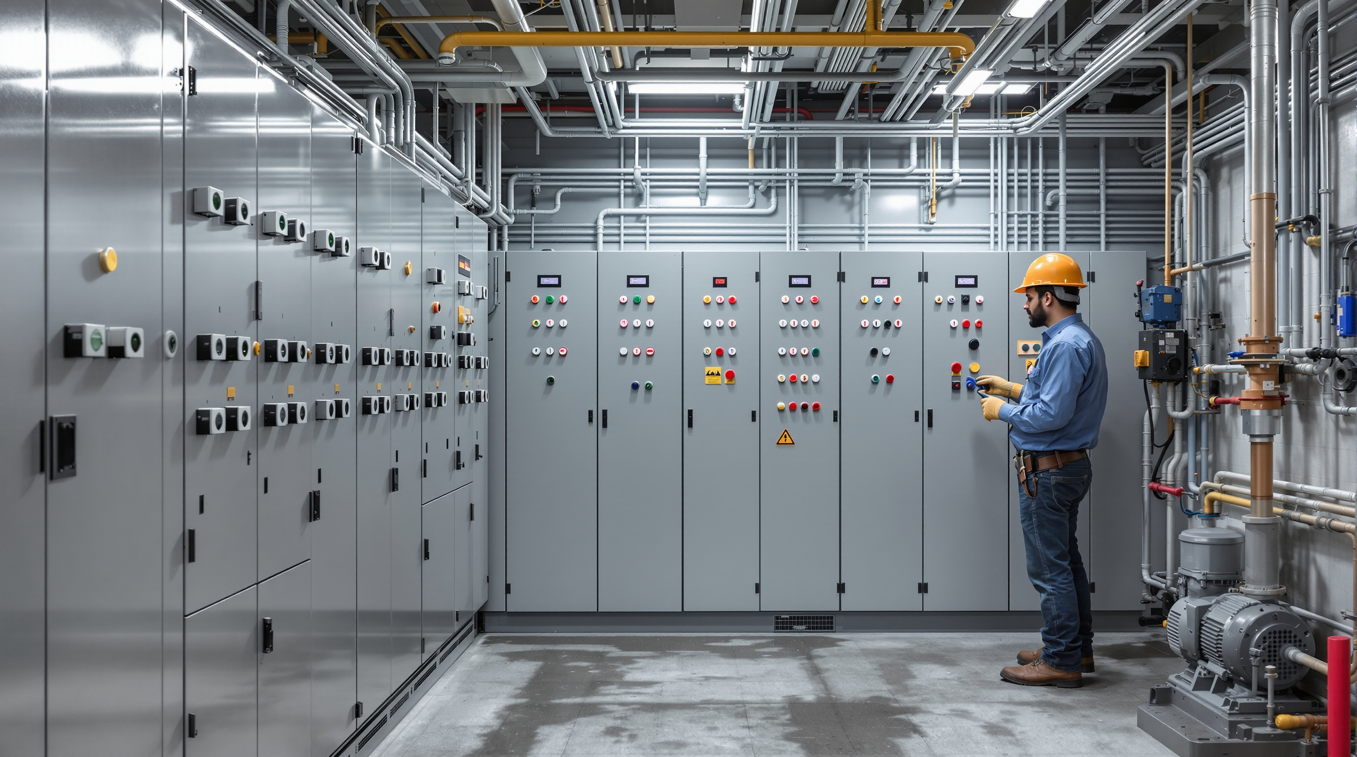
The MCC panel — the heart of the installation
The centrepiece is the Motor Control Centre (MCC), sometimes called the STP control panel. This is the metal cabinet from which every motor is switched, protected and monitored. A well-built MCC for an Indian STP will typically include:
- An incomer — the main switch (MCB/MCCB) bringing in power, with an ammeter and voltmeter.
- A feeder for each motor — its own MCCB or motor-protection circuit breaker, a contactor, and an overload relay set to the motor's full-load current so a jammed or overloaded pump trips before it burns.
- Star-delta starters for larger motors (typically above ~7.5 HP) to soften the inrush current at startup, or VFDs (variable frequency drives) on blowers where you want to modulate air rather than run flat out.
- Auto/Manual selector switches so each motor can run on level-controlled automatic logic or be forced by hand during testing.
- Duty/standby changeover logic so pumps alternate and a failed duty pump hands over to its standby automatically.
- Indication lamps (run / trip / power) and, increasingly, a PLC or level-controller interface.
Two details matter enormously in an STP and are routinely skimped. First, the enclosure protection rating: a plant-room panel should be at least IP54, and IP55 is safer given the humidity and occasional hose-down. Second, panel location — it must sit in the driest, best-ventilated corner of the plant room, clear of splashing tanks, ideally on a raised plinth so a floor flood never reaches its base.
Cabling: sizing, routing and glanding
Cables carry the power from the MCC to the motors, and in a wet basement they take punishment. Three decisions define good cabling.
Sizing. Each cable is sized for the motor's full-load current plus headroom for voltage drop over the run and for the ambient derating of a hot, enclosed plant room. Undersized cable runs warm, drops voltage, and starves the motor — a classic cause of motors that hum but will not start.
Type and armour. Underground and floor-level runs use XLPE-insulated armoured cable (the steel armour resists rodents and mechanical damage). Submersible pump cables must be the correct submersible-rated flexible type, continuous with no joints below water.
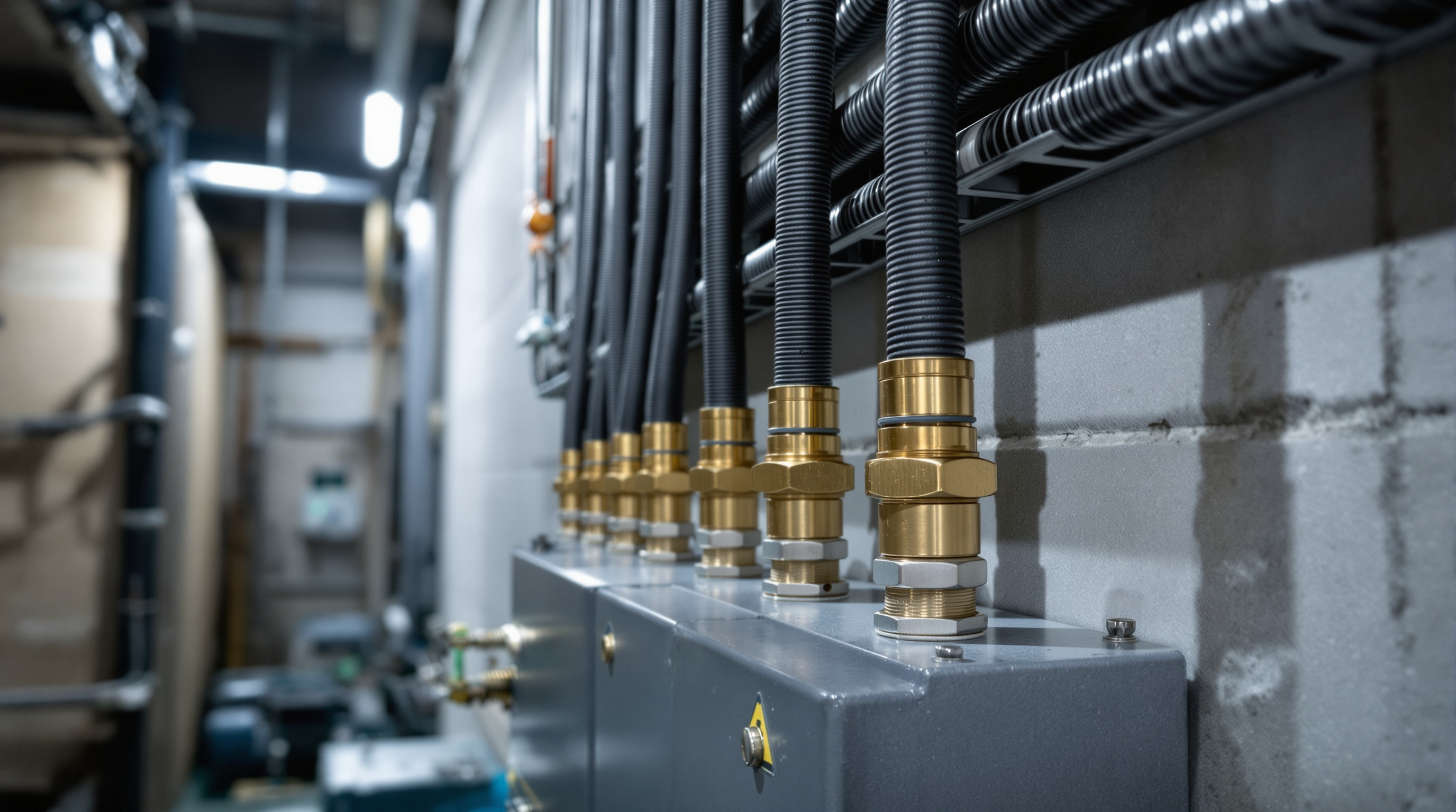
Routing. Cables run on GI cable trays or in conduits, dressed neatly, with power and signal cables kept apart (more on that below). Every cable is glanded properly where it enters a panel or a motor terminal box — a correct double-compression gland with the armour clamped is what keeps water and vermin out and maintains earth continuity. Loose, ungланded, taped-up entries are the single most common defect a commissioning engineer finds.
Motor connections and earthing
At the motor end, the cable lands in the terminal box, wired in star or delta to match the starter, with lugs crimped — never twisted — onto the terminals. The terminal box lid must seal; in the splash zone of an aeration tank a poorly sealed box invites moisture straight onto live terminals.
Earthing is not optional and not an afterthought. In a plant where people stand on wet floors and touch metal machinery, earthing is what stands between a winding fault and a fatal shock. Good practice means:
- Every motor body and every panel is connected to earth by two separate earth conductors (double earthing), following the spirit of Indian wiring practice.
- A dedicated earth pit system, tested for low earth resistance (aim well under the commonly cited few-ohm range), with earth strips run continuously back to the panel.
- RCDs / ELCBs (earth-leakage protection) on circuits so an insulation failure trips the supply in milliseconds rather than energising the machine casing.
- Bonding of all exposed metalwork — tank railings, ladders, cable trays — so nothing can float at a dangerous voltage.
Damp, chlorine-laden air corrodes connections over time, so earth continuity is something to re-check at every service, not just at handover.
Standby power: the DG set
An STP cannot simply stop when the grid fails. Sewage keeps arriving whether or not there is power, and prolonged aeration loss kills the biological culture the plant depends on. So an STP is almost always connected to the building's diesel generator (DG) backup through an AMF (Auto Mains Failure) panel, which starts the DG and transfers the load within seconds of a power cut.
The design question is which loads to back up. Backing up the entire connected load is expensive; the pragmatic answer is to prioritise the essential loads — the raw sewage pumps (so the sump does not overflow) and at least one aeration blower (so the microbes keep breathing). Dosing, filtration and non-critical pumps can wait for mains to return. This priority split should be agreed early, because it sizes the DG allocation the STP is given and feeds straight into the running-cost picture that the cost estimator captures.
Coordinating with instrumentation
Power and control are two conversations happening on the same cables tray, and they must be kept civil. The MCC does not decide anything on its own — it acts on signals from the instruments: level switches in the sump and tanks that start and stop pumps, DO and pH sensors that trim the blowers and dosing, flow meters that log throughput. The pumps and instrumentation guide covers those devices; the electrical job is to wire them correctly.
The golden rule: keep signal cables away from power cables. The 4–20 mA and low-voltage sensor signals that instruments produce are easily corrupted by the electromagnetic noise a running motor cable throws off. Route them on a separate tray or in a separate conduit, cross power cables at right angles rather than running parallel, and use shielded cable earthed at one end. A plant that "trips randomly" or shows drifting sensor readings very often has nothing wrong with its process — it has signal cables zip-tied to power cables.
Safety discipline in a wet plant room
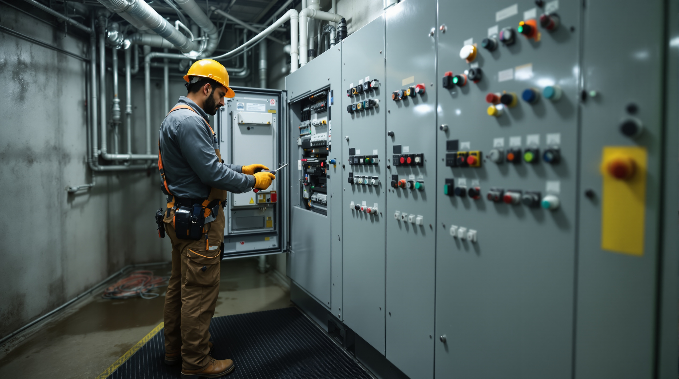
Everything above converges on one point: a basement STP is one of the more hazardous electrical environments in a building — standing water, high humidity, rotating machinery, chlorine gas, and confined space all in one room. Non-negotiables:
- Lock-out / tag-out before working on any motor — isolate at the panel and lock it, so no one starts a pump while a hand is in it.
- IP-rated fittings and sealed junction boxes throughout; no domestic-grade switches in the splash zone.
- Insulated tools, rubber mats at the panel, and gloves for wet-area work.
- Proper ventilation and lighting — a dim, unventilated plant room is where mistakes happen.
- Earth-leakage protection tested and proven to trip, not just installed.
The bottom line
The electrical installation is what turns a set of tanks and machines into a working STP. Done well it is invisible — the plant simply runs, alternates its pumps, rides through power cuts and keeps the microbes fed. Done badly it is the source of every nuisance trip, burnt motor and safety scare the operator will curse for years. Treat the MCC, the cabling, the earthing and the DG changeover with the same seriousness as the biology, keep power and signal apart, and respect the wet room you are working in.
From here, continue to the instrumentation installation guide to see how the sensors that drive this panel are set up, then on to the commissioning procedure where the whole plant is energised and proven. The full Sewage Treatment Plants guide library ties the electrical, civil and mechanical trades together.
Export this guide
Related Guides — Deep-dive reading
Mechanical Installation of STP Equipment: Blowers, Pumps, Diffusers & Pipework Done Right
How the blowers, pumps, diffuser grids, media, screens, tube settlers and pipework of a sewage treatment plant are actually set, aligned, anchored and supported on site — and the pre-commissioning mechanical checks that decide whether the plant runs quietly for years or rattles itself apart in months.
Sewage Treatment PlantsCollection Tank (Raw Sewage Sump) in an STP: The First Sump Explained
The raw sewage sump is where a building's drains empty and treatment begins. Here is what the collection tank does, how its float switches and submersible transfer pumps work, and why it is not the same thing as the equalisation tank.
Sewage Treatment PlantsAir Blowers & Diffusers in an STP: How Aeration Actually Works
The blowers that push air and the diffusers that turn it into bubbles are the lungs of your sewage treatment plant. Here is how they work, how they are sized, and why they decide most of your electricity bill.
Sewage Treatment PlantsRelated Tools — Try Free
Electrical Safety & Load Audit
Home electrical audit — 10 categories, 65+ checkpoints across earthing, RCCB, MCB, wiring, switchboards, appliance circuits, DG/inverter backup.
Safety AuditFalse Ceiling Cost Estimator
Live ₹/sqft across 8 ceiling types — POP, gypsum, designer, metal, PVC, wooden — with cove and spot lighting for 20 Indian cities.
Cost CalculatorLift Power Requirement Calculator
Connected load, single vs three phase, MCB and cable guidance for a home lift.
Lift Calculator