
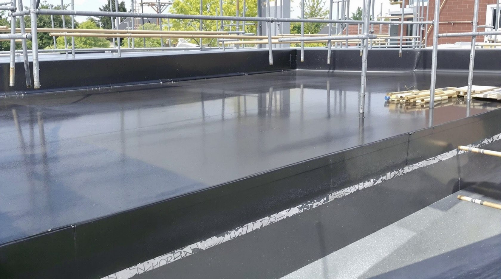
Roof Detailing That Doesn't Leak: The Critical Junctions
Roofs almost never fail in the open field. They fail at junctions. A professional's guide to the details that make or break a roof in India: parapet upstands and terminations, penetrations, outlets, expansion joints, abutment flashings, box gutters and valleys, falls, and the tile-roof and metal-roof details that keep water out.
Walk any leaking roof in India with an experienced waterproofing applicator and watch where they go. Not to the middle. They go straight to the edges — the parapet corner, the pipe that pokes through, the drain mouth, the joint where the terrace meets a taller wall. Because roofs almost never fail in the open field. The membrane in the middle has one simple job and usually does it. Roofs fail at junctions: the places where the flat surface stops and has to turn, terminate, wrap something, or move. Get the junctions right and an ordinary roof lasts decades. Get them wrong and the best membrane money can buy will still let water in within a monsoon or two.
This is the detailing deep-dive of the Roofing Knowledge Hub and a companion to The Ultimate Guide to Roofing Systems. It is written for the people who draw, specify, build and inspect these details — the architect, the structural engineer, the waterproofing specialist, the site engineer, the PMC. It sets out, junction by junction, what a good detail looks like and how it typically fails: waterproofing upstands and terminations, penetrations and collars, outlets and drain mouths, expansion and movement joints, roof-to-wall and abutment flashings, box gutters and valleys, the fall that everything depends on, and the ridge-hip-valley-eave-verge details of tile roofs plus the lap-and-fastener discipline of metal roofs. The cost of getting a detail wrong is never the detail: it is the ceiling below it, the re-work, the disputes, and the reputation of everyone whose name was on the drawing.
Scope & safety. This guide is a best-practice detailing aid, not a substitute for a site-specific design or statutory certification. Actual upstand heights, falls, joint widths, membrane systems and flashing gauges must be set by the project designer and the waterproofing system's manufacturer datasheet, and verified against the current standards and the local authority. The licensed structural engineer remains responsible for structural design and certification; the licensed contractor for execution and safety at height. Dimensions here are common rules of thumb to sanity-check a drawing, not values to build to blind. Confirm any Indian Standard's current status via the BIS catalogue.
Why junctions, not the field, decide the roof
A flat membrane laid over an open field is doing the easiest work it will ever do: lie flat and shed water that runs away. The trouble starts wherever that plane is interrupted. Three things happen at a junction, and each is a way in:
1. The membrane has to change direction. A sharp 90-degree internal corner (slab-to-parapet, slab-to-kerb) is where a membrane is stretched thinnest and stressed hardest; it cracks or debonds there first.
2. The membrane has to terminate. Every sheet has an edge that must be locked down and sealed so water cannot creep behind it. A termination stuck on a flat vertical face with no mechanical anchorage is a countdown to failure.
3. The membrane has to wrap or accommodate movement. Pipes, posts and joints all move differently from the slab; the detail has to seal them and let them move without tearing.
Everything below is about turning those three moments into deliberate, repeatable details. The single map worth carrying in your head is this: the field is safe, the junctions are not.
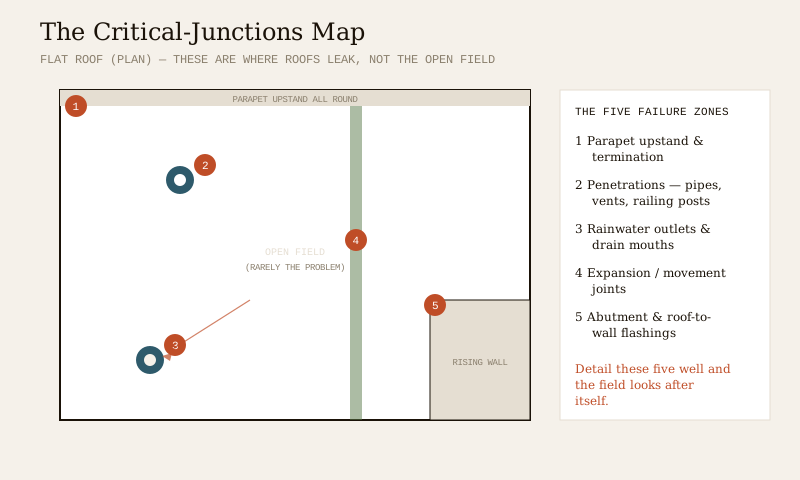
The parapet upstand and termination
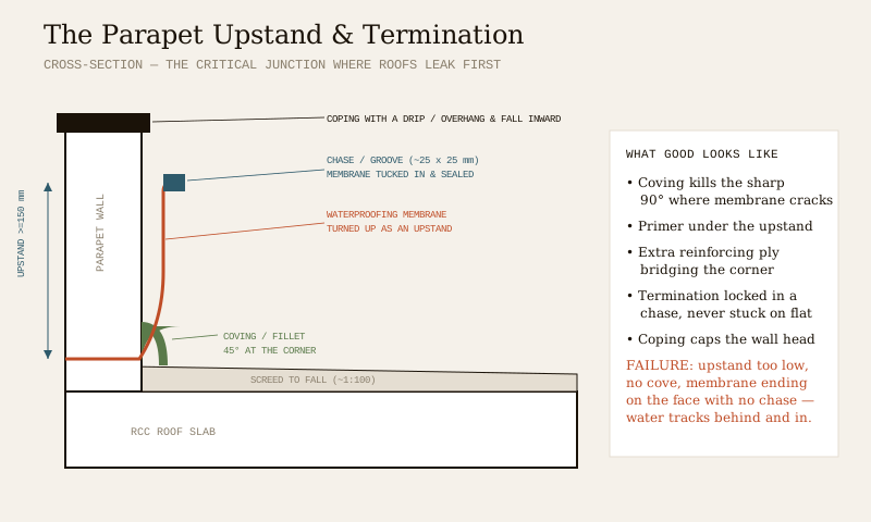
This is the classic critical junction and the one most often botched. Where the roof meets the parapet, the waterproofing must not simply stop at floor level — it must turn up the wall as an upstand and terminate securely at the top so that wind-driven rain, splashing and any temporary ponding cannot get behind it.
Three things define a good parapet detail, shown in the cross-section below:
- A coving (fillet) at the corner. A 45-degree mortar or system fillet at the slab-to-parapet internal corner removes the sharp right angle so the membrane sweeps up in a gentle curve instead of being forced around a knife-edge. Without it, that corner is the first thing to crack.
- A generous upstand height. The membrane should run up the wall well above the finished roof level so it is never overtopped. A common rule of thumb is at least 150 mm above the finished surface, more where ponding, heavy exposure or a shallow fall is possible — but confirm the figure against the waterproofing system datasheet and the designer.
- A locked-in termination. The top edge should be tucked into a chase (groove) cut in the wall (roughly 25 mm by 25 mm), sealed, and protected — not left glued to the flat face where it will peel. A coping over the wall head, falling inward with a drip, keeps rain out of the wall from above.
| Element | What good looks like | Common failure |
|---|---|---|
| Corner | 45° coving / fillet before membrane is laid | Sharp 90° corner; membrane cracks at the angle |
| Upstand height | Membrane carried well above finished level (rule of thumb ≥150 mm; confirm on datasheet) | Upstand stops at or barely above roof level; overtopped in rain |
| Termination | Tucked into a sealed chase and mechanically held | Membrane ended on flat wall face; peels, water creeps behind |
| Wall head | Coping with a drip, falling inward | Bare wall head; rain soaks the wall and tracks down inside |
| Reinforcement | Extra reinforcing ply bridging the internal corner | Single layer stretched thin over the angle |
Penetrations: pipes, vents, conduits and railing posts
Anything that passes through the roof plane is a wound in the waterproofing, and every wound needs dressing. Vent pipes, plumbing stacks, AC drain lines, electrical conduits, lightning-conductor and railing posts, soil vents — each one is a potential leak unless the membrane is sealed to it properly.
The good detail is a collar and upstand, not a smear of sealant. The membrane is coved up around the penetration to form a small upstand, then the joint is sealed with a puddle flange (a factory or site collar clamped to the pipe) or a preformed pipe boot, dressed and bonded to the field membrane with a reinforcing patch. Where the penetration is a structural post (railing, pergola, solar frame), the base plate should ideally sit on a raised, waterproofed kerb or plinth so the fixing bolts never pierce the low, wet zone of the roof.
- Group penetrations onto a common kerb where possible so one well-detailed upstand serves several pipes instead of many fragile individual ones.
- Keep penetrations away from junctions. A pipe hard against a parapet leaves no room to detail either properly; both fail.
- Never rely on mastic alone. Sealant is a supplement to a mechanical collar and membrane upstand, not a substitute. It is the first thing to shrink, crack and fail in the sun.
Rainwater outlets and drain mouths
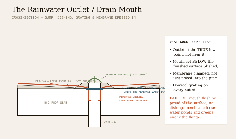
The outlet is where the whole roof's water is funnelled through a hole — the single busiest, wettest point on the surface. It deserves the most careful detail, yet it is routinely reduced to a pipe cast through the slab with the membrane poked loosely into it.
A good drain mouth, shown below, has four features: it sits at the true low point of the fall; it is dished so the surface falls locally into the mouth (the mouth set below the finished level, never flush or proud); the membrane is dressed down into the outlet and clamped with a ring or puddle flange so water cannot creep under it; and it carries a domical grating (leaf guard) to keep debris out of the pipe.
| Outlet detail | What good looks like | Common failure |
|---|---|---|
| Position | At the genuine low point of the falls | Near but not at the low point; water ponds beside it |
| Level | Mouth set below finished surface, dished in | Mouth flush or standing proud; water never fully drains |
| Membrane | Dressed into the mouth and clamped with a ring | Membrane cut short or poked in loose; water creeps under |
| Sump | Recess formed to receive the outlet body | Outlet forced into a straight cored hole, no room to dress |
| Grating | Domical leaf guard on every outlet | No guard; pipe blocks and the roof floods |
Detailing the outlet is only half the job; sizing it to the local rainfall intensity is engineering — see the Roof Drainage Guide — and every roof also needs an independent emergency overflow (a scupper or second outlet) set slightly above the main mouth so a blockage cannot turn the roof into a tank.
Expansion and movement joints
A large roof, or one split across two structural blocks, moves — thermally every day and structurally over its life. If the waterproofing is laid rigidly across a moving joint, it tears exactly along that line. The detail has to let the joint move while staying sealed.
The good detail raises the joint above the water: a pair of kerbs (upstands) on either side of the joint, with the membrane carried up and over each kerb, and a flexible loop or preformed cover bridging the gap so movement is absorbed in the loop, not the membrane. Never carry the waterproofing flat and unbroken across a live joint, and never bury a movement joint under a hard, brittle finish that will crack over it. Where a movement joint meets a parapet or an outlet, that intersection is a double-junction and needs a purpose-made three-dimensional detail, not two flat details forced to meet.
Roof-to-wall and abutment flashings
Wherever a roof runs up against a taller wall — a stair block, a lift machine room, a neighbouring rising wall, a chimney — the junction is an abutment, and it is sealed with a flashing. The principle is the same as the parapet: the roof membrane turns up the rising wall as an upstand, and its top edge is protected and terminated into the wall so water cannot get behind it.
On a masonry rising wall the termination is a chase and, ideally, a stepped or apron flashing lapping over the upstand and let into the wall. On a framed or panelled wall the roof upstand is covered by an apron flashing fixed to the wall and lapping down over the roof turn-up. Two rules never change: water always laps the way it flows (upper piece over lower piece, never the reverse), and the flashing must be let into or fixed to the wall, not just leaned against it. A flashing that only rests on the roof, with its top edge open to the wall, is a funnel pointing inward.
Box gutters and valleys
Internal box gutters and roof valleys concentrate the water from large areas into a narrow channel — they carry the most water and, being low, are the first to pond, silt and overflow. A good box gutter has a positive, generous fall along its length, an adequate width and depth for the catchment, and upstands high enough on both sides that a surge cannot overtop the edges into the building. Sole plates, outlets and any laps in the gutter lining are the vulnerable points; the lining should be continuous or fully welded, dressed over both upstands, and stopped high.
On tile and metal roofs, the valley where two slopes meet is lined with a valley gutter (metal or membrane) running well under the tiles or sheets on both sides, with the covering cut clean to a straight margin so water is caught by the valley and cannot run sideways under the tiles. Undersized valleys, short laps and mean upstands are the classic causes of valley leaks during a heavy burst.
The fall: the detail underneath every detail
Every junction detail above assumes water is moving toward the drains. That movement is the fall (slope) — the single most important detail on a flat roof, and the one most often skimped. Created by a screed to slope laid before the waterproofing, the fall decides whether water reaches the outlets or strands in low spots, where it does the damage that finds every weak junction.
| Location | Typical minimum fall (rule of thumb) | Note |
|---|---|---|
| Flat RCC roof / terrace | ~1 in 100 (about 1%) | Common minimum; steeper (1 in 80) resists ponding better |
| Exposed terrace, heavy rain | ~1 in 60 to 1 in 80 | Steeper fall clears intense monsoon bursts sooner |
| Box gutter / valley | ~1 in 60 or steeper | Concentrated flow needs a positive, generous fall |
| Local dishing at an outlet | Extra fall into the mouth | Ensures water actually enters the drain, not sits beside it |
Treat these as sanity-checks, not design values — confirm the falls with the waterproofing system datasheet and the designer, and remember the governing rule: if you can imagine rain sitting still anywhere on the roof, so can the roof. Ponding is designed out at the screed stage; it cannot be coated over later. See the Flat Roof Waterproofing Guide for how fall and membrane work as one system.
Detailing craft: coving, priming, reinforcement and protection
Beyond the geometry of each junction, a handful of craft moves separate a durable detail from a cosmetic one. They cost little and are the first things a value-engineered job drops — and the first to leak:
- Coving. A fillet at every internal corner (slab-to-wall, slab-to-kerb, around penetrations) so the membrane never turns a sharp angle.
- Priming. The substrate is primed before the membrane so the upstand actually bonds; an unprimed upstand debonds and slides down the wall.
- Reinforcement at corners. An extra reinforcing ply or scrim bridging every internal and external corner, outlet and penetration — the places a single layer is stretched thinnest.
- Double-layering at junctions. Junctions get an additional local layer of membrane so the busiest points are also the thickest, not the thinnest.
- Protecting exposed membranes. UV-exposed membranes are protected with a screed, tiles, boards or a reflective coating; an unprotected membrane bakes, embrittles and fails at its most stressed points — the junctions — first. See the notes on blistering and peeling.
Tile roofs and metal roofs: the same logic, different details
Sloping roofs shed water by gravity across overlapping units, so the junctions move — but the principle is unchanged: the details, not the field, decide the roof.
Tile roofs (clay or concrete) are detailed at the ridge (capped and bedded, or dry-fixed with a roll and clips), hip (hip tiles bedded or mechanically fixed over a continuous batten), valley (a valley gutter running under both slopes, tiles cut to a clean margin), eave (a tilting fillet, drip and gutter so water leaves cleanly into the gutter), and verge (the gable edge closed against wind uplift and driven rain). Where a tile roof meets a wall or chimney, a stepped flashing and soaker detail carries water back onto the tiles.
Metal roofs live or die by laps, fasteners and flashings. Side laps and end laps must run the right way and be long enough for the pitch; fasteners must be driven through the crown (or per the profile) with sealing washers, correctly torqued — not overdriven (which crushes the washer) nor underdriven (which leaves a gap). Ridge and apron flashings cover the changes of plane, and sealants supplement, never replace, correct lap geometry. See the Metal Roofing Guide for profiles and fixings.
| Junction | Flat / RCC roof detail | Tile / metal roof detail |
|---|---|---|
| Perimeter | Membrane upstand up parapet, terminated in a chase | Verge closer / eave drip into gutter |
| Ridge / high point | Not applicable (single plane) | Ridge tiles bedded/dry-fixed; ridge flashing on metal |
| Valley | Internal box gutter, lined and dressed over upstands | Valley gutter under both slopes, clean tile margin |
| Penetration | Coved upstand + puddle flange / boot | Soaker + flashing, or preformed flashing to the pipe |
| Roof-to-wall | Upstand + apron/stepped flashing into the wall | Stepped flashing and soakers onto the tiles |
| Outlet / discharge | Dished, clamped outlet + emergency overflow | Eaves gutter and downpipe |
| Fixings | Membrane bonded/ballasted; no field penetrations | Fasteners with sealing washers, correct lap and torque |
Who is responsible for what
Detailing is a shared responsibility, and leaks thrive in the gaps between disciplines. A workable split:
- Architect — sets the roof geometry, parapet and coping design, penetration and equipment layout, and coordinates the details on the drawings.
- Structural engineer — the slab, falls at the structural level, expansion/movement joints and any kerbs or upstands that are structural; retains responsibility for structural design and certification.
- MEP consultant — locates and sizes penetrations, outlets and services so they can actually be detailed and are kept clear of junctions.
- Waterproofing specialist / manufacturer — provides the system-specific junction details, upstand heights, primers and reinforcement, on a datasheet the drawings must follow.
- Contractor — builds the details as drawn, in sequence (coving and screed before membrane), and is responsible for execution and safety at height.
- PMC / site engineer — inspects each junction before it is covered, because a junction hidden under a finish cannot be checked later.
A junction inspection checklist you can adapt
Use this at the pre-cover stage, junction by junction, before anything is screeded or tiled over. Adapt it to the project and the system datasheet.
- [ ] Falls confirmed by flood test or level survey; no ponding areas; water reaches every outlet.
- [ ] Coving / fillets present at every internal corner and around every penetration.
- [ ] Substrate primed where the datasheet requires it, before membrane.
- [ ] Parapet upstands carried above finished level per datasheet; terminated into a sealed chase; coping fitted.
- [ ] Penetrations on kerbs where possible; puddle flanges / boots clamped; reinforcing patch bonded; grouped and clear of junctions.
- [ ] Outlets at true low points; dished; membrane clamped; domical gratings fitted; emergency overflow present.
- [ ] Expansion / movement joints kerbed and looped; membrane not carried rigidly across.
- [ ] Abutment flashings let into / fixed to the wall; laps run the way water flows.
- [ ] Box gutters / valleys with positive fall, adequate section, high upstands, continuous or welded lining.
- [ ] Reinforcement and double-layering in place at every junction; exposed membrane protected.
- [ ] Each junction photographed and signed off before it is covered.
The one-line answer
Roof detailing is the discipline of the junctions — because roofs almost never fail in the open field, they fail where the membrane has to turn, terminate or wrap something. Cove every internal corner, carry the parapet upstand well above the finished level and lock it into a chase, seal penetrations with clamped collars on kerbs, dish and clamp the outlets and give them an overflow, kerb and loop the movement joints, lap the abutment flashings the way water flows, and give box gutters and valleys a generous fall and section. On tile and metal roofs the same logic governs the ridge, hip, valley, eave, verge, laps and fastener washers. Confirm every dimension against the system datasheet, the designer and the current standards — and inspect each junction before it disappears under a finish.
Where to go next
- The whole subject in one map: The Ultimate Guide to Roofing Systems · Roofing Knowledge Hub.
- Specify it right first: Roofing Specification Guide · build the spec with the Roofing Specification Builder.
- The systems these details carry: Roof Waterproofing Guide · Flat Roof Waterproofing Guide · Membrane vs Liquid Waterproofing.
- Get the water off the roof: Roof Drainage Guide.
- When details fail: Roof Defects Guide · Roof Leakage Diagnosis & Repair · Blistering & Peeling Waterproofing.
- The edge that keeps people safe: Terrace Safety & Parapets.
References
- National Building Code of India (SP 7), Bureau of Indian Standards — refer to its provisions on building drainage, waterproofing and roof construction by topic; the 2016 edition (SP 7:2016) has been superseded, so verify the current edition and part structure via the BIS catalogue.
- IS 3067: Code of Practice for General Design Details and Preparatory Work for Damp-Proofing and Waterproofing of Buildings — verify the current edition via the BIS catalogue.
- IS 1346: Code of Practice for Waterproofing of Roofs with Bitumen Felts — verify the current edition via the BIS catalogue.
- IS 13182 and IS 2645: waterproofing treatments and integral / admixture waterproofing for buildings — verify the current editions via the BIS catalogue.
- IS 456: Plain and Reinforced Concrete — Code of Practice (the RCC slab, kerbs and screed the details are built on) — verify the current edition via the BIS catalogue.
- IS 654 and IS 2690: clay roofing tiles and burnt-clay flat terracing tiles (tile-roof ridge, hip, valley and eave detailing) — verify the current editions via the BIS catalogue.
- IS 277 and IS 459: galvanized steel sheets and corrugated / asbestos-free sheets (metal-roof laps, flashings and fixings) — verify the current editions via the BIS catalogue.
- Actual upstand heights, falls, joint details, membrane systems and flashing gauges must follow the waterproofing manufacturer's system datasheet and the project designer; confirm any standard's current status via the BIS catalogue: https://www.services.bis.gov.in/
This is an educational best-practice overview for professionals. Site-specific detailing, structural design and statutory certification remain the responsibility of the project's licensed designer, structural engineer and contractor. Verify every dimension against the project, the waterproofing system datasheet, the current standards and the local authority, and confirm any Indian Standard's current status via the BIS catalogue before relying on it.
Export this guide
Related Guides — Deep-dive reading
Bathroom Leak Prevention India: Detailing the Junctions That Stop Water Reaching the Flat Below
Bathroom leaks almost never come from a broken pipe — they come from a badly detailed junction. Here is how to get the wall-floor corner, pipe penetrations, floor trap, nahani trap and door threshold right, plus the flood test that catches a leak before you tile.
BathroomsFlat Roof & Terrace Waterproofing
The flat RCC terrace is India's most common roof and its most common leak — because water barely slopes off it. This guide explains why flat roofs are the hardest to keep dry, the traditional methods (brick-bat coba, mud-phuska, lime terracing, china-mosaic) versus the modern ones (liquid membranes, torch-applied felts, inverted systems), the fall-to-drain and layered build-up that actually stop leaks, and how to re-do a leaking old terrace. Plain language, India-grounded.
RoofingWaterproofing Failures Explained: Why Systems Fail and How to Spot It
Why waterproofing so often leaks again within a year or two — the weak links in the system, the junctions that really fail, the flood test everyone skips, and how to tell a real repair from a cosmetic patch.
Structural SafetyRelated Tools — Try Free
Rainwater Tank Sizer
How big should your rainwater tank be? Computes annual harvest, recommended tank capacity in litres, water-bill savings, and payback — for 10 Indian cities.
RWH CalculatorMonsoon-Readiness Checklist
Pre-rain home audit across 9 categories — terrace, drains, waterproofing, electrical, HVAC, pest, vehicles, documents.
Seasonal AuditPlumbing Pressure-Test & Leak Checklist
Pre-closure pressure and leak test — 9 categories, 60+ checkpoints across water supply, drainage, fixtures, waterproofing, hot water, tanks.
Pre-Closure Test