
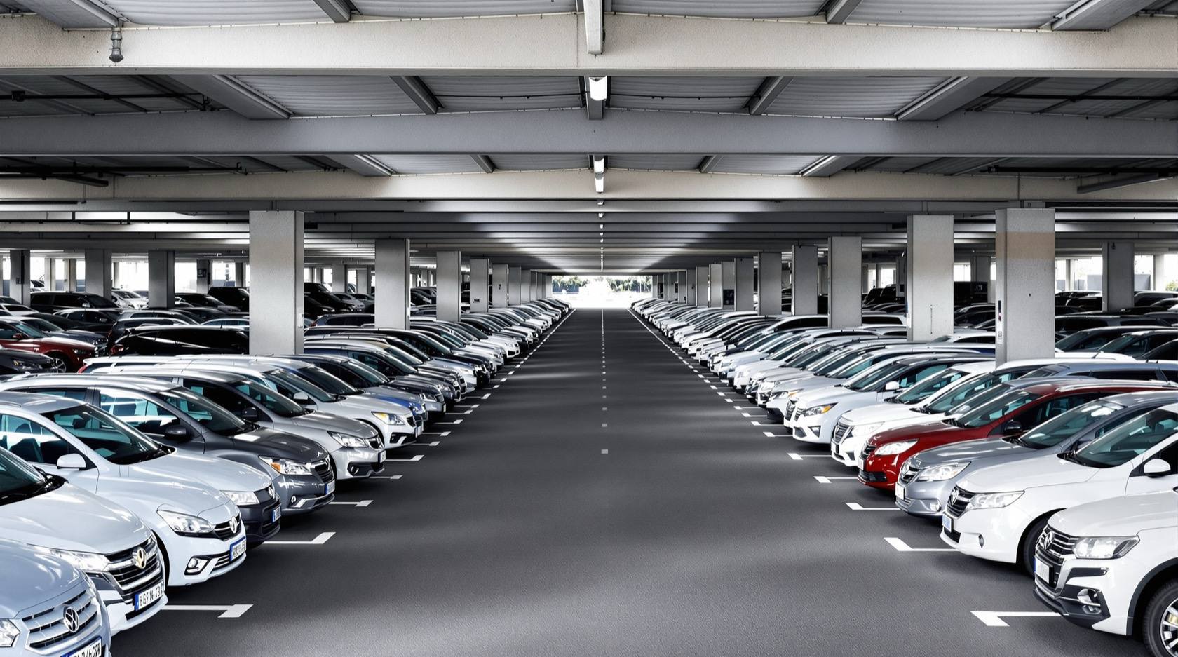
Parking Capacity and Efficiency in India: Maximising Bays per Floor (2026)
The design guide to fitting the most usable, safe bays into a given area — the gross-area-per-car efficiency metric, the big levers (layout angle, double-loaded aisles, a column grid aligned to bays, external ramps, minimal dead circulation), where mechanical systems change the maths, and the honest limit: never squeeze a count out of accessibility, egress or turning.
Two parking floors can occupy the exact same area and yet one holds a third more cars than the other. The difference is not luck — it is efficiency: how little "overhead" area (aisles, ramps, columns, dead corners) each parked car has to carry. Where the parking space requirements guide answers "how many bays must I provide", this guide answers the sister question every developer, society and designer eventually asks: "how do I actually fit them in without making the parking miserable or unsafe?"
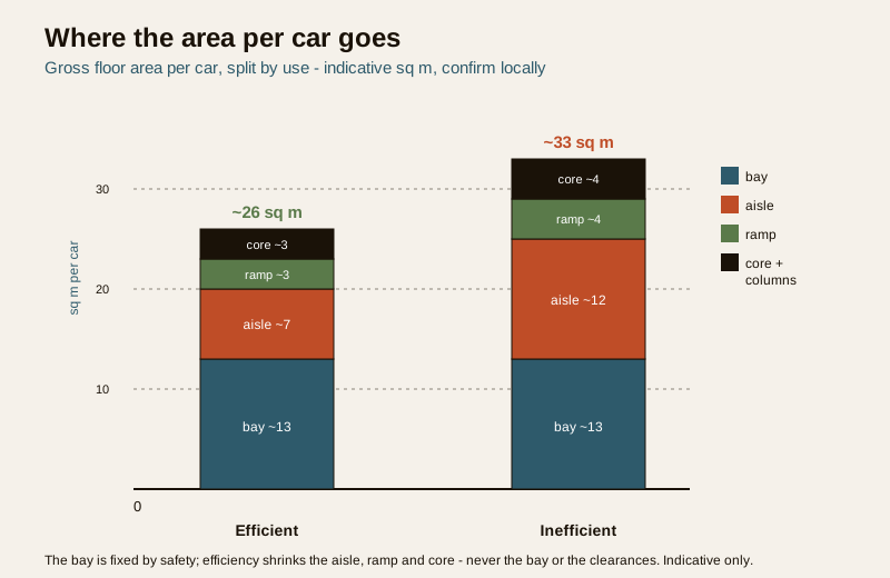
Efficiency has a single honest measure — the gross floor area divided by the number of cars, everything included. A tight, well-planned basement can land around 25 to 28 sq m per car; a clumsy one drifts to 32 sq m or more and quietly loses whole bays per floor. This guide walks the levers that move that number — layout angle, aisle loading, the column grid, ramp placement, dead circulation — and it links out to the tools and sibling guides that carry the arithmetic and the detail, chiefly the layout and aisle design guide and the Parking Capacity Calculator.
But efficiency is a servant, not a master. The moment "more bays" starts eating an accessible bay, a fire exit, headroom or the turning space a car actually needs, you have stopped designing parking and started designing a trap. Every lever below comes with the same caution: squeeze the geometry, never the safety.
Scope & how to read this. Every area figure, grid and clearance here is typical and indicative to help you plan and compare — confirm bay counts, Equivalent Car Space (ECS), aisle widths, ramp gradients, ventilation, fire egress and structure against NBC (SP 7:2026) and your local development-control regulations / municipal bye-laws. Basements, podiums, ramps, ventilation, fire safety, structure and mechanical parking equipment are life-safety, consultant-led work: you plan and choose the strategy, but a licensed structural or MEP engineer, the equipment vendor and the AHJ / fire officer design, certify and sign it off.
The one metric that matters: gross area per car
Bay count on its own tells you nothing about efficiency — a bigger plot always parks more cars. The useful number is gross area per car: take the whole parking floor plate (bays plus aisles plus ramps plus the lift/stair core plus columns and dead space) and divide by the number of cars it holds. Lower is more efficient.
| Efficiency band | Indicative gross area per car | What it usually means |
|---|---|---|
| Very efficient | 25 to 27 sq m | 90-degree double-loaded bays, external ramp, grid aligned to bays |
| Typical / good | 27 to 30 sq m | Sensible layout, one internal ramp, minor dead corners |
| Loose | 30 to 32 sq m | Angled bays, single-loaded runs, or an awkward plot |
| Inefficient | 32 sq m and up | Misaligned columns, wide dead circulation, poor ramp placement |
These bands are indicative and bundle everything on the floor — they are a planning yardstick, not a code value. A single home garage or a stilt with a handful of bays will not behave like a big basement; efficiency thinking pays off most at scale, from a housing-society basement upward. The number you should actually chase for a real scheme comes out of the Parking Capacity Calculator once you feed it your plate and bay size.
Where does a car's area go? Roughly: the bay itself is only about half of it; the aisle it opens onto is the next big slice; then ramps and the lift/stair core, and finally the columns and dead space that good design minimises. The whole game of efficiency is shrinking the last three without touching the bay or the safety margins.
The biggest lever: layout angle
Nothing moves efficiency more than the angle the bays sit at, because it trades bay-packing against aisle width. This is covered in depth in the layout and aisle design guide; the efficiency summary is:
- 90-degree (perpendicular) bays pack the most cars per metre of wall and let one aisle serve bays on both sides — but they need the widest aisle (indicatively 5.5 to 6.0 m) because the car turns in squarely. For most Indian basements and stilts this still wins overall, and it is the default efficient choice.
- 60 / 45-degree (angled) bays are easier to drive into, so the aisle can be narrower (a one-way aisle of ~3.5 to 4.5 m), but each angled bay wastes a triangular sliver and you usually lose the two-way, both-sides advantage. Angled layouts often suit one-way ramped floors or awkward plots more than raw efficiency.
- Parallel bays are the least efficient per car (long bays, one side only) and are for kerbsides and leftover edges, not for filling a plate.
The honest rule: perpendicular, double-loaded, two-way is the efficient default; reach for angled only when the plot geometry or a one-way circulation plan genuinely favours it. Confirm every aisle width against your bye-laws before you bank the saving.
Double-loaded beats single-loaded
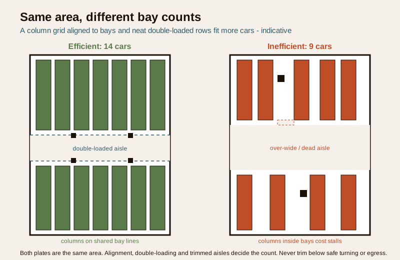
An aisle is pure overhead — it holds no cars. So the fewer aisles per car, the better. A double-loaded aisle has bays on both sides, so one run of aisle is shared by two rows of cars. A single-loaded aisle serves only one row, so every car carries twice the aisle penalty.
The efficiency implication is blunt: always try to double-load. A single-loaded run (bays on one side, a wall or ramp void on the other) can add several square metres per car of pure aisle overhead. Single-loading is sometimes unavoidable — along a boundary wall, beside a ramp, or where a level change leaves a one-sided strip — but treat every single-loaded run as area you are spending and ask whether the plate can be re-planned to pair it up.
Align the column grid to the bays
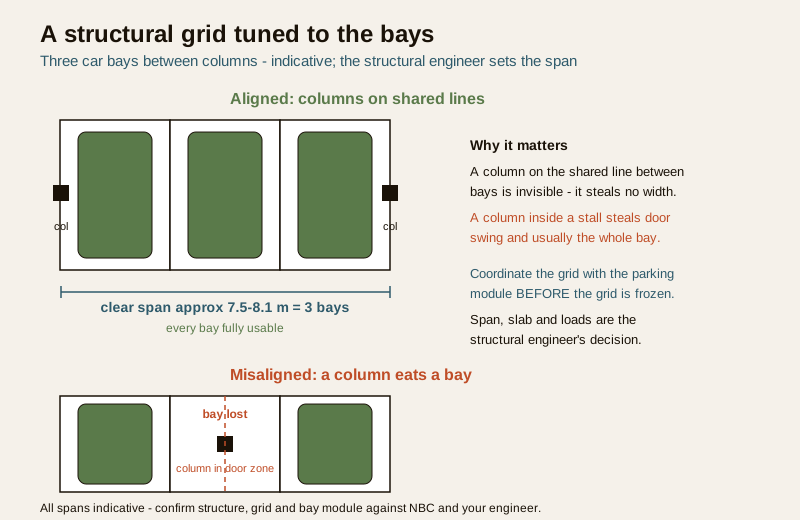
Basements and podiums are structures, and the column grid is set by the building above and the structural span. Get the grid wrong for parking and you lose bays to columns landing in door zones or mid-bay; get it right and the structure disappears into the bay lines.
The well-known rule of thumb is a structural bay that spans three car bays between columns — roughly a 7.5 to 8.1 m clear span carrying three ~2.5 m stalls — so columns fall cleanly on the shared lines between bays, not in them. A column that lands inside a stall costs door-swing and often the whole bay; a grid tuned to three-bays-per-span keeps that from happening and is one of the highest-value efficiency decisions on the whole project.
This is emphatically a structural engineer's call — span, slab depth, loads and the frame above all drive it, and it must be coordinated early, before the grid is frozen. Your job as the person planning the parking is to raise it in time: ask the structural engineer to test the grid against the parking bay module while both are still on paper.
Ramp placement: get it off the floor plate
A ramp inside the parking floor is a big chunk of area that parks no cars and often sterilises the bays beside it. Where the plot allows, an external ramp (run up the side of the building or in its own well) frees the whole internal plate for bays and is one of the cleanest efficiency wins available.
- External / peripheral ramp — best for efficiency: keeps the floor plate almost entirely for parking. Needs plot width and careful entry geometry.
- Internal straight ramp — simple, but eats a straight strip of every floor it passes.
- Helical / spiral ramp — compact in plan and good for tall stacks, but a specialist structural and geometry exercise.
- Split-level (skip-stop) — half-level ramps between staggered decks; efficient on tight or sloping plots but must be driven by the ramp design guide and an engineer.
Whatever the choice, ramp gradient, transitions and headroom are code-and-safety items, not efficiency knobs — size the gradient with the parking ramp gradient calculator and confirm it against NBC and local rules. A ramp that is too steep to be safe is not "efficient", it is a hazard.
Kill the dead circulation
After angle, loading, grid and ramp, what is left is dead area — space that neither parks a car nor moves one usefully:
- Aisles wider than the turning geometry actually needs.
- Stub aisles and dead-end runs a car cannot loop out of.
- Awkward corners and re-entrant angles where a bay will not fit.
- Over-generous circulation "just in case", which quietly costs bays every floor.
The fix is disciplined: make every aisle exactly as wide as the turning radius and bye-law demand and no wider, loop circulation so there are no dead ends, and rationalise the plate so corners carry bays or clearly become plant/service space rather than vague voids. Tighten dead circulation with the parking turning radius calculator so you trim to the real geometry, never below it.
Where mechanical systems change the maths
When the plate is genuinely too tight for conventional bays, mechanical and automated parking rewrites the area equation — stack, puzzle and tower systems park cars in the vertical dimension and can roughly double or better the cars per footprint by shrinking or eliminating the drive aisle. This is the subject of the mechanical parking systems guide, and the efficiency headlines are:
- A simple two-level stacker can nearly double a bay's yield where headroom allows.
- Puzzle and tower systems trade the aisle for machinery and retrieval time, so footprint efficiency rises but you buy a maintenance contract (AMC), a power-fail plan and a wait to retrieve a car.
- The honest cost is operational, not just spatial: throughput, reliability and upkeep, all vendor-and-engineer territory.
Mechanical systems are consultant-and-vendor-led, life-safety equipment. Use them to solve a real spatial constraint, not to chase a headline count on a plate that could take conventional bays comfortably.
The efficiency levers at a glance
| Lever | Effect on area per car | Caution |
|---|---|---|
| Perpendicular (90 deg) double-loaded bays | Lowest area per car; best default | Needs the full aisle width — never narrow it below turning need |
| Angled (60 / 45 deg) bays | Can lower area on one-way plates | Wastes triangular slivers; often loses both-sides sharing |
| Double-loaded aisle (bays both sides) | Big saving vs single-loaded | Not always possible along walls / ramps |
| Column grid aligned to bays (3 bays / span) | Recovers bays lost to columns | Structural engineer's call; coordinate before grid freezes |
| External / peripheral ramp | Frees the internal plate | Needs plot width and safe entry geometry |
| Minimise dead circulation | Recovers whole bays per floor | Never trim an aisle below the turning radius or egress need |
| Mechanical / stack systems | Can double cars per footprint | Life-safety equipment; AMC, power-fail plan, retrieval time |
The line you never cross
Every lever above is geometry. None of them is a licence to shrink the things that keep parking safe and usable. The count is never worth:
- An accessible bay or its transfer aisle — non-negotiable, on a step-free route; see car parking dimensions.
- Fire egress — exit stairs, travel distances, refuge and the fire tender's access are set by NBC and the fire officer, not by your bay count.
- Headroom and clearance — the vertical envelope from the headroom and clearance guide protects vans, ducts and sprinklers.
- Turning space — a bay you cannot drive into is not a bay.
- Ventilation — basement CO / exhaust extract is life-safety MEP, sized by an engineer.
Capacity-efficiency review checklist
| Check | What to confirm | Who confirms |
|---|---|---|
| Gross area per car | Computed for the real plate and bay size | Designer + capacity calculator |
| Layout angle | Perpendicular double-loaded unless plot dictates otherwise | Designer, against bye-law aisle widths |
| Aisle loading | Every run double-loaded where possible | Designer |
| Column grid | Aligned to bays (~3 bays per span); no column in a stall | Structural engineer |
| Ramp placement | External / peripheral if plot allows; gradient safe | Structural engineer + ramp guide |
| Dead circulation | No stub aisles; widths trimmed to turning need, not below | Designer |
| Accessible bays | Count, width, transfer aisle, step-free route intact | Per NBC (SP 7:2026) + local rules |
| Fire egress & ventilation | Exits, travel distance, extract all preserved | Fire officer / AHJ + MEP engineer |
| Mechanical option | Only where a real constraint justifies it; AMC + power-fail plan | Vendor + engineer |
How it connects
- Sits under the Parking and Garage Design hub and pairs directly with the parking space requirements guide that sets the count you are trying to fit.
- The angle, aisle and geometry levers are detailed in parking layout and aisle design, vehicle turning radius for parking and parking ramp design.
- When a plate is too tight for conventional bays, cross to mechanical parking systems; for the floor types that host these layouts, see basement parking design and podium parking design.
- Bay sizing that these figures assume comes from car parking dimensions and parking headroom and clearance; the surface under an efficient plate is in parking area flooring, and security of the parked cars lives in the Parking and Garage Security library.
- Do the arithmetic with the Parking Capacity Calculator, and size the geometry with the parking ramp gradient calculator and the parking turning radius calculator.
Key takeaways
- Efficiency has one honest measure: gross area per car, everything included — indicatively 25 to 32 sq m, and lower is better.
- The layout angle is the biggest lever: perpendicular, double-loaded, two-way bays are the efficient default; reach for angled only when the plot genuinely favours it.
- Double-loaded aisles beat single-loaded — every single-loaded run spends several square metres of pure overhead per car.
- A column grid aligned to the bays (about three car bays per structural span) recovers the bays that misaligned columns quietly eat; raise it with the structural engineer before the grid freezes.
- An external ramp frees the whole internal plate; minimising dead circulation recovers whole bays per floor.
- Mechanical systems can double cars per footprint but buy a maintenance contract, a power-fail plan and retrieval time — use them for a real constraint, not a headline count.
- Never squeeze the count out of an accessible bay, fire egress, headroom, turning space or ventilation — those are life-safety, not efficiency knobs. Every figure here is indicative; confirm against NBC (SP 7:2026) and local bye-laws.
References
- National Building Code of India, NBC (SP 7:2026), Bureau of Indian Standards — parking, circulation, ramp, ventilation, egress and accessibility provisions.
- Local development-control regulations / municipal bye-laws — Equivalent Car Space (ECS), off-street parking ratio, aisle and ramp requirements (city- and use-specific).
- IS codes and BIS guidance on structural design and barrier-free / accessible built environments — grid, spans and accessible parking provisions.
- Mechanical and automated parking equipment vendor data — footprint, headroom, throughput and maintenance requirements for stack, puzzle and tower systems.
- Housing-society and RWA parking allotment norms — any additional local society requirements on layout and allocation.
All area-per-car figures, grids, gradients and clearances here are indicative planning aids only; confirm the governing values against NBC (SP 7:2026) and your local development-control regulations / municipal bye-laws, and have a licensed structural or MEP engineer, the equipment vendor and the AHJ design, install, certify and sign off the parking layout, ramps, ventilation, fire safety and any mechanical system.
Export this guide
Related Guides — Deep-dive reading
Mechanical Parking Systems in India: Stack, Puzzle and Tower (2026)
A planning and procurement guide to mechanical and automated car parking — two/three-level dependent stack parkers, semi-automated puzzle matrices, automated towers and pit stackers — how each works, roughly how much footprint it saves, retrieval convenience, cost bands, and the honest caveats: power, backup, AMC, a power-fail retrieval plan, and vendor + structural + electrical coordination.
ParkingAccessible Parking Design in India: Barrier-Free Bays and Routes (2026)
The barrier-free parking guide for Indian buildings — who accessible parking serves and why it is a legal right under the Rights of Persons with Disabilities Act 2016, the wider bay plus shared transfer aisle, the step-free route to the lift or entrance, kerb ramps and level thresholds, the international symbol and signage, how many bays to provide, and the universal-design thinking that helps everyone.
ParkingEmergency Exit Planning in India (2026): Number of Exits, Travel Distance & Two-Way Escape
The building-scale means of egress that a home escape plan sits inside: why you need two independent, remote exits, how travel distance and exit width scale with occupant load, and why exits must open outward, discharge to safety, and never be locked.
SecurityRelated Tools — Try Free
Parking Capacity Calculator
How many car bays fit in a floor area, or how many a building must provide from its built-up area and a parking ratio.
Parking CalculatorParking Ramp Gradient Calculator
Ramp gradient, horizontal run, sloped length and transition zones from the floor-to-floor height and a target slope.
Parking CalculatorStructural Modification Approval Checklist
41 items across structural assessment, society approval, municipal compliance, and safety.
Approval Checklist