
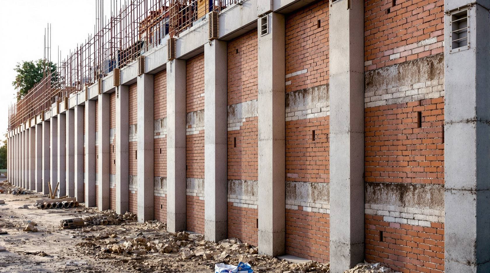
Compound Wall Piers and Columns in India: Spacing, Reinforcement and Stability (2026)
Why a long, free-standing boundary wall needs intermediate piers or RCC columns to stay up — the physics of overturning in plain terms, thickened masonry piers vs reinforced-concrete columns on footings, indicative spacing that an engineer sets to your height and wind zone, the coping or tie beam that braces the top, and where to break a long run with movement joints.
A compound wall looks simple — a strip of masonry standing on the ground — but a long, tall, free-standing wall is one of the more deceptively demanding structures on a plot. It has almost no depth to resist a sideways push, it catches the wind like a sail, and it has nothing leaning on it to hold it upright. Left as a plain unbraced ribbon of brick or block, a tall wall wants to topple, and when a boundary wall falls it can fall on a person. The quiet heroes that stop that are the piers and columns spaced along its length, and the coping or tie beam that ties the top together.
This is the piers-and-columns guide for the Compound Walls and Gates hub. It sits between the compound wall foundation guide, which covers the footing every column lands on, and the compound wall construction guide, which covers the build sequence. It also leans on the material choices in the compound wall design guide. Here the single job is to explain, in plain terms, why the wall needs bracing at intervals and what that bracing looks like — so you can tell a well-conceived wall from a flimsy one and ask your engineer the right questions.
Scope & how to read this. Every spacing, height and bar size in this guide is typical and indicative to help you understand and plan — never a specification you build to. Pier and column spacing, reinforcement and the check against wind and overturning are designed and signed off by a licensed structural engineer, sized to your wall's height, your wind zone and your soil. Confirm everything against the relevant IS codes (IS 1905 for masonry, IS 456 for RCC, IS 1904 for foundations, IS 875 for wind load) and NBC (SP 7:2026). A tall, unbraced or badly-jointed wall can collapse and kill — this is life-safety, not decoration.
Why a plain wall wants to fall over
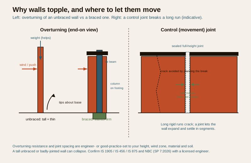
Picture a wall from the end, as a thin vertical slab standing on the ground. Two things act on it. Gravity pulls its own weight straight down, which is helpful — a heavy wall is harder to tip. Sideways force pushes on its face: wind pressure across a long run, a leaning crowd, a knock from a vehicle, or in a retaining situation the push of earth behind it. That sideways force tries to rotate the whole wall about its bottom edge, like pushing over a domino. Engineers call this overturning, and the wall stays up only while its own weight (and the grip of its footing) resists that rotation with a bigger restoring effect than the push.
The trouble is that a compound wall is tall and thin. It presents a large face to the wind but has very little thickness to give it a stable base — a poor ratio of width to height. The taller and thinner it gets, the more wind it catches and the less it has to resist tipping, so the margin shrinks fast with height. This is exactly why a knee-high garden wall needs almost nothing while a 2 m security wall is a real structural problem. The wind loads on buildings guide explains how that pressure grows with height and exposure, and why a coastal or open site in a high wind zone is far more demanding than a sheltered urban plot.
There are three honest ways to make a thin wall safe against toppling, and good design usually blends them: make it thicker or heavier (expensive and clumsy for a long boundary), brace it at intervals with piers or columns so no single stretch acts alone, and tie its top together with a continuous coping or tie beam so the whole wall shares the load. Bracing at intervals is the workhorse, and it is what the rest of this guide is about.
Piers and columns: bracing the wall at intervals
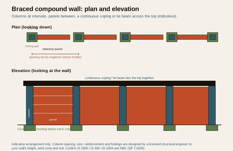
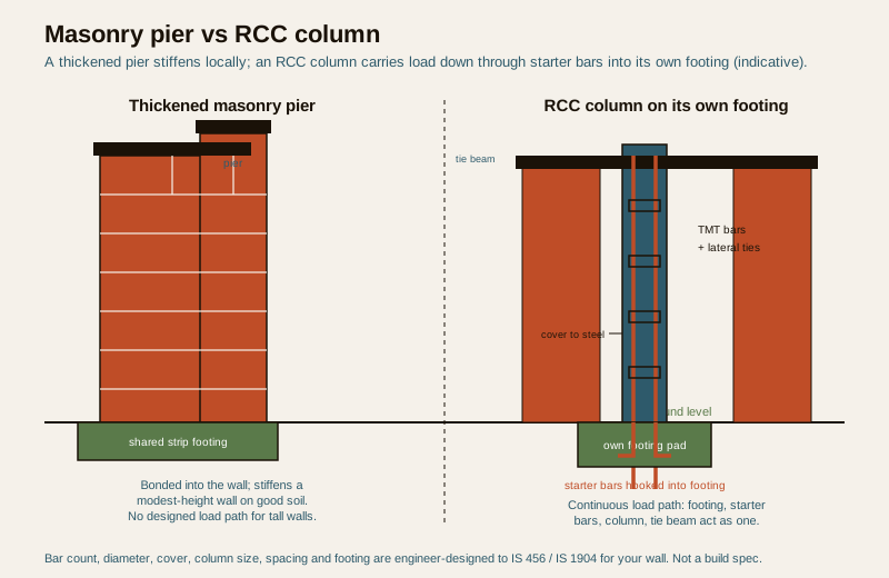
A pier (also called a pilaster) is a local thickening of the masonry at intervals along the wall — a fat vertical rib, often a brick or block deeper than the panel between. It stiffens the wall the way a fold stiffens a sheet of paper: the panels between piers are shorter and better held, so each stretch is far harder to bow or tip. Simple thickened-brick piers suit modest-height walls on good soil, where the loads are gentle and no steel design is strictly needed.
A reinforced-concrete (RCC) column does the same job far more powerfully. It is a cast concrete post with a cage of TMT reinforcement steel inside, standing on its own footing and carrying the wall's sideways load down into the ground as a designed load path. Where a masonry pier only stiffens, an RCC column can be engineered to resist a calculated overturning force — which is why taller, exposed, retaining or high-security walls almost always use RCC columns rather than plain piers. The masonry panels then simply fill the bays between columns and lean on them.
How spacing and reinforcement are decided
Here is the part readers most want as a number and most need to treat with care. Columns are commonly spaced every few metres along a wall — often somewhere in the region of 2.5 to 3.5 m for an ordinary residential wall — and they are placed closer together as the wall gets taller or the wind zone gets harsher, because each panel between them has to be kept short enough to stay stable. But that is a description of typical practice, not a spacing to build to. The actual figure falls out of a calculation your engineer does from the wall's exact height, the design wind pressure for your zone and exposure, the material, and the soil under the footings. A 1.5 m wall on a sheltered plot and a 2.4 m wall on an open coastal site are different problems with different answers.
The same is true of reinforcement. The column's bar count and diameter, the footing size, and the starter bars that stitch the column to its footing are all designed to IS 456 and IS 1904 by the engineer — never eyeballed by the mason on site. What you can usefully watch for is that the concrete strength is right, that the steel is genuine TMT with proper cover, and that the starter bars are actually cast into the footing before the column goes up, not tucked in as an afterthought. You can sanity-check quantities with the steel quantity calculator and the concrete volume calculator once your engineer has given you the design — as planning aids, not as the design itself.
| Wall situation | Typical bracing approach | Who designs it |
|---|---|---|
| Knee-high garden / planter wall (well under 1 m) | Often no piers needed; wall's own thickness is enough | Mason to good practice; engineer if any doubt |
| Ordinary residential wall on firm soil (~1.2 to 1.5 m) | Thickened masonry piers at intervals, or light RCC columns | Engineer confirms for anything but the shortest walls |
| Tall or exposed wall (above ~1.8 m, open / windy site) | RCC columns on footings at engineer-set spacing, closer for height | Licensed structural engineer — always |
| High-security, factory or institutional boundary | RCC columns, reinforced panels or cast-in-situ RCC | Licensed structural engineer — always |
| Retaining wall (earth pushing behind it) | Engineer-designed RCC — not a piers-and-panels wall at all | Licensed structural engineer — always, mandatory |
| Long straight run over uneven or made-up ground | RCC columns with movement joints; footings sized to soil | Licensed structural engineer — always |
Two rows deserve emphasis. A retaining wall — one holding back a difference in ground level — is a wholly different animal: the earth behind it pushes constantly and hard, and it is always engineer-designed as covered in the retaining walls guide, never treated as an ordinary piers-and-panels compound wall. And any wall above a modest height on an exposed site should be treated as an engineering job from the start, not retro-fitted with piers after it looks wobbly.
Pier versus RCC column, and the footing under each
The choice between a thickened-masonry pier and a proper RCC column is really a choice about how much load has to travel down to the ground and how it gets there. A masonry pier shares the footing of the wall and stiffens locally; an RCC column is a designed vertical member that gathers the panel loads and delivers them through starter bars into its own footing pad, tied continuously from footing to coping. That continuity — footing, starter bars, column cage, tie beam — is what turns a stack of separate parts into one structure that acts together.
Every RCC column therefore depends on the compound wall foundation beneath it. The starter bars must be cast into the footing so the column and its pad are one; the footing must be sized to the soil so it neither sinks nor lets the column rotate; and on black-cotton or made-up soil the footing design matters even more, because a column is only as stable as what it stands on. A beautifully reinforced column on a guessed, undersized footing is still a wall waiting to lean. This is why the foundation is engineer-designed as a set with the columns, not as a separate afterthought.
The top brace: coping and tie beam
Bracing the wall at intervals with columns only works fully if the top of the wall is tied together so every column and panel shares the load rather than each fending for itself. That top brace is the coping — the capping along the wall's crest — which on a taller or engineered wall becomes a proper RCC tie beam (a small reinforced beam running continuously along the top, linking the heads of all the columns).
Its structural job is to act as a horizontal spine: when wind pushes on one panel, the tie beam spreads that push to the columns on either side instead of letting one panel work alone. It also gives the wall a clean, finished crest and — sloped and drip-detailed — sheds rain so water does not sit on the wall and wick down into the masonry. A wall with columns but no continuous top tie is only half-braced; the coping or tie beam is what completes the frame.
Movement joints: where to break a long run
There is one more thing a long wall needs, and it is the opposite of bracing — a deliberate gap. Masonry and concrete expand and contract with heat and moisture, and the ground beneath a long wall is never perfectly uniform. Build a long, rigid, unbroken wall and those movements have nowhere to go, so the wall relieves the stress the only way it can: it cracks, usually in an ugly diagonal near a weak point. The cure is to decide in advance where the wall is allowed to move by building in control (movement) joints — full-height vertical breaks at intervals that let the wall expand, contract and settle in controlled segments instead of tearing itself.
Like spacing, the interval between joints is engineer- or good-practice-set, not a fixed number you read off a chart, and it depends on the material, the length, the exposure and the ground. What you can usefully know is that a long run should have them, that they belong at natural break points (a change in ground level, near a gate pier, at a soil change), and that they are sealed against water rather than left as open gaps. A wall built dead rigid from corner to corner over a long, uneven boundary is one that will crack — plan the breaks in.
| Element | What good looks like | Who signs off |
|---|---|---|
| Column / pier spacing | Regular, closer for taller or windier walls; panels kept short | Structural engineer sets it from height + wind zone + soil |
| Column reinforcement | Genuine TMT, correct bar count and cover, ties in place | Engineer designs to IS 456; you verify material and cover |
| Starter bars into footing | Cast into the footing before the column rises; column and pad one piece | Engineer details; site supervision confirms on the day |
| Footing under each column | Sized to the soil; deeper thought on black-cotton / made-up ground | Structural engineer, designed with the foundation |
| Coping / tie beam | Continuous along the top, ties column heads, sheds water | Engineer for a tie beam; good practice for a plain coping |
| Movement (control) joints | Full-height breaks at intervals on long runs, sealed against water | Engineer or good practice sets the interval and positions |
| Retaining situation | Treated as a designed RCC retaining wall, not a piers-and-panels wall | Structural engineer — mandatory, always |
How it connects
- Sits under the Compound Walls and Gates hub between the compound wall foundation guide (the footing each column lands on) and the compound wall construction guide (the build sequence), and builds on the compound wall design guide.
- When earth pushes behind the wall it becomes a different, always-engineered structure — see the retaining walls guide.
- The materials that make columns work: concrete strength and TMT steel, both in the Construction Materials library; the sideways force they resist is set out in wind loads on buildings.
- The deeper engineering context lives in the Structural Safety library.
- Once your engineer has a design, sanity-check quantities with the steel quantity calculator and the concrete volume calculator — planning aids, not a substitute for the design.
Key takeaways
- A tall, thin, free-standing wall is weak against a sideways push and catches the wind like a sail — left unbraced it wants to topple, and a falling boundary wall can injure or kill.
- Piers (thickened masonry) stiffen the wall locally; RCC columns on their own footings can be engineered to resist a calculated overturning force — the choice depends on height, exposure and soil.
- Columns are commonly spaced every few metres and placed closer for taller or windier walls, but the real figure comes from an engineer's calculation to your height and wind zone — it is never a spacing you build to.
- Every RCC column depends on its footing and starter bars cast as one with the foundation; a good column on a guessed footing is still a wall waiting to lean.
- The coping or tie beam braces the top so the whole wall shares the load, and movement joints let a long run expand and settle in segments instead of cracking.
- Retaining walls are always engineer-designed as a separate structure; every spacing and bar size here is indicative — confirm against IS 1905, IS 456, IS 1904, IS 875, NBC (SP 7:2026) and a licensed structural engineer.
References
- IS 1905, Bureau of Indian Standards — code of practice for structural use of unreinforced masonry (piers, pilasters and panel walls; named generally).
- IS 456, Bureau of Indian Standards — code of practice for plain and reinforced concrete (RCC columns, tie beams and reinforcement; named generally).
- IS 1904, Bureau of Indian Standards — code of practice for design and construction of foundations in soils (column footings; named generally).
- IS 875 (Part 3), Bureau of Indian Standards — design loads for buildings, wind loads (the sideways force on a free-standing wall; named generally).
- National Building Code of India, NBC (SP 7:2026), Bureau of Indian Standards — general structural-safety and design-load provisions.
- Local municipal bye-laws and development-control regulations — boundary-wall height, setback and structural-safety requirements (city-specific; these govern approval).
- Licensed structural engineer's design and quotations — the pier and column spacing, reinforcement, footing and joints for your specific wall, height, wind zone and soil.
All spacing, heights, reinforcement and dimensions in this guide are indicative planning and literacy aids only; confirm the governing specification against the relevant IS codes and NBC (SP 7:2026), and have a licensed structural engineer design, finalise and certify the piers, columns, footings, tie beam and movement joints for any tall, exposed, reinforced or retaining wall.
Export this guide
Related Guides — Deep-dive reading
Compound Wall Foundation in India: Footings, Soil and Reinforcement (2026)
The part of a boundary wall you never see is the part that decides whether it stands straight for decades or leans, cracks and falls — a plain, India-grounded literacy guide to what sits under your compound wall: how your soil drives the footing, the common footing types, how deep to go, the plinth and DPC transition, and why footing size and reinforcement are engineer-designed to your soil and wall height, never a build-to number.
Compound WallsCompound Wall Design in India: The Complete Planning Guide (2026)
The start-here field guide to planning a compound wall for an Indian home, farmhouse or plot — what a boundary wall is really for, the questions to settle before you build, the decision sequence from survey to gate to finish, an honest wall-type comparison, and where structure and security hand off to the experts.
Compound WallsThe Homeowner's Guide to Compound Walls and Gates in India (2026)
A plain-language, start-to-finish walkthrough of building a boundary wall and gate in India — plan and permit first, then material and height, foundation and structure, building and supervision, the gate, finishes, lighting and greenery, budget and long-term upkeep — with a stage-by-stage roadmap, a full planning checklist and answers to the questions every homeowner asks.
Compound WallsRelated Tools — Try Free
Cross-Ventilation Analyzer
Estimate airflow and air changes per hour (ACH) from room size, window areas, layout, and local wind — with NBC 2016 Part 8 compliance check.
Ventilation CalculatorSteel Quantity Calculator
Reinforcement steel weight from bar diameter, length and number, or estimated from a concrete volume.
Wall CalculatorStructural Modification Approval Checklist
41 items across structural assessment, society approval, municipal compliance, and safety.
Approval Checklist