
Oil & Grease Trap in an STP: Why It Matters (FOG Removal Explained)
The quiet chamber that skims fats, oils and grease out of kitchen-heavy sewage before it ever reaches the biology. What an oil and grease trap does, how its baffles work, how often it must be cleaned, and why skipping it wrecks an STP.
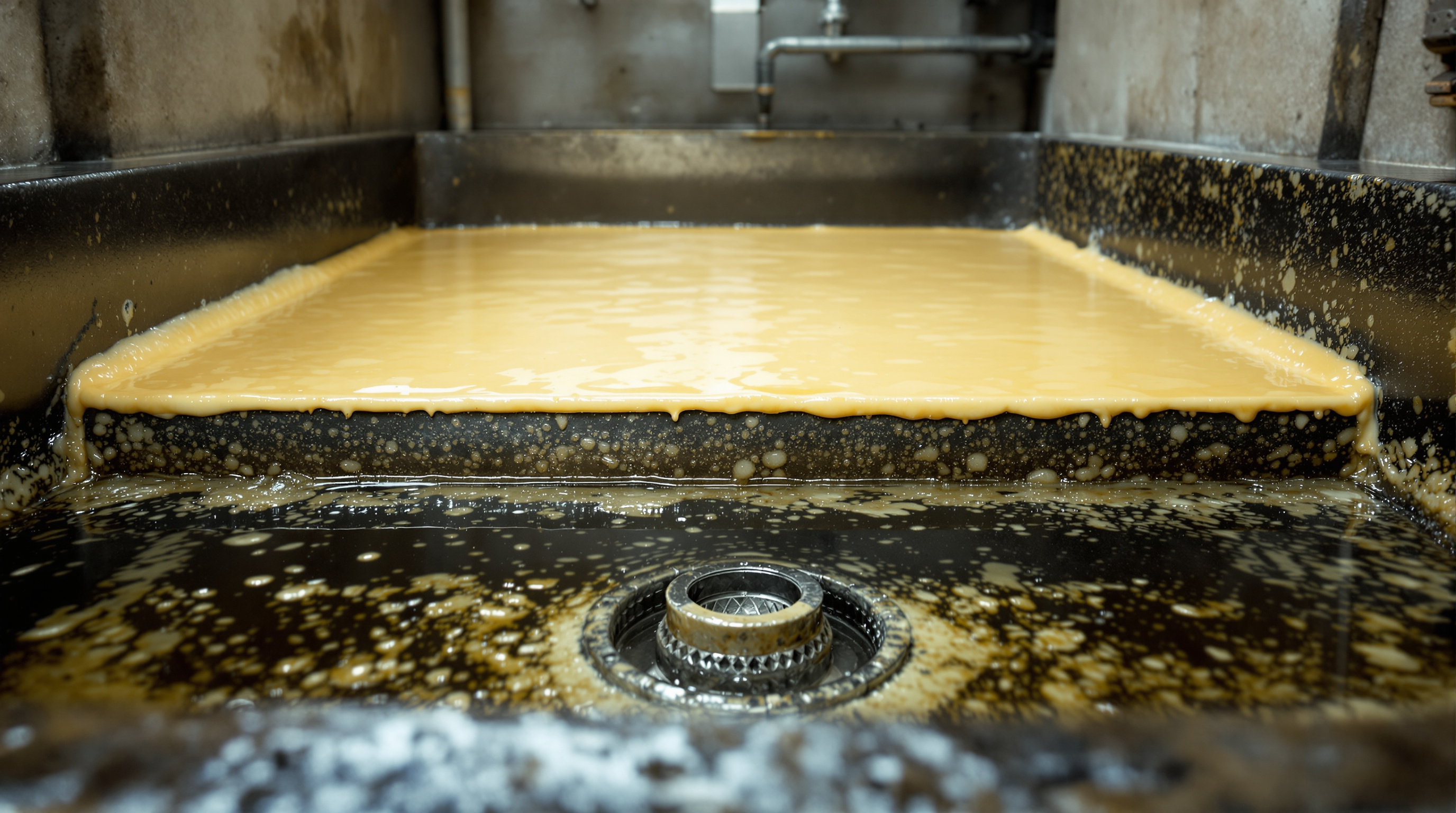
Walk into almost any STP that serves a hotel, a hostel, a hospital canteen or a large apartment block, and near the very start of the plant you will find a small, unglamorous chamber that most people walk straight past. It is often the dirtiest-looking box in the whole plant — capped with a thick, pale, waxy scum. This is the oil and grease trap, and the mess sitting on top of it is precisely the point. Every gram of that grease is a gram that did not reach the delicate biological heart of the STP downstream.
This guide explains what an oil and grease trap is, why fats, oils and grease (FOG) are so damaging that they get their own dedicated chamber, how the trap's baffles actually do their job, roughly how to size one, and — the question that decides whether it works at all — how often it has to be cleaned.
A grease trap is the only part of an STP that succeeds by failing to let something pass. Its entire purpose is to hold back the one substance that would otherwise strangle every stage after it. A trap that looks clean is usually a trap that isn't working.
If you are new to how the whole system fits together, it helps to first read what a sewage treatment plant actually is and how an STP works stage by stage. This guide zooms into one small but decisive chamber near the front of that process.
What an oil and grease trap actually is
An oil and grease trap — sometimes called a grease interceptor — is a baffled tank placed in the preliminary treatment stage of an STP, right after the bar screen chamber and usually before or alongside the equalization tank. Its job is narrow and specific: separate and hold back the floating layer of fats, oils and grease that comes mainly from kitchens, so that the rest of the plant receives sewage that is greasy-light rather than grease-heavy.
It works on the simplest physics in the building: oil floats on water. FOG is lighter than water and does not dissolve in it. Given a few quiet minutes in a chamber, the grease rises and forms a layer on the surface while the cleaner water underneath is drawn off from below. No power, no chemicals, no moving parts in the basic version — just gravity, time, and cleverly placed walls.
Not every STP has a large dedicated trap. A purely residential block with modest kitchen output may fold grease removal into the collection or equalization tank. But any building with a commercial kitchen, canteen, food court or heavy cooking load should treat the grease trap as essential, not optional.
Why FOG is such a problem
It is fair to ask why grease deserves a whole chamber when the STP has powerful biological and chemical stages later. The answer is that FOG does not just add to the pollution load — it actively sabotages the machinery meant to remove pollution.
- It suffocates the microbes. The biological heart of an STP — the aeration tank — depends on billions of bacteria breathing oxygen to eat the waste. A film of oil coats the water surface and coats the bacteria themselves, blocking oxygen transfer. Starved of air, the culture weakens and treatment collapses. You can see how central that oxygen supply is in the activated sludge process and in guides on air blowers and diffusers.
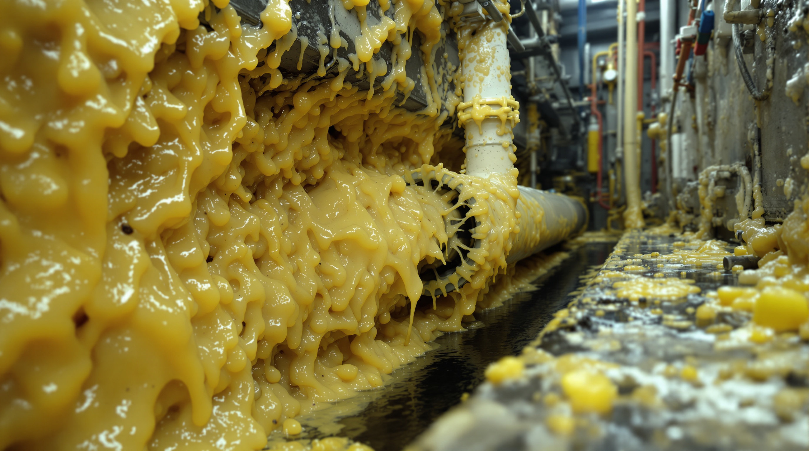
- It clings and it clogs. Grease congeals on pipe walls, pump impellers, diffuser membranes and probes. Over months it narrows pipes to a trickle and fouls the very instruments operators rely on.
- It floats the sludge. In settling tanks like the clarifier, grease traps gas bubbles in the sludge blanket and lifts it to the surface as a scum that escapes with the treated water — undoing the settling the plant just worked to achieve.
- It is hard to digest and hard to disinfect. FOG breaks down slowly, drags up BOD and COD, and shields bacteria from the final disinfection step. See how those numbers behave in the guide to wastewater characteristics: BOD, COD, TSS and pH.
In short, letting grease through is like pouring cooking oil into the plant's lungs. The trap exists so that never happens.
How the baffles do the work
The intelligence of a grease trap lives in its baffles — the internal walls that force the sewage to take a slow, indirect path so grease has time to rise and gets physically held back.
A well-designed trap uses at least two or three chambers separated by baffle walls:
1. Inlet chamber. Incoming sewage enters and immediately slows down. Turbulence is the enemy of separation, so the inlet is designed to calm the flow, not blast it across the tank.
2. Separation chamber(s). Here the water sits quietly long enough — a retention time of several minutes to tens of minutes — for grease to float to the top and heavier grit to settle to the bottom.
3. Outlet chamber. The critical trick: water leaves through a submerged outlet or a baffle that draws from below the surface, so it takes clean water from the middle while the floating grease layer is trapped behind the baffle wall.
The key design principles are simple to state and easy to get wrong:
- Draw from the middle, not the top. Inlet and outlet must pull from below the floating layer, never skim across it.
- Slow the flow. Adequate retention time and a large enough surface area let grease separate; a trap that is too small just passes grease straight through.
- Give the scum room to grow. The chamber needs freeboard so a thick grease cap can accumulate between cleanings without reaching the outlet.
Larger plants add a mechanical skimmer — a rotating belt or scraper that continuously lifts grease off the surface into a collection trough — but the underlying baffle logic is identical.
Sizing basics — directional only
Grease traps are sized on flow and retention time, not on a single formula. The bigger the kitchen load and the higher the peak flow, the larger the trap. As a directional guide only:
| Building type | Kitchen / FOG load | Grease trap emphasis |
|---|---|---|
| Residential apartments | Low to moderate | Small trap, or grease handled in the collection tank |
| Hostels, PGs, service apartments | Moderate | Dedicated trap, regular cleaning |
| Hotels, restaurants, food courts | High | Large multi-baffle trap or skimmer, frequent cleaning |
| Hospitals, corporate canteens | High, peaky | Generous sizing plus buffering upstream |
The number every design starts from is the building's daily flow. You can estimate that in a minute with the sewage generation calculator, and translate it into overall plant capacity with the STP capacity calculator. A common rule of thumb is to size the trap for a retention time in the order of 15–30 minutes at peak kitchen flow, with enough surface area for grease to rise — but final sizing should follow the plant designer and applicable CPCB/NBC guidance rather than a rule of thumb.
Cleaning frequency and O&M — where traps live or die
Here is the hard truth of grease traps: the design almost never fails, but the maintenance almost always does. A trap only works while there is empty volume for grease to collect. Once the scum layer grows thick enough to reach the outlet, every drop of FOG sails straight through into the plant — and the operator often has no idea, because from the walkway the trap looks the same.
Typical operations and maintenance:
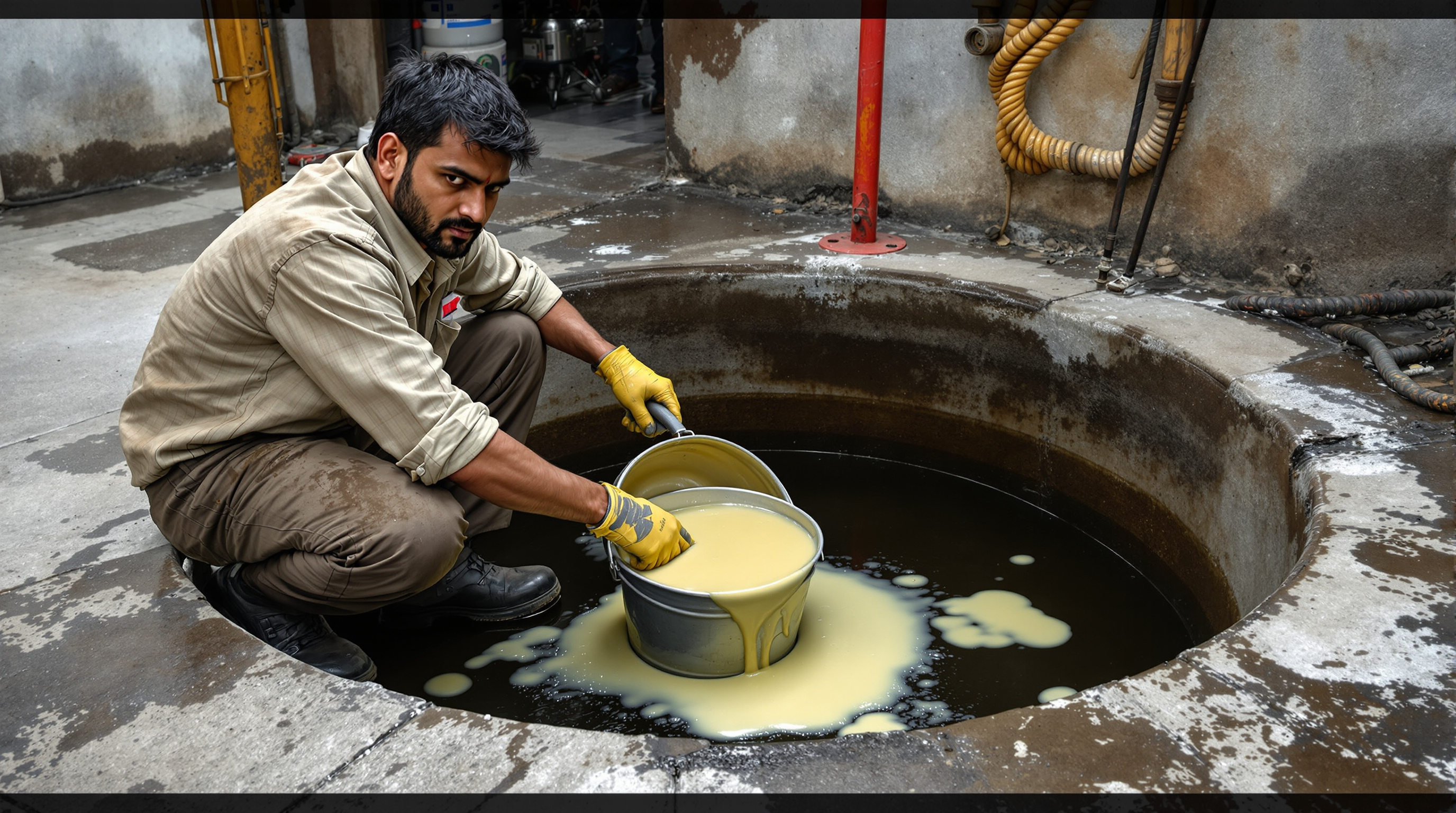
- Skim and remove grease on a fixed schedule — for a busy commercial kitchen this can mean weekly, for lighter loads fortnightly to monthly. Never wait for a problem; by then the plant is already fouled.
- Manually scoop or pump out the floating cap and the settled grit at the bottom, and dispose of it as solid waste — never wash it back into the sewer.
- Check the baffles and outlet for grease build-up and confirm the submerged draw-off is clear.
- Log every cleaning. The single best predictor of a healthy STP is a grease trap with a maintenance record.
Common failures all trace back to the same root: skipped cleaning. Overflowing scum, foul odour, grease reaching the aeration tank, floating sludge in the clarifier, and clogged pumps downstream are usually one problem wearing five costumes.
Where it sits in the treatment flow
The grease trap is a preliminary treatment device — one of the first things sewage meets, working alongside the bar screen to protect everything after it. Its place in the sequence looks like this:
- Bar screen removes rags, plastics and large solids →
- Oil and grease trap skims floating FOG →
- Collection / equalization tank buffers and evens out the flow →
- Biological treatment (aeration) destroys the dissolved organic load →
- Settling, filtration and disinfection polish the water for reuse.
You can follow the whole chain end to end in the sewage treatment process flow guide. The grease trap is the humble gatekeeper at the front — cheap to build, trivial to ignore, and quietly responsible for whether the expensive biology behind it survives.
The bottom line
An oil and grease trap does one small job supremely well: it uses gravity and a few baffle walls to hold back the fats, oils and grease that would otherwise coat the microbes, clog the pipes, float the sludge and defeat the disinfection in every stage that follows. It needs no power and almost no technology — only discipline. Size it for the kitchen load, draw the water from below the grease layer, give the scum room to grow, and above all clean it on a schedule. Do that, and the trap protects the whole STP from the front. Neglect it, and it becomes the exact bottleneck it was built to prevent.
To see how this chamber fits the bigger picture, browse the full sewage treatment plants guide library, or start at the STP pillar guide.
Export this guide
Related Guides — Deep-dive reading
The Sewage Treatment Process Flow, Explained: Every Stage From Inlet to Reuse
Follow a drop of sewage through a typical STP — inlet, screening, aeration, clarifier, filtration, disinfection and reuse — as one connected flow, with a block diagram and a unit-by-unit table, in plain language.
Sewage Treatment PlantsBar Screen Chamber: The First Line of Defence in an STP
What a bar screen chamber is, why it sits right at the inlet of every sewage treatment plant, and how it protects your pumps and pipes by catching rags, plastics and coarse solids — with manual vs mechanical screens, bar spacing and cleaning explained plainly.
Sewage Treatment PlantsHow Does an STP Work? A Step-by-Step Explanation
Follow a single drop of sewage from the building drain to reusable water — through screening, settling, the living microbial heart of the plant, and final polishing — with every stage explained in plain language and no engineering background assumed.
Sewage Treatment PlantsRelated Tools — Try Free
Sewage Generation Calculator
Estimate the daily sewage a building generates and its peak flow in KLD from occupancy, LPCD, sewage return factor and peak factor.
STP CalculatorSTP Capacity Calculator
Size a sewage treatment plant in KLD from your building's occupancy — water demand, sewage generated and recommended STP capacity.
STP CalculatorApartment STP Planner
Plan an apartment complex sewage treatment plant from flats and occupancy — get population load, sewage flow, recommended STP capacity in KLD, treatment technology and approximate space.
Planner