
STP Instrumentation Installation: Sensors, PLC Wiring & Calibration
How to physically install and wire the sensors and controls that run a sewage treatment plant — level, flow, DO and pH probes, dosing controls, PLC/SCADA wiring and the calibration you must do at install before the plant will ever run itself.
A sewage treatment plant is designed to run itself — pumps and blowers switching on rules instead of on an operator's memory. But that only happens if the instrumentation is installed correctly: the sensor mounted where it can actually read the process, the cable run so it does not pick up noise, the signal landed on the right PLC terminal, and every probe calibrated before the plant sees its first drop of sewage. This is the stage where a good design either comes alive or quietly falls apart.
This guide is the field-level companion to the STP pumps and instrumentation guide, which explains what each sensor does and why. Here we cover the how — the physical install, the wiring, and the calibration at handover. It slots between the mechanical installation and electrical installation of the plant, and feeds directly into commissioning.
An instrument that is wired but not calibrated is worse than no instrument at all — it gives the PLC a confident, wrong number, and the plant obeys it. Half of instrumentation work is the mounting and wiring; the other half is proving each reading is true before you walk away.
Before you mount anything
Instrumentation goes in after the civil and mechanical work is largely done, but the groundwork must already be in the drawings. Confirm three things first:
- The instrument schedule and loop diagram. Every sensor should have a tag (LT-01 for a level transmitter, FT-01 for a flow transmitter, AT for analysers), a location, a signal type and a destination terminal. If this document does not exist, stop and make one — you cannot wire a loop you have not drawn.
- Cable routing and glands. Instrument cables are low-voltage signal cables and must run in separate conduits or trays from power cables, ideally 300 mm apart, to avoid electrical interference. Crossings should be at right angles. Confirm the cable trays, GI conduits and cable glands are in place before power-up.
- The control panel is set and earthed. The PLC panel should be wall- or floor-mounted in a dry, ventilated location, with a dedicated instrument earth separate from the power earth. Every 4-20 mA loop depends on a clean earth reference.
Installing the field sensors
Each instrument has a right place and a wrong place. Getting the mounting wrong is the single commonest reason a brand-new plant reads nonsense.
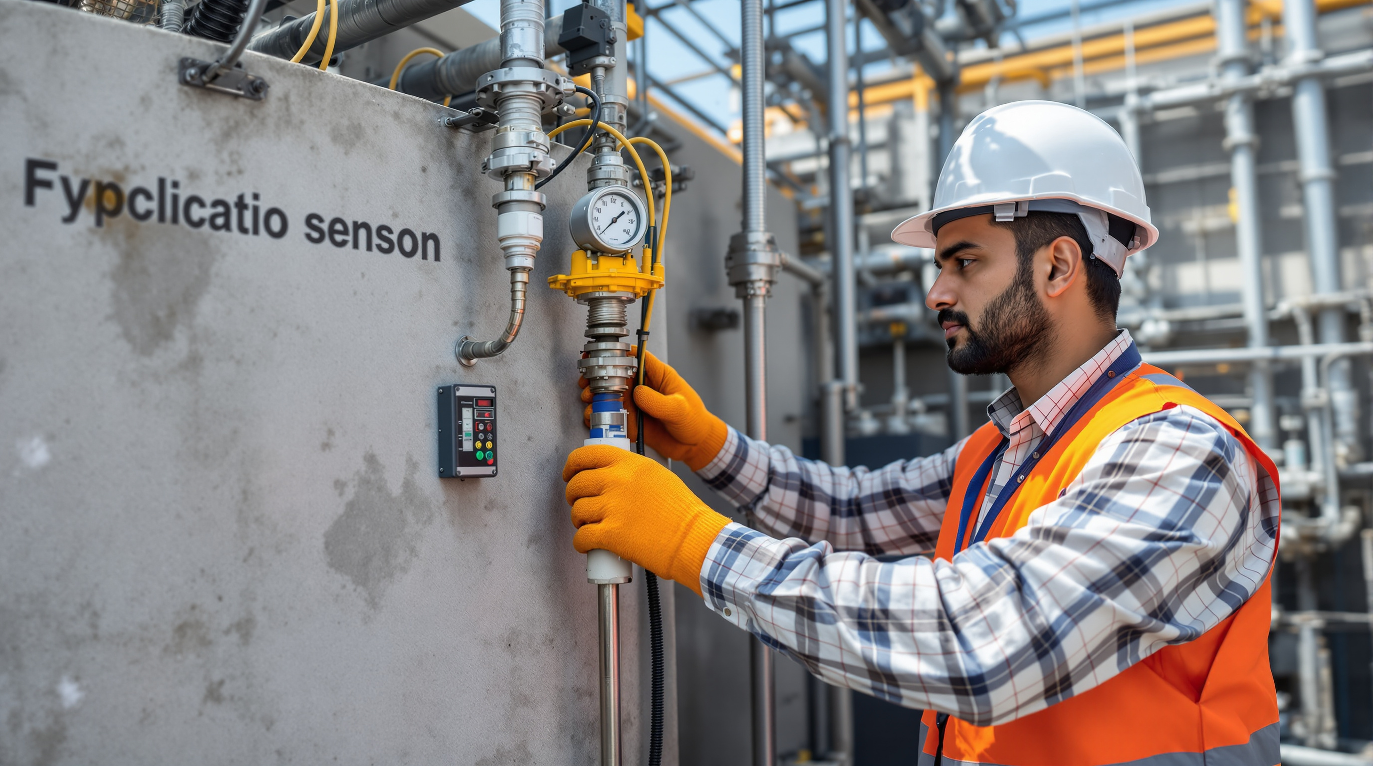
Level sensors
The most important instrument in the plant, because it starts and stops the raw and transfer pumps. Two types dominate:
- Ultrasonic level transmitters mount on a bracket above the collection and equalisation tank, aimed straight down at the water with a clear cone — no pipes, ladders or inflow splash inside the beam, and mounted above the maximum foam line. Set the empty distance and span to the actual tank depth during configuration.
- Float switches are the simple, robust backup — hung at the pump start, stop and high-high alarm levels. Fix the cable so floats swing freely and cannot snag on tank walls or pipework.
Always wire a low-level cut-off into every pump circuit. A float that fails to stop a pump running dry cooks the mechanical seal in minutes — a failure that shows up in the first week of a badly installed plant.
Flow meters
Use electromagnetic (mag) flow meters on the transfer line and the treated-water outlet — the KLD figure regulators and your own records depend on. Installation rules are unforgiving:
- Mount on a full-bore section of pipe that stays flooded; a mag meter reads garbage on a partly empty pipe.
- Give it straight run — roughly five pipe diameters upstream and three downstream, clear of bends, valves and pump outlets.
- Match the flow-arrow on the body to the actual direction, and bond the meter earth rings to the liquid.
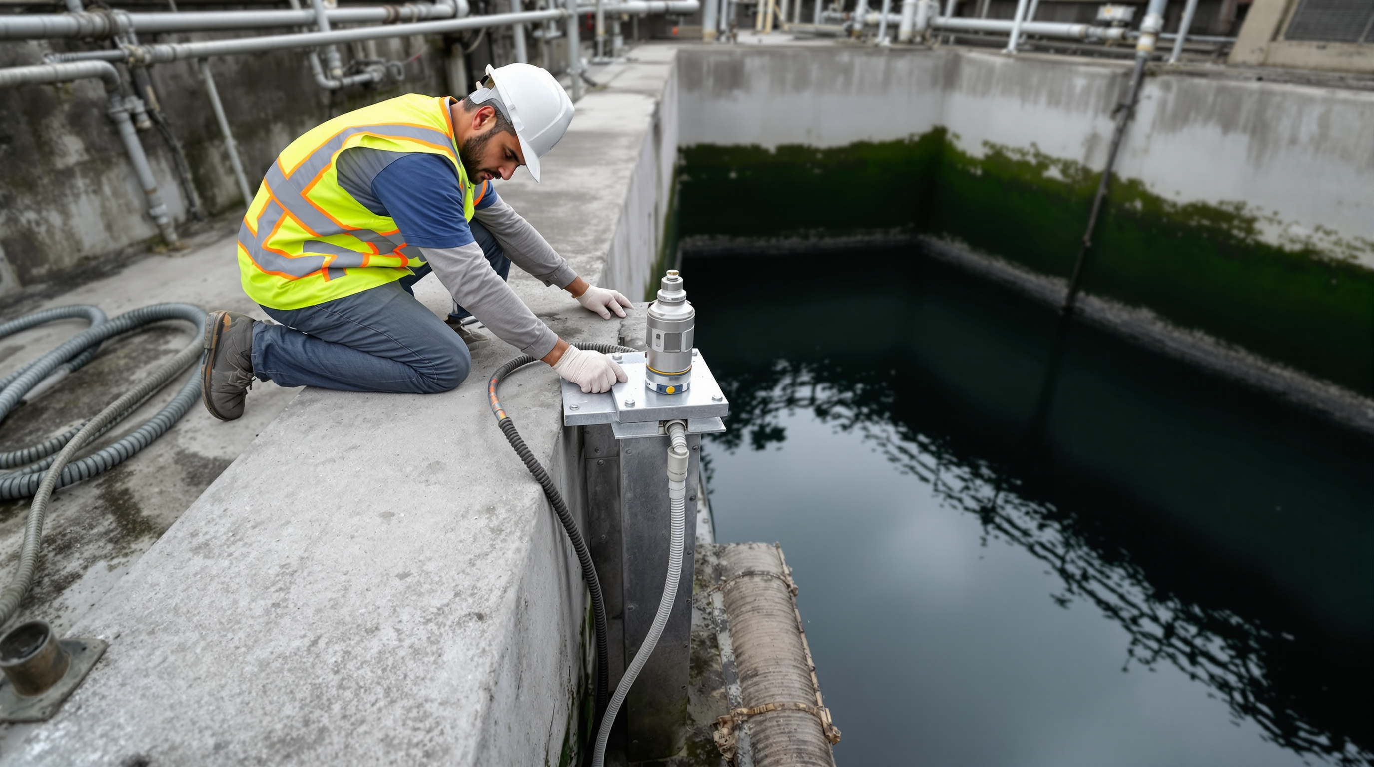
DO and pH probes
These sit in the aeration tank and are the key to the plant's biggest energy saving. Mount them on a retractable or swing-arm assembly at the tank edge so a single operator can lift the probe out for cleaning without draining anything or entering the tank. Keep the DO probe in a zone of good mixing but away from the direct blast of a diffuser, which throws false high readings. Leave a service loop of cable so the assembly can be raised fully.
Pressure and dosing controls
Fit pressure gauges and switches across the pressure sand and activated carbon filters so a clogged bed announces itself for backwash. Wire each dosing pump — chlorine at the chlorination system, any pH-correction chemical — to either a flow-proportional signal or a timer, so the dose tracks the flow rather than running blind.
Wiring the loops into the PLC
With sensors mounted, the job becomes electrical. Most STP instruments are two-wire, 4-20 mA loop-powered transmitters: the same pair of wires carries the 24 V DC supply and the signal, where 4 mA means zero and 20 mA means full scale. A handful of devices (some analysers, SCADA links) use RS-485/Modbus digital communication instead.
| Signal | Instruments | Wiring | Landed at |
|---|---|---|---|
| 4-20 mA analog | Level, flow, DO, pH transmitters | 2-core shielded, twisted pair | PLC analog input card |
| Digital ON/OFF | Float switches, pressure switches | 2-core, volt-free contact | PLC digital input card |
| Relay output | Pumps, blowers, dosing pumps | Panel wiring via contactor | PLC digital output card |
| RS-485 / Modbus | Analysers, SCADA, energy meter | Twisted pair, daisy-chained | PLC comms port |
Three wiring rules decide whether the plant works:
- Ground the shield at one end only — at the panel, never both — or you create an earth loop that injects noise into the signal.
- Observe loop polarity and the 250 Ω sense resistor / powered-input convention for every 4-20 mA device; a reversed loop simply reads dead.
- Ferrule and tag every core to its loop drawing. When a sensor misbehaves at 2 a.m. a year from now, the tag is what saves the operator.
Then bring the plant's brain to life: the PLC runs the start/stop, blower and dosing logic; on larger plants a SCADA screen (on the panel or a phone) shows every level, pump status and flow trend live. Power up the panel, confirm each input reads and each output actuates the right pump or blower, and prove the standby pump auto-starts on a duty trip.
Calibration at install — the step nobody should skip

Wiring only proves the signal arrives. Calibration proves it is true. Do this before commissioning, and log every result on the instrument sheet for handover.
- Level: with the tank at a known depth (tape-measured), confirm the transmitter reads the same. Fill and draw down to verify the pump start, stop and alarm setpoints actually fire.
- Flow: verify the mag meter against a bucket-and-stopwatch or the pump's rated duty; confirm the totaliser increments correctly in KLD.
- DO: perform an air (saturation) calibration and a zero per the maker's method; a fresh membrane and electrolyte are part of the install.
- pH: two-point calibration against buffer 7 and buffer 4 (or 9.2) solutions — non-negotiable, and repeat it at every service.
- Dosing pumps: calibrate the stroke against a measuring cylinder so millilitres-per-minute matches the loop-diagram dose.
Only when every loop reads true does the instrumentation hand a plant that can be trusted to the commissioning and trial-run teams.
The bottom line
STP instrumentation installation is where a plant earns its automation. Mount each sensor where it can genuinely read the process, run signal cable clear of power, land every 4-20 mA loop on the right PLC terminal with the shield earthed once, and — above all — calibrate every probe against a known reference before you leave. A plant wired this way runs on rules; one wired in a hurry runs on an operator's luck.
From here, follow the build sequence through the STP commissioning procedure and the full Sewage Treatment Plants guide library. And if you are still fixing the plant's capacity — the number every instrument range is ultimately set around — spend a minute with the STP Capacity Calculator.
Export this guide
Related Guides — Deep-dive reading
STP Pumps, Sensors & PLC Automation: How an STP Runs Itself
The pumps that move sewage through every stage, and the sensors, timers and PLC/SCADA brain that automate the plant — how the right instrumentation cuts operator error, saves power, and keeps your STP running when nobody is watching.
Sewage Treatment PlantsMechanical Installation of STP Equipment: Blowers, Pumps, Diffusers & Pipework Done Right
How the blowers, pumps, diffuser grids, media, screens, tube settlers and pipework of a sewage treatment plant are actually set, aligned, anchored and supported on site — and the pre-commissioning mechanical checks that decide whether the plant runs quietly for years or rattles itself apart in months.
Sewage Treatment PlantsCivil Construction of STPs: What Goes Into Building One
Before a single blower runs, an STP is a piece of civil engineering — excavation, watertight RCC tanks, baffle walls, a plant room and drainage, built in a sequence that decides whether the plant ever works. Here is what that construction actually involves.
Sewage Treatment PlantsRelated Tools — Try Free
Acoustic Privacy (STC) Visualizer
Indian healthcare acoustic visualizer — compare wall assemblies and noise sources, see received SPL after STC attenuation, and check FGI 2018 / IS 1950 / NABH speech-privacy compliance with live dual-canvas waveform.
Acoustic ToolApartment STP Planner
Plan an apartment complex sewage treatment plant from flats and occupancy — get population load, sewage flow, recommended STP capacity in KLD, treatment technology and approximate space.
PlannerLift Power Requirement Calculator
Connected load, single vs three phase, MCB and cable guidance for a home lift.
Lift Calculator