
The Science Behind Durable Buildings
Why some buildings last a century and others decay in twenty years — reinforcement corrosion, carbonation, chloride and sulphate attack, the role of cover and curing, and how design and maintenance buy a long life.
Stand on any street in Bengaluru, Mumbai or Chennai and you can play a quiet game: two buildings, same era, same neighbourhood, maybe even the same contractor's board still faintly readable on both. One is stained and weeping rust, its plaster lifting in grey scales, a rebar stub poking through a crumbling column corner like a broken tooth. The other looks ten years younger than it is — paint holding, edges crisp, no brown streaks below the window sills. The difference was invisible at the time the buildings were cast. It lived in the water-to-cement ratio of a concrete mix, in the depth of cover over a rebar cage, in whether someone bothered to wet-cure the columns for a fortnight or just moved on to the next slab.
This is the guide that ties the entire series together. We have looked at loads and structures, at cracks and leaks, at soils and earthquakes. This is the final question underneath all of them: why do some buildings age well and others decay? The answer is a discipline called durability science — and it is quite different from structural strength.
Durability is a building's ability to resist the slow chemical, physical and environmental processes that degrade it over its intended service life — distinct from the strength that keeps it standing under today's loads.
Understanding the difference, and understanding the weapons that fight decay, is the single most useful thing a homeowner can carry into a project.
1. Strength, Durability and Serviceability — Three Different Things
When people say a building is "strong," they usually mean it has not fallen down. Structural strength is the capacity to carry loads: gravity, wind, earthquake. It is what IS 456 and IS 1893 are largely about — the calculus of forces and resistance.
Durability is a different axis entirely. A building can be fully adequate in strength — its columns and beams will never buckle under design loads — and still decay within two decades. The rebar inside corrodes silently, expanding and cracking the cover concrete from within. The basement fills with salt-laden water every monsoon. The external walls absorb moisture cycling, and the plaster delaminates year by year. None of this affects the structural adequacy of the building today. But it destroys the building over time.
Serviceability sits in between: it covers whether the building performs its intended function — cracks not too wide, deflections not too large, vibrations not perceptible. IS 456 distinguishes serviceability limit states from ultimate (strength) limit states explicitly.
IS 456:2000, the Indian Standard for plain and reinforced concrete, dedicates an entire section (Clause 8) to durability. It introduces the concept of "design service life" — the intended period during which a structure should function without major repair. For ordinary residential buildings the target is typically 50 years; for important structures, 100 years. A building designed only for strength, with no durability provisions, may be structurally adequate on the day it is occupied and still need major structural intervention in 15–20 years.
| Concept | What it resists | When it matters | Key IS provision |
|---|---|---|---|
| Structural strength | Loads — gravity, wind, quake | Immediately, on first loading | IS 456 Ch. 4, IS 1893 |
| Serviceability | Excessive deflection, crack width, vibration | In use, affects comfort and appearance | IS 456 Cl. 35 |
| Durability | Chemical, physical, biological degradation | Over years and decades | IS 456 Cl. 8 |
| Design service life | Target functional lifespan | At design stage | IS 456 Cl. 8.1 |
"A structure does not fail the day it is built. It fails the day cumulative deterioration overtakes the safety margin. The margin is written into the design; the deterioration is determined by the environment and the workmanship." — Field maxim, widely cited in structural engineering practice
2. The Master Enemy: Water
Before going through the individual decay processes, acknowledge the common thread: almost every major durability problem is water doing something. Water carries dissolved salts into concrete. Water enables the electrochemical corrosion of steel. Water cycles through pores and, in highland regions, freezes and expands. Water feeds biological growth on walls. Water swells expansive clays beneath foundations. Water washing repeatedly over a surface with dissolved minerals leaves efflorescence. Water finds a crack and makes it wider.
Why buildings leak and waterproofing failures cover the immediate diagnosis and remedy. This guide asks the upstream question: how does water get into concrete in the first place, and what does it do once it is there?
Concrete is not a solid monolith. It is a porous matrix of cement gel, aggregate and capillary voids. A well-made, properly cured concrete with a low water-to-cement (w/c) ratio of 0.40 has a tight, tortuous pore structure that water struggles to penetrate. A poorly made concrete with a w/c ratio of 0.60 — common when site workers add water to make the mix more workable — has a connected, coarser pore network that acts like a sponge. This is the single most consequential number in the durability of reinforced concrete.
3. The Decay Processes — The Scientific Core
Reinforcement Corrosion
This is the dominant failure mode for reinforced concrete buildings in India. The mechanism has two phases.
In fresh concrete, the cement paste is highly alkaline (pH around 12.5–13.5). This alkalinity creates a thin, stable oxide film — called the passive layer — on the surface of the embedded steel. As long as the passive layer holds, the steel does not corrode at all. It can last indefinitely in this state.
The passive layer is destroyed by two agents: carbonation and chloride attack. Once the layer breaks down, electrochemical corrosion begins. Iron atoms lose electrons at anodic sites and dissolve; oxygen and water at cathodic sites produce hydroxide ions; the iron ions and hydroxide combine to form iron oxide and hydroxide compounds — rust. The critical problem: rust occupies roughly 6 to 8 times the volume of the original steel. That expansion generates internal tensile stress in the concrete cover. Concrete is weak in tension. The cover cracks along the line of the bars, then spalls — the classic map of brown stain and falling chunks you see on aged buildings. This is described in detail in what makes buildings crack.
Prevention rests on two levers: adequate cover (IS 456 prescribes 40–75 mm cover depending on exposure) and dense, low w/c concrete (maximum 0.50 for moderate exposure, 0.40 for severe). These two factors control how long it takes for any aggressive agent to reach the rebar.
Carbonation
Atmospheric carbon dioxide dissolves in pore water inside concrete to form carbonic acid, which reacts with calcium hydroxide in the cement paste, converting it to calcium carbonate. This process — carbonation — progressively neutralises the alkalinity of the concrete, front by front, advancing inward from the exposed surface over years and decades. When the carbonation front reaches the level of the reinforcement, the passive layer dissolves and corrosion begins.
The rate of carbonation depends on concrete porosity, relative humidity and carbon dioxide concentration. In typical Indian conditions, carbonation advances at roughly 0.5–2 mm per year in dense, well-cured concrete, and 2–5 mm per year in porous or poorly cured concrete. A cover of 40 mm in a poorly made concrete can be fully carbonated in under 10 years.
Curing matters enormously here. Curing keeps the surface concrete moist so that hydration continues and the pore structure densifies. A column that is stripped and left to air-dry in the Indian summer can have a surface layer of highly porous, poorly hydrated concrete even if the design was sound.
Chloride Attack
Chlorides from marine salt air (within a few kilometres of the coast), from sea sand used in concrete, or from groundwater penetrate concrete and, when they accumulate at the steel surface above a threshold concentration, destroy the passive layer directly — without needing to wait for carbonation. This is why coastal buildings in Chennai, Mumbai, Kochi and the Konkan coast corrode dramatically faster than inland buildings of identical design.
IS 456 limits the chloride content of concrete ingredients and prescribes more severe cover requirements for structures near the sea. In the most severe exposure category (IS 456 Table 3: "extreme"), the minimum cement content rises to 360 kg/m³ and the maximum w/c ratio drops to 0.40. For coastal construction, epoxy-coated or stainless-steel rebar, or additional anti-corrosion admixtures, are worth the premium.
Sulphate Attack
Sulphates in soil or groundwater react with compounds in the cement paste — particularly tricalcium aluminate (C3A) — to form expansive crystals (ettringite), which crack the concrete from within. This is a risk wherever there are sulphate-bearing soils (common in parts of Rajasthan, Gujarat and some alluvial plains) or where industrial effluents enter the ground. Sulphate-resistant cement (SRC) and dense concrete with low permeability are the design counter-measures.
Alkali-Silica Reaction
Certain siliceous aggregates (reactive silica minerals) react slowly with alkalis in the cement paste to form a hygroscopic gel that absorbs water and expands, producing internal swelling, cracking and eventual disintegration. IS 383 covers aggregate testing. The solution is low-alkali cement, use of supplementary cementitious materials (fly ash, GGBS) or proven non-reactive aggregates.
Efflorescence and Salt Crystallisation in Masonry
Soluble salts in brick, block, mortar or the underlying concrete migrate to the surface with evaporating water and deposit as white powder or crust — efflorescence. In more severe cases, salt crystallises inside the pores, and the crystallisation pressure physically disrupts the masonry surface in a process called cryptoflorescence or subflorescence. Poorly fired bricks, reactive mortar and inadequate damp-proof courses all contribute.
Thermal Cycling and UV Degradation
Every day, the sun heats a building's surfaces. In India, surface temperatures on a west-facing wall in summer can exceed 60°C. At night, temperatures drop. This daily cycle of expansion and contraction is small for any individual cycle, but over 10,000 cycles (about 27 years), it works every joint, every bond plane, every point where two materials meet with different coefficients of thermal expansion. Thin plaster over concrete, tiles over screed, paint films — all are subjected to this fatigue loading.
UV radiation in high-intensity Indian sunlight degrades organic binders in paints and sealants. Exterior paints in tropical India have a realistic re-coating life of 5–7 years in direct sun, not the manufacturer's optimistic 10 years.
In the Himalayas and upper reaches of the Western Ghats, freeze-thaw cycling adds another mechanism: water that has entered pores expands approximately 9% on freezing, cracking the concrete or stone.
Biological Degradation
In humid climates — coastal India, the Northeast, Kerala, monsoon-heavy zones — algae and moss colonise north-facing and shaded walls within a few monsoon seasons. Vegetation roots seeking moisture can work into cracks. Termites attack timber elements, wooden door and window frames, and in some regions even penetrate foam insulation in roof systems. Fungal decay attacks timber in damp, poorly ventilated locations.
Fatigue and Creep
Under sustained loading over decades, concrete deforms slowly — this is creep. Long spans with heavy sustained loads can deflect noticeably over 20–30 years even if the structural design was adequate for instantaneous loads. Similarly, components subject to repeated dynamic loads (machinery rooms, terrace slabs with water-tank vibration, staircase treads) accumulate fatigue damage.

The corrosion sequence — from passive protection to spalling cover — can take 5 years in poor concrete or 30 years in well-made, adequately covered concrete. The design choices of Day One determine which.
4. The Decay Process Reference Table
| Decay mechanism | What attacks | Primary cause | Prevention strategy |
|---|---|---|---|
| Reinforcement corrosion | Steel rebar | Carbonation or chloride penetrating cover | Adequate cover, low w/c ratio, dense concrete, curing |
| Carbonation | Concrete alkalinity | Atmospheric CO2 diffusing inward | Dense concrete, sufficient cover, re-alkalisation if detected early |
| Chloride attack | Steel passive layer | Marine salt air, sea sand, groundwater chlorides | SRC or blended cement, low w/c, epoxy-coated rebar in severe zones |
| Sulphate attack | Cement paste matrix | Sulphate-bearing soil/water reacting with C3A | SRC, dense concrete, sulphate-resistant design per IS 456 Table 4 |
| Alkali-silica reaction | Aggregate-paste bond | Reactive silica + alkali gel swelling | Low-alkali cement, fly ash or GGBS addition, IS 383 tested aggregates |
| Efflorescence | Masonry surface | Salt migration with water evaporation | Good quality brick, DPC, well-graded mortar, external coatings |
| Thermal fatigue | Interfaces, coatings, joints | Daily/seasonal temperature cycling | Expansion joints, flexible sealants, UV-stable finishes |
| Freeze-thaw | Pore structure | Water freezing in pores | Air-entrained concrete (hill regions), low water absorption aggregates |
| Biological growth | Surfaces, timber | Moisture + organic substrate | Drainage, air movement, anti-algal paints, pressure-treated timber |
| Creep and fatigue | Long-span concrete | Sustained/repeated loading over decades | Conservative span-to-depth ratios, controlled live loads |
5. IS 456 Exposure Categories — The Design Framework
IS 456:2000 Clause 8 classifies environments into five exposure categories, each with specific minimum concrete grade, maximum w/c ratio and minimum cement cover. A house in coastal Mumbai that is treated only to "mild" specification — common when builders cut corners — will see severe corrosion where an "extreme" specification would have lasted decades more.
| IS 456 exposure category | Environment | Min concrete grade | Max w/c ratio | Min cover (beams/columns) | Typical Indian locations |
|---|---|---|---|---|---|
| Mild | Inside buildings, dry | M20 | 0.55 | 20 mm | Protected interiors |
| Moderate | External, no aggressive agent | M25 | 0.50 | 30 mm | Most inland residential |
| Severe | Marine air, high humidity, aggressive soils | M30 | 0.45 | 45 mm | 1–5 km of coast, heavy monsoon zones |
| Very severe | Sea spray zone, de-icing (hills), aggressive groundwater | M35 | 0.45 | 50 mm | Direct coastal, Chennai seafront, Andaman |
| Extreme | Tidal/splash zone, strong acids, high sulphate | M40 | 0.40 | 75 mm | Sea walls, industrial, direct tidal |
IS 456:2000, Clause 8.2.1: "The durability of concrete is defined as its ability to resist weathering action, chemical attack, abrasion, or any other process of deterioration, in order to maintain its original form, quality and serviceability over a specified period of time."

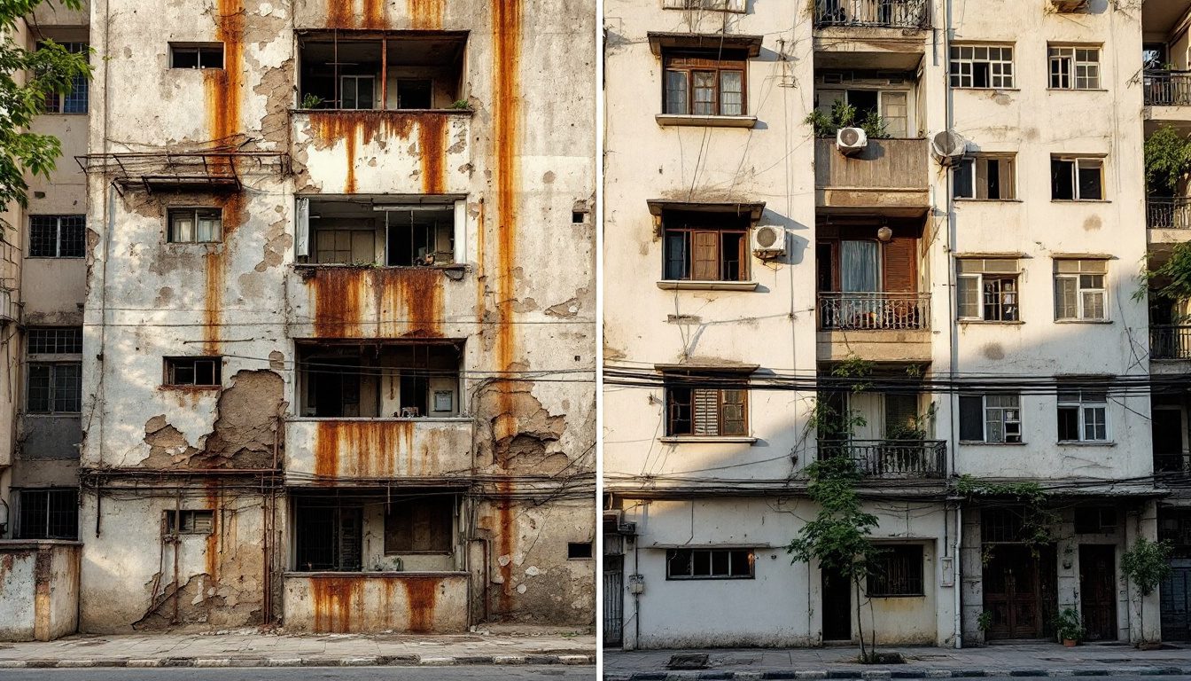
Two columns, same design loads. The one on the right will need structural repair in 10–15 years; the one on the left should remain passive for 40+ years. The difference is cover depth and mix quality.
6. Durability Levers in Design
Good durability starts on the drawing board, before a single bag of cement is opened.
Orientation and shading. A well-oriented house with deep chajjas (sunshades) over windows reduces direct solar exposure on walls, lowering thermal cycling stress and keeping surfaces drier in rain. Chajjas that project at least 600 mm over openings and have a downward-sloped outer edge with a drip groove prevent rain from sheeting down the wall below. This is not decoration; it is one of the cheapest durability investments possible.
Surface drainage and slope. Flat roofs must slope at least 1:100 (preferably 1:75) to drains. External paved areas must slope away from the building. Water that ponds on a flat roof is the single most reliable route to a leaking slab. Plinth protection aprons around the building should slope away at 1:10.
Expansion joints. Buildings and long walls expand and contract with temperature. Without planned joints, thermal forces create unplanned cracks — which then become water ingress routes. IS 456 recommends expansion joints at intervals of approximately 30 m in long structures in the Indian climate, though detailing depends on the specific geometry and exposure.
Material selection for the environment. Aluminium and uPVC window frames outperform timber in coastal and humid contexts because they do not rot, warp or corrode as readily as untreated wood. AAC (autoclaved aerated concrete) blocks have lower moisture absorption than poor-quality clay brick and better thermal performance in hot-dry climates. These are design choices with 30-year consequences.
Drip grooves and surface profiles. A small horizontal groove (kerf) on the underside of a chajja or coping stone breaks the surface tension of water running along the underside and causes it to drip off rather than run back onto the wall. This tiny detail — often omitted — accounts for a significant fraction of the staining and efflorescence seen on Indian buildings.
| Design lever | Durability benefit | Common failure to include |
|---|---|---|
| Deep chajja with drip groove | Keeps walls and junctions dry | Chajja too shallow; no drip groove |
| Roof slope to drains | Prevents ponding and slab saturation | Flat roof with no drain slope |
| Expansion joints at 30 m | Controls thermal crack pattern | Omitted to save cost |
| Appropriate exposure grade concrete | Resists corrosion for design life | Mild spec used in coastal zone |
| Material-climate match | Reduces rot/corrosion/thermal stress | Timber windows in coastal zone |
| Plinth height and protection apron | Keeps DPC above flood level | Low plinth in flood-prone areas |
7. Durability Levers in Construction
Design intent without construction quality is worthless. This is covered in depth in construction quality control for homeowners. The key durability levers at the construction stage are:
Curing — the cheapest multiplier. Concrete gains strength (and densifies its pore structure) through hydration — the chemical reaction between cement and water. Hydration requires moisture. If concrete is allowed to dry out quickly after casting — as happens routinely on Indian sites in summer — hydration stops prematurely. The surface layer remains porous, weak and susceptible to carbonation. Proper curing means keeping concrete continuously moist for a minimum of 7 days (14 days for OPC in hot weather, per IS 456). This costs almost nothing — water and hessian — but its absence costs enormously in accelerated decay.
Water-to-cement ratio control. Every bucket of water added beyond the design w/c ratio adds porosity. Site workers add water to make the concrete more workable; this is understandable on a hot afternoon but devastating for durability. Ready-mix concrete with a specified w/c ratio removes this temptation if the designer insists on it.
Cover maintenance. Rebar chairs and spacers must keep bars at their specified distances from the formwork. This is often ignored; bars are held by bits of stone or folded wire, which are unreliable. Plastic chairs cost a few rupees each. Without them, cover is random — often 10–15 mm where 40 mm was specified.
Compaction. Improperly vibrated concrete traps air voids and honeycombs that create direct penetration paths. Every pour should be vibrated systematically with a needle vibrator. Tapping the formwork is not a substitute.
Formwork stripping time. Stripping too early exposes immature concrete to drying and handling stress. IS 456 prescribes minimum striking times: typically 24–48 hours for soffit formwork of slabs, and 7–14 days for supporting formwork under beams.

Carbonation and chloride fronts advance at very different rates depending on concrete density and environment. In porous concrete near the coast, both fronts can reach the rebar in under a decade.
8. Material Service-Life Table
Different materials age at very different rates in Indian conditions. Understanding this is the foundation of specification choices that last.
| Material | Typical service life (Indian conditions) | Primary failure mode | Key durability variable |
|---|---|---|---|
| Well-made RCC (M25+, adequate cover, cured) | 50–75 years | Corrosion when cover depleted | w/c ratio, cover, curing |
| Poorly made RCC (M20, thin cover, uncured) | 15–25 years | Spalling, corrosion | Same variables — wrong values |
| Fired clay brick (good quality) | 75–100 years | Efflorescence, spalling in freeze-thaw | Firing quality, mortar |
| AAC block | 40–60 years | Plaster adhesion, surface erosion if uncoated | Surface coating, protection from water |
| Structural timber (treated, maintained) | 30–60 years | Rot, termite, UV in untreated sections | Treatment, ventilation, maintenance |
| Structural timber (untreated, humid zone) | 5–15 years | Rot and termite | No defence without treatment |
| External paint (quality acrylic, tropical) | 5–8 years | UV chalking, moisture blistering | UV resistance, surface prep |
| Waterproofing membrane (torch-applied) | 10–15 years | UV degradation at laps, traffic damage | UV protection, protective screed |
| Crystalline waterproofing (integral) | Typically 25+ years | Crack bridging limit | Crack width must stay within rated limit |
| Aluminium/uPVC windows | 20–40 years | Sealant failure, mechanism wear | Sealant quality, hardware grade |
| Timber windows (painted, maintained) | 15–25 years | Rot at sill, paint failure | Hardwood species, annual maintenance |
| Fired clay roof tiles (Mangalore) | 50–80 years | Ridge mortar failure, individual tile breakage | Mortar renewal every 15–20 years |
| Cement-fibre sheets (roofing) | 20–30 years | Asbestos-free grades slightly less durable | UV, foot traffic cracking |
9. Climate and Region — The Durability Risk Matrix
India's climatic diversity means durability risks vary dramatically by location. What works in Jaisalmer does not work in Kochi, and what works in Pune does not work in Shillong. Durability specifications must be calibrated to the actual environment.
For foundation durability risks in expansive soils, see foundation problems for homeowners. For seismic resilience (which intersects with durability in post-earthquake crack propagation), see earthquake zones and home design. For wind-induced cladding and façade durability, see wind loads on buildings.
| Climate zone | Primary durability risks | Specification priorities |
|---|---|---|
| Coastal — sea spray zone (within 1 km) | Chloride-driven corrosion, biological growth, cyclone impact | IS 456 severe/very severe, epoxy rebar, SRC, anti-algal paint |
| Coastal — marine air (1–10 km) | Moderate chloride risk, high humidity biological | IS 456 severe minimum, low w/c, quality coatings |
| Hot-humid (Kerala, Northeast, Andaman) | Biological growth, masonry moisture, timber rot | Drainage design, treated timber, anti-algal, vapour management |
| Hot-dry (Rajasthan, Gujarat interior) | Thermal cycling, dust, sulphate soils in places | Expansion joints, flexible sealants, SRC where sulphate risk |
| Composite/moderate (Delhi, UP plains) | Moderate corrosion, monsoon wetting-drying, hard water | IS 456 moderate, standard cover, quality waterproofing |
| Cold and highland (Himalayas, Nilgiris) | Freeze-thaw, moisture, reduced construction season | Air-entrained concrete, low absorption aggregates, heated curing |
| Expansive black-cotton soil regions | Foundation movement, sub-floor moisture | Under-slab DPC, controlled sub-grade, deep foundations |
"The environment does not just load the structure — it continuously modifies the material it is made of. A concrete designed for London will not perform the same way in Chennai." — Field observation cited in Indian concrete durability research literature

A drip groove costs almost nothing to form in shuttering. Its absence is responsible for a disproportionate share of the staining, efflorescence and surface decay on Indian residential buildings.
10. Maintenance as Designed Durability
The best-designed, best-built building will still decay faster without maintenance. Maintenance is not a sign that the building is failing — it is the act of keeping all the designed defence layers in working order.
Consider the logic of a paint film. The paint is not decoration; it is a moisture-excluding barrier. When it chalks, peels and cracks, the underlying plaster is exposed. Plaster absorbs moisture and passes it to the masonry. The masonry cycles wet and dry. Salts migrate. The paint fails for a further season. Now the masonry is etching. Five years of deferred paint represents ten to fifteen years of structural surface restoration work — at ten times the cost.
The same cascade applies to waterproofing membranes, sealant joints, roof drains, plinth protection, terrace tile grouting and window frame sealants. Each has a designed maintenance interval. Ignoring it does not defer the cost — it multiplies it.
| Maintenance task | Recommended frequency | Why it matters |
|---|---|---|
| External repainting (quality acrylic) | Every 5–7 years | Moisture barrier; delays carbonation and masonry saturation |
| Roof waterproofing inspection and re-sealing laps | Every 2 years; re-coat every 10 | Early detection of lap failures before slab saturation |
| Roof drain and parapet joint clearing | Before every monsoon | Blocked drains cause ponding; ponding causes leaks |
| Window sealant inspection and renewal | Every 3–5 years | Sealant failure is primary route for water at jambs |
| Plinth protection apron check | Every 3 years | Cracks allow water to sub-soak and undermine DPC |
| Retaining wall weep holes clearing | Annual | Blocked weeps build hydrostatic pressure → wall failure |
| External expansion joint sealant | Every 5–7 years | Sealant ages; open joints allow water ingress and widen |
| Structural crack monitoring | Annual — photograph and measure | Distinguishes stable hairline from progressing cracks |
| Terrace tile grouting and pointing | Every 7–10 years | Grout failure allows water under tiles to slab surface |
| Termite treatment (preventive) | Every 5 years, or per manufacturer | Subterranean termites operate silently; treatment is cheap |
"Deferred maintenance is a loan taken at compound interest from the structural fabric of the building." — As stated by structural engineers in condition assessment reports across Indian housing stock
The structural safety guide introduces the broader framework of what keeps a building standing. This guide is the companion that explains how to keep it standing for a lifetime.
11. Service Life — Maintained vs Neglected
The concept of a service-life curve makes the economics of durability intuitive. Imagine condition plotted on the vertical axis (100% on day one) and time on the horizontal. A maintained building loses condition slowly and predictably — major interventions are planned, not emergency. A neglected building loses condition gradually at first (invisible internal decay), then rapidly as multiple systems reach the end of their effective lives simultaneously.
The cost of rehabilitation at 30% condition is roughly 3–5 times the cost of the maintenance actions that would have kept it at 70% condition. This is not a rule of thumb; it is a consistent finding in building condition assessment practice across India and internationally.

The difference between the two curves represents years of livable life — and the gap in cost between the two paths is an order of magnitude.
12. Durability as Climate Action
There is one more dimension worth naming. The embodied carbon in a typical Indian residential building — the carbon emitted in manufacturing cement, steel, brick and glass — represents a significant fraction of the building's lifetime carbon footprint. If that building lasts 50 years, the embodied carbon is amortised over 50 years of use. If it lasts 20 years because of poor durability and then requires demolition and reconstruction, the embodied carbon is effectively doubled.
The most sustainable building is the one that lasts. Durability is not just an engineering preference; it is a climate responsibility. Specifying M25 over M20, requiring proper curing, maintaining the external envelope — these are decisions with consequences measured not just in years and rupees but in carbon.
For a homeowner commissioning a home that might house three generations, building for a 60-year service life is also the most economically rational choice when the cost is calculated over that full horizon, not just at handover.
Studio Matrx DesignAI can help homeowners think through material specifications and design choices that balance budget, aesthetics and this longer-horizon durability logic from the earliest stages of a project.
This guide is the capstone of the series — but the series itself is a toolkit. Structural design essentials covers the load-path foundations. What makes buildings crack covers diagnosis. Why buildings leak and waterproofing failures cover the envelope. Construction quality control covers the site execution. Foundation problems, earthquake zones and wind loads cover the forces and ground conditions. Together, they are the technical literacy a homeowner needs to commission, build and steward a home that lasts.
Author's Note
My father taught me that a building is a promise made to everyone who will ever live in it. You cannot be there for every monsoon it faces, every hot afternoon its walls absorb, every year its concrete quietly carbonates from the surface inward. But you can make choices — early, before the formwork goes up — that honour that promise. Cover depth. Curing days. Mix quality. Overhangs with drip grooves. These are not engineering abstractions. They are the difference between a building that your grandchildren inherit with pride and one they inherit as a liability. Durability science is the knowledge that bridges the gap. Carry it with you when you walk a site.
Disclaimer
This guide is intended for educational purposes — to build the technical vocabulary and conceptual understanding of homeowners, students and practitioners. It is not a substitute for a site-specific durability assessment, a licensed structural engineer's advice or compliance with applicable IS codes and local building regulations. Specific interventions — particularly for buildings showing active corrosion, spalling or structural distress — must be designed and supervised by a qualified professional.
References
1. Bureau of Indian Standards. IS 456:2000 — Plain and Reinforced Concrete — Code of Practice (Fourth Revision). BIS, New Delhi.
2. Bureau of Indian Standards. IS 13620:1993 — Fusion Bonded Epoxy Coated Reinforcing Bars — Specification. BIS, New Delhi.
3. Bureau of Indian Standards. IS 383:2016 — Coarse and Fine Aggregate for Concrete — Specification (Third Revision). BIS, New Delhi.
4. Bureau of Indian Standards. IS 1904:1986 — Code of Practice for Design and Construction of Foundations in Soils: General Requirements. BIS, New Delhi.
5. Bureau of Indian Standards. National Building Code of India 2016, Part 6 (Structural Design). BIS, New Delhi.
6. Mehta, P. K. and Monteiro, P. J. M. Concrete: Microstructure, Properties and Materials (4th edition). McGraw-Hill Education, 2014.
7. Neville, A. M. Properties of Concrete (5th edition). Pearson Education, 2011.
8. Gambhir, M. L. Concrete Technology: Theory and Practice (5th edition). McGraw-Hill Education India, 2013.
9. Pillai, S. U. and Menon, D. Reinforced Concrete Design (3rd edition). Tata McGraw-Hill, 2009.
10. fib (Fédération Internationale du Béton). Model Code for Service Life Design (fib Bulletin 34). International Federation for Structural Concrete, Lausanne, 2006.
11. Duggal, S. K. Earthquake Resistant Design of Structures (2nd edition). Oxford University Press India, 2013.
12. Bai, J. (ed.). Advanced Concrete Technology: Concrete Properties. Butterworth-Heinemann / Elsevier, 2003. (Includes chapters on durability mechanisms and chloride ingress modelling.)
13. Parrott, L. J. A Review of Carbonation in Reinforced Concrete. Cement and Concrete Association, Wexham Springs, 1987. (Widely cited baseline for carbonation rate data.)
14. Morinaga, S. "Prediction of Service Lives of Reinforced Concrete Buildings Based on Rate of Corrosion of Reinforcing Steel." Proceedings of the 5th International Conference on Durability of Building Materials and Components, Brighton, 1990.
15. Rajagopalan, N. Prestressed Concrete. Alpha Science International, 2005. (Cover requirements and durability in Indian practice.)
Word count: approximately 3,550 words.
Export this guide
Related Guides — Deep-dive reading
Best Window Material for Monsoon Regions (India): Beating Rain, Swell and Rust
For Kerala, the Konkan, the Northeast, the Western Ghats and Mumbai: which frame shrugs off driving rain, humidity, swelling and rust.
Windows & GlazingFoundation & Subsoil Drainage in India: French Drains, Weep Holes and Keeping Groundwater Off Foundations, Basements and Retaining Walls
A professional guide to subsoil drainage in India — French drains built from perforated pipe, gravel and geotextile; sub-surface drains around basements; weep holes and drainage board on retaining walls; and how you route the water you collect to a sump or soak pit. Plus the high-water-table and black-cotton-soil problems that make it hard, and why drainage and waterproofing are one system, not two.
PlumbingRoof Defects: A Homeowner's Field Guide (India)
The diagnostic catalog that anchors the whole subject — every common roof defect on Indian homes, pictured and named: cracks, damp and efflorescence, ponding, waterproofing blisters, sagging, spalling and rusting rebar, corrosion, algae and moss, parapet and drain-junction failures, slipped tiles and perished fasteners. For each: what it looks like, what it usually means, how serious it is, and exactly who to call.
RoofingRelated Tools — Try Free
Brise-Soleil Visualizer
Interactive horizontal-louvre cut-off angle calculator — sun altitude, louvre depth, and spacing inputs with a live shadow preview. Computes θ = arctan(spacing/depth) for façade shading, ECBC envelope compliance, hospital daylight design, and tropical sun-control detailing.
Sun Shading ToolCross-Ventilation Analyzer
Estimate airflow and air changes per hour (ACH) from room size, window areas, layout, and local wind — with NBC 2016 Part 8 compliance check.
Ventilation CalculatorMonsoon-Readiness Checklist
Pre-rain home audit across 9 categories — terrace, drains, waterproofing, electrical, HVAC, pest, vehicles, documents.
Seasonal Audit