
What Makes Buildings Crack? Reading the Cracks in Your Home
The homeowner's guide to cracks — why every building cracks a little, how to tell a harmless cosmetic crack from a dangerous structural one by its width, direction and pattern, and when to call an engineer.
Six months after moving into their new flat in Bengaluru, Kavitha noticed a thin line running diagonally from the upper corner of the bedroom window. It was barely visible — a hairline, perhaps the width of a strand of hair — but in the weeks that followed she could not stop looking at it. Was the building settling? Was the structure failing? Was she safe?
She called her civil engineer uncle. He came, looked for thirty seconds, and said: "That crack is textbook. Every building gets one of those. The sun heats the roof slab all day, it expands, it pushes the walls, the weakest point is the corner of an opening. Fill it, paint over it, sleep well."
Kavitha's anxiety is shared by almost every Indian homeowner. Cracks are the most visible, most alarming, and most misunderstood thing that happens to a building. This guide gives you the diagnostic literacy to read a crack the way a structural engineer does — to know when to reach for a tube of putty and when to reach for the phone.
A crack is a building relieving stress it cannot otherwise absorb; reading its width, direction, location, and whether it is growing tells you almost exactly what caused it.
1. Why All Buildings Crack a Little
There is no such thing as a perfectly stable solid material. Every material in a building expands, contracts, shrinks, creeps, and moves — continuously, through every season, through every monsoon, through every hot afternoon.
Concrete, when it sets, loses water and shrinks by roughly 0.02–0.06% of its length. A 10-metre slab therefore wants to pull itself inward by 2–6 mm. Plaster dries and shrinks similarly. A roof slab on a hot Indian afternoon might be 20–30°C warmer than at night; with a coefficient of thermal expansion of about 10–12 × 10⁻⁶ per °C, a 15-metre slab can expand by 3–5 mm in a single day. Over months and years, this back-and-forth movement accumulates.
Masonry walls do not move the same way as reinforced concrete slabs. Clay bricks expand slightly over their lifetime (moisture expansion). AAC blocks have different stiffness and thermal properties from the RCC frame they sit in. At every junction between dissimilar materials, movement is incompatible — and incompatible movement produces a crack.
Foundations move too. Soil consolidates under load. Black-cotton soil shrinks dramatically when it dries. A new building is still settling for 12–24 months after completion. In the vast majority of cases, this settlement is uniform and causes no harm. Only when settlement is uneven — one corner sinking faster than another — does it become a structural event.
"Buildings are not rigid bodies. They are assemblies of materials, each with its own thermal and mechanical life. Cracks are the record of that life."
— Field maxim among structural engineers, widely cited in diagnostic training literature
This is why almost every building develops some cracks in the first two years. Most are benign. The skill is in telling the difference.
2. A Taxonomy of Causes
Understanding what caused a crack is the only way to know whether it needs monitoring, cosmetic repair, or structural intervention. There are eight main cause categories.
2a. Drying Shrinkage and Plastic Shrinkage
Freshly placed concrete and plaster contain far more water than the chemistry needs. As this water evaporates during curing, the material contracts. If the contraction is restrained — by the existing structure, by reinforcement, by friction — tensile stress builds up. When that stress exceeds the tensile strength of the young material (which is low in the first 24–48 hours), a crack forms.
Plastic shrinkage cracks appear on horizontal surfaces (slabs, beams) within the first few hours of casting, before the concrete has set. They are typically shallow, random, and map-like. Drying-shrinkage cracks appear over days to months and are usually longer, straighter, and roughly perpendicular to the direction of restraint.
Poor curing — not keeping the concrete wet for the IS 456-prescribed minimum of seven days for ordinary Portland cement — greatly amplifies shrinkage cracking.
2b. Thermal Movement
The roof slab is the most thermally stressed element in any Indian building. Exposed to direct sun, it can reach 50°C+ on a summer afternoon while the walls below remain cooler. The differential expansion generates shear stress at the slab–wall interface. This is the single most common cause of the diagonal crack at the corner of the top-floor rooms — it is sometimes called the "top-floor thermal crack" or "classic expansion crack."
The same mechanism, at smaller scale, causes horizontal cracks along the bed-joints of the topmost course of masonry just below the roof beam, and occasional vertical cracks in the centre of long unreinforced walls without expansion joints.
2c. Differential Settlement and Foundation Movement
When a foundation settles unevenly — one column or footing sinking more than its neighbours — the superstructure is forced to deform. The deformation pattern produces characteristic crack geometries: diagonal cracks in the panel that is being distorted, stepped cracks along mortar joints in masonry, and sometimes vertical splits at re-entrant corners.
Settlement cracks are often wider at one end, tapering to a hairline at the other. The wide end points toward the zone that has sunk. They may continue to grow for months after construction. For a detailed look at foundation causes and remedies, see the companion guide foundation problems for homeowners.
2d. Structural Overload and Deflection
When a beam or slab deflects more than it should — because it is overloaded, undersized, or the reinforcement is insufficient — it cracks in characteristic ways. Beams crack at the bottom in the mid-span zone (flexural cracks, roughly vertical, widest at the soffit). Under shear overload near supports, diagonal cracks form at roughly 45°. Slabs crack on the tension face, which for a simply supported slab is the underside.
Horizontal cracks in columns are especially serious — they indicate that the column may be in bending or eccentric compression and needs immediate engineering attention.
2e. Moisture, Dampness, and Rebar Corrosion
Reinforcing steel that corrodes increases in volume by up to 6–10 times the original steel volume. This expansion from within the concrete cover exerts enormous outward pressure and causes a very characteristic type of damage: longitudinal cracks running parallel to the reinforcement, often accompanied by rust staining (brown-orange streaks running down the face), and eventually spalling — chunks of concrete popping off to expose the rusting bar.
This is one of the most serious crack types in Indian coastal and high-humidity environments because it is self-accelerating: the crack allows more moisture in, which accelerates corrosion, which widens the crack further. Why buildings leak and waterproofing failures cover the moisture entry pathways that initiate this cycle.
2f. Chemical Deterioration
Sulphate attack occurs when sulphates in soil or groundwater react with constituents of cement paste, causing expansion and progressive cracking — often with a distinctive white efflorescence and a soft, sugary texture to the concrete. Alkali-silica reaction (ASR) between reactive silica in certain aggregates and alkalis in cement creates an expanding gel that produces map-cracking ("crazing") across large areas. These are slow, long-term processes but ultimately destructive.
2g. Dissimilar Material Junctions
RCC frames and masonry infill walls move differently. Over years of thermal cycling, the junction between the concrete column or beam and the brick or AAC-block infill becomes a predictable crack location — a clean vertical or near-vertical crack exactly at the interface. Similarly, at doorframes and window frames where different materials meet, hairline cracks are almost universal and almost always benign.
2h. Vegetation, Vibration, and Seismic Events
Tree roots exert significant pressure as they grow, can lift footings and crack walls and floors. Construction vibration from nearby pile-driving, blasting, or heavy traffic can loosen mortar joints and propagate existing microcracks. An earthquake imposes abrupt differential displacement; post-seismic crack surveys follow the same diagnostic logic but at larger scale, and IS 4326 and IS 13920 govern the design provisions meant to limit such damage.
3. Reading a Crack: The Diagnostic Framework
A crack communicates information through five variables: width, direction, location, pattern, and whether it is growing.
Crack Width Classification
The BRE (Building Research Establishment) Digest 251, widely referenced in Indian practice alongside IS 456 provisions, provides a practical classification:
| Category | Approximate Width | Description | Typical Action |
|---|---|---|---|
| 0 — Hairline | Less than 0.1 mm | Invisible except on close inspection | Monitor; no treatment needed |
| 1 — Very slight | 0.1–1 mm | Fine cracks; width of a card edge | Cosmetic filler; monitor |
| 2 — Slight | 1–5 mm | Easily seen; may admit slight dampness | Rake out and repoint; investigate cause |
| 3 — Moderate | 5–15 mm | Requires opening up; possible serviceability issue | Engineering appraisal needed |
| 4 — Severe | 15–25 mm | Requires structural repair | Structural engineer required urgently |
| 5 — Very severe | Over 25 mm | Structural stability in question | Immediate evacuation assessment |
Note: IS 456 Clause 35.3 limits permissible crack width in reinforced concrete to 0.3 mm for mild exposure and 0.2 mm for moderate/severe exposure — these are design limits for new construction, not field crack thresholds.
The Crack-Reading Matrix
| Direction | Location | Likely Cause | Severity Indication |
|---|---|---|---|
| Diagonal from opening corner (45°) | Top-floor wall near window/door | Thermal movement of roof slab | Usually cosmetic; monitor first season |
| Diagonal (stepped in masonry) | Panel between columns/walls | Differential settlement | Moderate; needs monitoring and possible engineering check |
| Vertical | Mid-span of long unreinforced wall | Drying shrinkage or thermal | Usually cosmetic |
| Vertical, at RCC–masonry junction | Exactly at column/beam edge | Differential movement, dissimilar materials | Cosmetic; seal with flexible filler |
| Horizontal | Mid-height of column or beam | Bending, buckling, or shear (overload) | SERIOUS — engineer now |
| Diagonal at 45° near beam end | Beam near support (soffit or web) | Shear overstress | SERIOUS — engineer now |
| Map/random (crazing) | Large wall or slab face | Shrinkage crazing, ASR, sulphate attack | Usually superficial; investigate if widening |
| Longitudinal, with rust stains | Parallel to reinforcement | Rebar corrosion and concrete spalling | SERIOUS — engineer required |
| Near plinth, wider at top | Lower floor corner or wall base | Foundation settlement | Moderate to serious — monitor and investigate |
4. Cosmetic vs Structural: The Key Distinction
This is the question that matters most. The table below summarises the principal distinguishing features:
| Feature | Cosmetic Crack | Structural Crack |
|---|---|---|
| Width | Under 1 mm (hairline to fine) | Often over 5 mm; or narrower but growing |
| Depth | Surface plaster or render only | Passes through the structural element |
| Location | Infill wall, plaster finish, junction | Beam, column, load-bearing wall, slab soffit |
| Direction | Diagonal at openings, vertical at junctions, map-crazing | Horizontal in columns/beams; diagonal widening in panels |
| Movement | Dormant (stable; same width over months) | Active (growing; or open-close with seasons) |
| Associated signs | None | Rust staining, spalling, sagging, door/window jamming |
| Cause | Shrinkage, thermal, dissimilar materials | Overload, corrosion, foundation failure |
| Remedy | Fill, seal, repaint | Engineering diagnosis, repair of cause, then structural fix |

The six most common crack patterns and their typical causes — direction and location together give the diagnosis.
5. How to Diagnose at Home
You do not need an engineering degree to conduct a useful preliminary assessment. The following steps give you the information you need before calling a professional, and help the engineer help you.
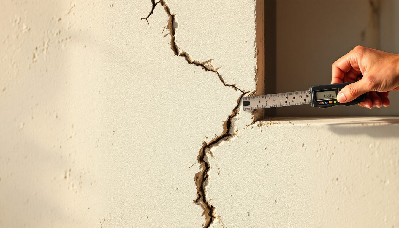
Step 1: Measure the Width
A standard Rs. 5 coin is about 1.9 mm thick; a credit card is about 0.76 mm; a human hair is 0.05–0.07 mm. Slide these against the crack to get a rough category. If you want better precision, a plastic crack gauge (available at hardware and surveying suppliers for under ₹300) has graduated slots from 0.1 mm upward.
Step 2: Assess the Depth
Using a knife or a stiff piece of card, probe gently whether the crack is surface-only (plaster) or goes deeper. If you can probe beyond the plaster into the substrate, it has penetrated the masonry or concrete. A through-wall crack — where you can feel air movement with a damp hand — is a more serious finding.
Step 3: Monitor Whether It Is Growing
This is the most important diagnostic step. An active crack requires urgent investigation; a dormant crack can usually be repaired at your convenience.
The simplest monitoring method: use a pencil to mark the ends of the crack on both sides with a small line perpendicular to the crack, and note the date. A more reliable method is to bridge the crack with a tell-tale — a rigid transparent plastic strip or a plaster button fixed across the crack; any movement causes the tell-tale to break or shift. Commercial crack monitors (available from ₹150–600 each) have a dual-scale grid that shows both opening/closing and lateral shear.
Monitor at two-week intervals for the first month, then monthly. Photograph under the same lighting conditions each time.

Use this decision tree before reaching for filler — the two paths require very different responses.
Step 4: Note Associated Symptoms
- Are nearby doors or windows sticking, twisting, or no longer closing squarely? This suggests the structural frame is distorting.
- Is there rust staining running down the wall surface from the crack?
- Can you see concrete spalling (chunks breaking away) exposing steel?
- Is the floor in the room noticeably uneven or sloping where it was not before?
- Did the crack appear suddenly (overnight, or following an event like a construction blast, heavy rain, or a tremor)?
Any of these converts a crack of any width from a possible cosmetic issue to a probable structural event.
The Monitoring Method: Step by Step
| Step | What to Do | When |
|---|---|---|
| 1 — Mark ends | Draw perpendicular pencil lines at both ends of the crack; write the date | Day 1 |
| 2 — Measure width | Use a crack gauge or coin equivalents; note the measurement | Day 1 |
| 3 — Photograph | Photo in consistent lighting, with a ruler in frame | Day 1 |
| 4 — Check | Compare marks and width to original | Week 2 |
| 5 — Re-photograph | Under the same conditions | Week 2 |
| 6 — Continue | Monthly thereafter; note any seasonal pattern (wider in summer heat?) | Monthly |
| 7 — Decide | Dormant for 3 months with no growth: cosmetic repair | At 3 months |
| 7 — Escalate | Any growth at any re-check, or association with structural symptoms | Immediately |

Monitoring costs nothing but attention; it is the difference between catching a slow structural problem early and discovering it catastrophically late.
6. Danger Signs: Call a Structural Engineer Now
The following signs require professional assessment without delay. Do not wait, do not fill the crack, do not repaint. Get an engineer on site.
| Danger Sign | What It May Indicate |
|---|---|
| Horizontal cracks in a beam or column | Bending overstress, possibly structural failure progressing |
| Any crack with rust staining or spalling | Rebar corrosion — self-accelerating, eventually causes collapse of cover and section loss |
| Diagonal cracks that are actively widening | Progressive settlement or structural distortion |
| Cracks accompanied by doors/windows jamming or twisting | Frame distortion — the building's geometry is changing |
| Crack with visible sag in a beam or slab | Deflection beyond serviceability; structural capacity possibly exceeded |
| Multiple new cracks appearing quickly | Sudden load or progressive failure; cause must be identified |
| Any crack after an earthquake, however thin | Seismic damage may have reduced residual capacity even if the crack looks benign |
| Crack in a load-bearing wall (especially if horizontal) | Load path may be compromised |
| Soft or powdery concrete adjacent to a crack | Sulphate attack or chemical deterioration — the concrete may be losing strength |
"A crack that is growing tells a story you must not ignore. The question is never 'is this crack serious?' but 'is this crack moving?' — and only monitoring, not appearance alone, can answer that."
— S. K. Duggal, Earthquake Resistant Design of Structures, widely cited field guidance
7. Common Indian Crack Scenarios
Understanding the common patterns reduces anxiety and sharpens diagnosis. The broad guide to structural safety situates these within the full safety picture.
The Top-Floor Thermal Crack
This is India's single most common complaint. The exposed roof slab heats up by 20–30°C during a summer day and forces the top of the supporting walls outward. The wall panel resists this push through its corners, and the weakest zone — the corner of a door or window opening — cracks diagonally at 45°. These cracks widen in summer, close slightly in winter. They are almost always in the plaster and upper masonry only, not structural. An expansion joint between the roof slab and the parapet or top wall course, if properly designed, prevents this; in its absence, an annual fill with a flexible (non-rigid) sealant is the appropriate response.

The top-floor thermal crack is one of the most common, most alarming, and least dangerous cracks in Indian buildings — caused by the slab expanding in the sun.
RCC–Brick Junction Cracks
In a reinforced concrete frame building, the brick or AAC infill walls are non-structural — they carry no vertical load. But they are bonded to the frame at their edges. When the concrete column and the brick wall expand and contract differently through the seasons, a clean vertical crack forms exactly at the junction. This is cosmetic. It should be sealed with a flexible polyurethane sealant rather than a rigid cement filler, since the movement will continue.
Plaster Map-Crazing
A fine network of interconnected cracks covering a large area of a plastered wall is called crazing or map-cracking. It is almost always a plaster problem — too much water in the mix, too-thin application, or application in direct sunlight that dried the surface too fast. It does not indicate structural distress. Scraping off and replastering correctly resolves it.
Corner-of-Opening Diagonal
As described under thermal movement — hairline diagonal cracks at window and door corners are the most commonly misdiagnosed crack type. Their presence does not indicate foundation problems or structural failure. Monitor for growth; if stable for one full seasonal cycle, fill and repaint.
Plinth and Settlement Cracks
Cracks appearing at plinth level (the transition between foundation and superstructure) or that are wider at the top and taper downward often indicate differential settlement — one part of the foundation has settled more than another. These warrant investigation. On expansive soils (black-cotton soil in the Deccan plateau and parts of Maharashtra, Andhra Pradesh, Karnataka), seasonal heave and shrinkage of the soil can cause seasonal cracking that opens in dry months and closes in the monsoon. Foundation problems for homeowners covers this in full.
External Wall Map-Cracking with Damp Staining
Large, irregular cracks on external faces accompanied by damp penetration are typically moisture-linked. Water entering through the crack degrades the plaster and potentially the masonry behind it. Left unattended, the moisture reaches the reinforcement and initiates corrosion. This is the entry point of the dampness→corrosion→spalling cycle covered in detail in why buildings leak.

Settlement cracks have characteristic geometries depending on which part of the foundation has moved — the wide end of the crack points toward the sinking zone.
8. Cause, Appearance, and the Fix
It is worth mapping causes to the repairs they require — because applying the wrong repair to the wrong crack is not merely useless but can be actively harmful. Filling a structural crack with rigid mortar creates a new stress concentration; the original crack reopens, or a new crack forms adjacent to the now-rigid repair.
| Cause | Typical Appearance | Cosmetic or Structural | Appropriate Response |
|---|---|---|---|
| Thermal (roof slab expansion) | 45° diagonal at window corners, top floor | Cosmetic | Monitor; flexible polyurethane sealant seasonally |
| Drying shrinkage (plaster) | Map-crazing, random fine network | Cosmetic | Rake off defective plaster, replaster correctly |
| RCC–masonry junction movement | Clean vertical crack at column face | Cosmetic | Flexible sealant; do not use rigid cement |
| Foundation differential settlement | Stepped, diagonal, wider at one end | Potentially structural | Monitor; structural engineer appraisal if growing |
| Beam flexural overstress | Vertical cracks at mid-span soffit, opening downward | Structural | Engineer now; do not load further |
| Rebar corrosion | Longitudinal, with rust staining and spalling | Structural | Engineer now; carbonation/chloride tests |
| Shear failure near support | 45° diagonal near beam ends | Structural | Engineer now; possibly evacuate |
| Sulphate attack | Map-cracking with white efflorescence, soft concrete | Structural | Engineer now; chemical analysis |
| Seismic damage | X-cracks in panels, diagonal in infill | Potentially structural | Post-quake inspection protocol; engineer |
9. Repair Approaches — Diagnose First
The principle is simple: you must treat the cause, not just the symptom. A crack that is filled without treating its cause will reopen, often wider.
Cosmetic cracks (stable, hairline to 1 mm, in plaster, non-structural): rake out the crack to clean edges using a cold chisel, blow out dust, prime, and fill with a polymer-modified cement filler or an appropriate flexible sealant. Repaint when cured.
Serviceability cracks in masonry (2–5 mm, stable, in non-load-bearing walls): repoint with a 1:1:6 cement-lime-sand mortar; lime adds a degree of flexibility. Investigate the cause of movement before repointing.
Structural repairs are outside the scope of DIY and require a structural engineer's specification. The broad toolkit includes:
- Crack stitching: stainless-steel helical bars grouted across the crack plane in masonry, restoring tensile capacity without rigidly bridging the crack
- Epoxy injection: for non-active structural cracks in concrete, epoxy resin is pressure-injected to restore monolithic behaviour and close the crack path to moisture
- Grouting: for voids behind masonry or in rubble-stone walls
- Underpinning: for foundation settlement — micro-pile underpinning or mass concrete underpinning to stabilise a footing that has moved
- Expansion joints: inserted where movement is expected, allowing controlled relative motion without uncontrolled cracking; should have been designed in from the start
"The golden rule of crack repair: diagnosis before mortar. A crack tells you something is wrong somewhere in the building's load path or material life. Fill it without understanding it and you have merely silenced the alarm."
— Matthys Levy and Mario Salvadori, Why Buildings Fall Down (W.W. Norton, 1992)
10. Prevention: Building Right from the Start
Most cracks are preventable. The measures are straightforward; their omission is almost always a result of cutting corners on site. Construction quality control for homeowners gives you a full site inspection framework; the crack-specific imperatives are:
Curing: IS 456 Clause 13.5 requires a minimum curing period of seven days for ordinary Portland cement in moderate exposure conditions. On site, this is the most commonly compromised requirement. Under-cured concrete shrinks more, develops lower early strength, and cracks more readily. Wet curing with hessian sacking, curing compounds, or ponding are all acceptable if consistently maintained.
Control joints and expansion joints: In long walls, roofs, and slabs, IS 456 and the NBC 2016 recommend spacing of expansion joints based on temperature variation and material. Roof slabs should have a slip layer (two layers of polythene sheeting) between the slab soffit and the supporting walls, or purpose-designed expansion joints, to allow thermal movement without imposing stress on the walls below.
Good detailing at junctions: RCC-masonry junctions should be detailed with a movement allowance — a pre-formed strip of compressible foam or a scripted-and-sealed joint rather than a rigid bond.
Concrete quality: Using the correct water-cement ratio (typically 0.45–0.55 for M20/M25 as designed), not adding water on site for workability, using admixtures if needed, and avoiding over-vibration all reduce shrinkage cracking.
Drainage and damp proofing: A damp-proof course at plinth level, correct external grading, and functioning drains keep moisture away from foundations and walls — preventing the ingress that initiates corrosion and sulphate attack.
For a broader view of how materials and detailing decisions interact with long-term durability, the guide on the science behind durable buildings is the companion read.
"Shrinkage cracks in concrete are not failures of the material — they are failures of process. Every one of them could have been prevented by adequate curing, proper mix design, or appropriate joint spacing."
— M. L. Gambhir, Concrete Technology, 5th ed. (McGraw-Hill, 2013)
Where you are still in design or early construction, Studio Matrx DesignAI can help you review your plans and highlight detailing risks before the slab is poured.
11. Quick-Reference Summary
| Question | Short Answer |
|---|---|
| Is a hairline crack at a window corner dangerous? | Almost always no — classic thermal crack; monitor for one season |
| What width should trigger engineering appraisal? | Over 5 mm, or any width that is actively growing |
| Are horizontal cracks in a beam serious? | Yes — call a structural engineer immediately |
| Can I fill and repaint a structural crack? | No — treating the symptom masks the cause and is dangerous |
| How long should I monitor before I repair? | Minimum one full seasonal cycle (summer to monsoon to winter), 3 months minimum |
| What is the worst type of crack? | Longitudinal with rust staining/spalling — rebar corrosion is self-accelerating |
| Is a crack after an earthquake always serious? | It needs professional assessment — it may be minor, but seismic damage reduces residual capacity |
Author's Note
Every time a client called my father in panic about a crack, he would say: "Bring me to see it before you worry." Nine times out of ten the fear dissolved in thirty seconds. The tenth time, his calmness was replaced by a deliberate seriousness — and his early recognition made the difference between a fixable problem and a catastrophe.
Diagnostic literacy is one of the most empowering things a homeowner can have. You do not need to be an engineer to read a crack intelligently — you need to know where to look, what questions to ask, and when to hand it to an expert. The cracks are the building speaking. This guide teaches you the language.
Disclaimer
This article is for educational purposes only and does not constitute a structural or engineering assessment. Crack identification and repair in any building requires an on-site evaluation by a licensed structural or civil engineer. No guidance in this article should be used as a substitute for professional site inspection. If you observe any of the danger signs listed in Section 6, consult a qualified structural engineer before taking any other action.
References
1. Bureau of Indian Standards. IS 456:2000 — Plain and Reinforced Concrete: Code of Practice, 4th revision. BIS, New Delhi, 2000. Clause 13.5 (curing), Clause 35.3 (permissible crack widths).
2. Bureau of Indian Standards. IS 1893 (Part 1):2016 — Criteria for Earthquake Resistant Design of Structures. BIS, New Delhi, 2016.
3. Bureau of Indian Standards. IS 4326:2013 — Earthquake Resistant Design and Construction of Buildings: Code of Practice. BIS, New Delhi, 2013.
4. Bureau of Indian Standards. IS 1904:1986 — Code of Practice for Design and Construction of Foundations in Soils: General Requirements. BIS, New Delhi, 1986.
5. Ministry of Housing and Urban Affairs. National Building Code of India 2016, Volume 1 and 2. BIS, New Delhi, 2016.
6. Building Research Establishment. BRE Digest 251 — Assessment of Damage in Low-Rise Buildings. BRE Press, Watford, UK, 1981 (updated guidance used internationally for crack classification).
7. Ransom, W. H. Building Failures: Diagnosis and Avoidance, 2nd ed. E & F N Spon, London, 1987.
8. Levy, Matthys, and Mario Salvadori. Why Buildings Fall Down: How Structures Fail. W. W. Norton & Company, New York, 1992.
9. Salvadori, Mario. Why Buildings Stand Up: The Strength of Architecture. W. W. Norton & Company, New York, 1980.
10. Gambhir, M. L. Concrete Technology: Theory and Practice, 5th ed. McGraw-Hill Education (India), New Delhi, 2013.
11. Pillai, S. Unnikrishna, and Devdas Menon. Reinforced Concrete Design, 3rd ed. Tata McGraw-Hill, New Delhi, 2009.
12. Duggal, S. K. Earthquake Resistant Design of Structures, 2nd ed. Oxford University Press, New Delhi, 2013.
13. Neville, A. M. Properties of Concrete, 5th ed. Pearson Education, Harlow, UK, 2011. (Authoritative reference on concrete shrinkage, creep, and crack formation.)
14. Allen, Edward, and Joseph Iano. Fundamentals of Building Construction: Materials and Methods, 6th ed. Wiley, Hoboken, NJ, 2013.
15. Tomlinson, M. J., and R. Boorman. Foundation Design and Construction, 7th ed. Pearson Education, Harlow, UK, 2001.
Export this guide
Related Guides — Deep-dive reading
Cracks in Your Roof & Slab: What They Mean and When to Worry
Not every crack is a crisis, and not every crack is harmless. A calm, India-grounded field guide to reading cracks on RCC roofs, terraces, parapets and ceiling plaster — hairline vs map vs structural, what each type means for leaks and for the structure, the safe homeowner job of observe-photograph-measure-monitor, and the exact patterns that mean call a structural engineer today.
RoofingFoundation Problems Every Homeowner Should Understand
What lies beneath the house — foundation types, the problem soils of India, black-cotton heave and differential settlement, the warning signs of foundation movement, and the soil test that prevents lakhs in damage.
Structural SafetyRoof Defects: A Homeowner's Field Guide (India)
The diagnostic catalog that anchors the whole subject — every common roof defect on Indian homes, pictured and named: cracks, damp and efflorescence, ponding, waterproofing blisters, sagging, spalling and rusting rebar, corrosion, algae and moss, parapet and drain-junction failures, slipped tiles and perished fasteners. For each: what it looks like, what it usually means, how serious it is, and exactly who to call.
RoofingRelated Tools — Try Free
Cross-Ventilation Analyzer
Estimate airflow and air changes per hour (ACH) from room size, window areas, layout, and local wind — with NBC 2016 Part 8 compliance check.
Ventilation CalculatorMonsoon-Readiness Checklist
Pre-rain home audit across 9 categories — terrace, drains, waterproofing, electrical, HVAC, pest, vehicles, documents.
Seasonal AuditBefore & After Studio
Generate AI before-and-after renders to preview how your redesign could look.
DesignAI