

HVAC Drawings Explained
Cooling, heating and fresh air on paper — how to read indoor and outdoor unit positions, refrigerant and drain routes, ducts and diffusers, the reflected ceiling plan, and ventilation.
The contractor unrolls a sheet you have not seen before. There are no walls full of bricks on it, no steel bars, no taps. Instead there are little boxes on the walls of every bedroom, a fat dotted line snaking through the ceiling, and rows of squares with diagonal crosses inside them. "AC and ventilation," he says, and rolls it back up. You nod as if you understood.
You did not, and that is completely normal. This is the one set of drawings most homeowners never really learn to read — and the one that, if ignored until the false ceiling is up, becomes the most expensive to fix. A misplaced outdoor unit, a drain pipe with no fall, a return-air path nobody planned — these are not catastrophes you can see. They are decisions hidden inside this sheet.
Let us slow down and read it together.
An HVAC drawing is the plan that shows how a building is cooled, warmed and supplied with fresh air — where every indoor and outdoor unit sits, how refrigerant and condensate-water travel between them, and how conditioned air is pushed into and pulled back out of each room.
This guide is written first for the homeowner holding the sheet, and then — once each idea is clear — taken to the depth a B.Arch or civil student and a junior site engineer actually need. HVAC (Heating, Ventilation & Air-Conditioning) is the last of the big building services, so read it after plumbing and electrical; see how all the services stack in how construction drawings work together, and keep the masterclass pillar open as your map.
If you cannot see where the water and the warm air leave the room, the system is not finished on paper — only on the salesman's brochure.
1. The two families: split and ducted (and VRF in between)
Almost every Indian home cools itself with one of two arrangements, and the drawing looks quite different for each.
A split AC splits the machine into two halves. The indoor unit — the slim box high on a bedroom wall — does the cooling you feel. The outdoor unit — the noisy metal box on the ledge or terrace — throws the collected heat outside. They are joined by a pair of thin copper pipes (the refrigerant) and a small drain pipe. One indoor unit, one outdoor unit, one room. Simple, cheap, and by far the most common system in India.
A ducted system hides a single larger indoor unit above the false ceiling. From it, a tree of insulated ducts carries cooled air across the ceiling and drops it into several rooms through ceiling outlets. You see no wall box anywhere — only neat squares in the ceiling. It cools evenly and silently but costs more and eats ceiling height.
Between them sits VRF / VRV (Variable Refrigerant Flow / Volume — the same technology, VRV being Daikin's trademarked name). Here many indoor units share one large outdoor unit through a network of refrigerant pipes, each room controlled independently. It is the premium choice for larger homes and apartments.

| System | What you see on the drawing | Where it fits | Trade-off |
|---|---|---|---|
| Wall split | One indoor box per room + one outdoor box each | Most Indian homes, room-by-room | Cheapest; many outdoor units to place |
| Cassette / ducted split | Concealed unit + ducts + ceiling outlets | Living/dining, open plans | Even & silent; needs ceiling depth |
| VRF / VRV | Many indoor units, few large outdoor units, refrigerant network | Larger homes, apartments | Flexible & efficient; highest cost |
For students & site engineers: the drawing set typically separates into a layout plan (units, pipe runs, duct routes), a schematic / riser (how outdoor units stack and connect vertically), and schedules (unit-by-unit capacity, airflow in CFM, drain and pipe sizes). Capacity is shown in TR (tons of refrigeration) — one ton being roughly the cooling of melting a ton of ice per day. A common Indian rule of thumb is loosely "about one ton per 100 to 150 sq ft" of room, but treat that only as a sanity check — the stamped drawing should carry a proper heat-load calculation (orientation, glazing, occupancy, climate zone) per ISHRAE design data. Values here are indicative.
2. Reading the reflected ceiling plan (RCP)
Here is the single idea that unlocks half of an HVAC sheet. Most HVAC outlets and almost all light fittings are not on the floor plan at all — they are on the reflected ceiling plan.
Picture lying on your back on the floor and looking straight up at the ceiling. Now imagine, instead, a giant mirror laid flat on the floor reflecting that ceiling. The RCP draws what you would see in that mirror — the ceiling, but flipped so that left stays left and you can lay it beside the floor plan without your head spinning. That is why diffusers, grilles, light points and ceiling access panels all live on the RCP.

On the RCP you will meet four recurring symbols. Learn these four and the ceiling stops being a mystery.
| Symbol on RCP | What it is | What it does |
|---|---|---|
| Square/round with diagonal crosses | Supply diffuser | Pushes cooled air INTO the room, spread in 1 / 2 / 4 directions |
| Plain louvred rectangle | Return-air grille | Pulls room air BACK to the unit to be re-cooled |
| Small louvred square near wall | Exhaust / fresh-air grille | Throws stale air out, or draws fresh air in |
| Hatched rectangle | Access panel | A removable ceiling hatch to service the hidden unit, filter or damper |
A practical homeowner test: the squares with the diagonal pattern are supply (air blows toward you — hold a tissue and it flutters away); the plainer one is return (the tissue is sucked toward it). The arrows or pattern inside a diffuser tell you which way it blows — a corner unit usually gets a 2-way, a room-centre unit a 4-way.
Red flag: if the RCP shows lovely supply diffusers in a sealed room but no return path — no return grille and no door undercut — the air has nowhere to go back. The room will be noisy, stuffy and under-cooled. A supply with no return is a half-drawn system.
For students & site engineers: because the RCP is drawn to register with the floor plan — same orientation, left-right and top-bottom both matching, so the two sheets can be overlaid — north and the column grid must align exactly with the floor plan — always confirm the diffuser layout against the structural beam grid and the lighting RCP, because diffusers, light fittings and a return grille all compete for the same ceiling and frequently clash. Coordinate before the framing of the false ceiling is closed.
3. The two routes nobody should leave to the last minute
Every indoor unit, split or ducted, has two lines leaving it that decide whether the system is a pleasure or a permanent headache: the condensate drain and the refrigerant pair-pipe. Both must be planned while the slab and walls are still open.

The condensate drain — it runs on gravity alone
As the indoor unit cools, water condenses on its coil — litres of it on a humid Mumbai afternoon. That water must drain downhill, every inch of the way, with no pump and no luck involved. On the drawing the drain line is shown with a continuous fall toward a discharge point — a floor trap, a balcony, a rainwater pipe. Standard practice keeps a minimum slope of about 1 in 100 (one percent), and many engineers draw a more comfortable fall where they can; the exact figure is indicative and must come from your stamped drawing.
Red flag: a drain line that runs flat, or worse, dips and rises, will pool, breed slime, block, and one day drip brown water through your new false ceiling. If you cannot trace a continuous downhill path from every indoor unit to a drain on the plan, ask before the ceiling closes.
The refrigerant pair-pipe — keep the two units close
The indoor and outdoor units are joined by two insulated copper pipes — a thicker suction line and a thinner liquid line — drawn together as a pair, usually as a chained or dashed line with its own legend symbol. They pass through the wall in a sleeve (a pipe cast into the wall so you never break finished masonry later). The drawing also fixes how far apart and how high apart the two units sit, because longer and taller runs lose efficiency and need more refrigerant. Keep the units as close as the layout honestly allows.
| Service line | Drawn as | Governed by |
|---|---|---|
| Condensate drain | Continuous line with slope/fall | Gravity; min ~1 in 100 (indicative) |
| Refrigerant suction (thick) + liquid (thin) | Paired chained/dashed line, on legend | Pipe length & height limits per manufacturer |
| Wall sleeve | Small circle / sleeve note at wall | Cast-in before finishing |
Put the two routes together and a split system reads as one simple schematic: refrigerant crosses the wall through a sleeve as a thick suction line and a thin liquid line to the outdoor condenser, while the condensate drain leaves the same indoor unit and falls all the way to a discharge point — two lines out, both planned before the wall closes.

4. Ducts, supply & return — why you always need both
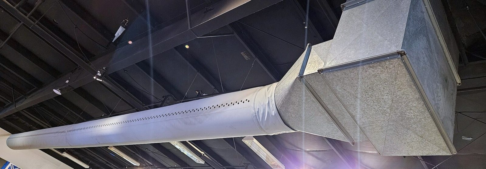
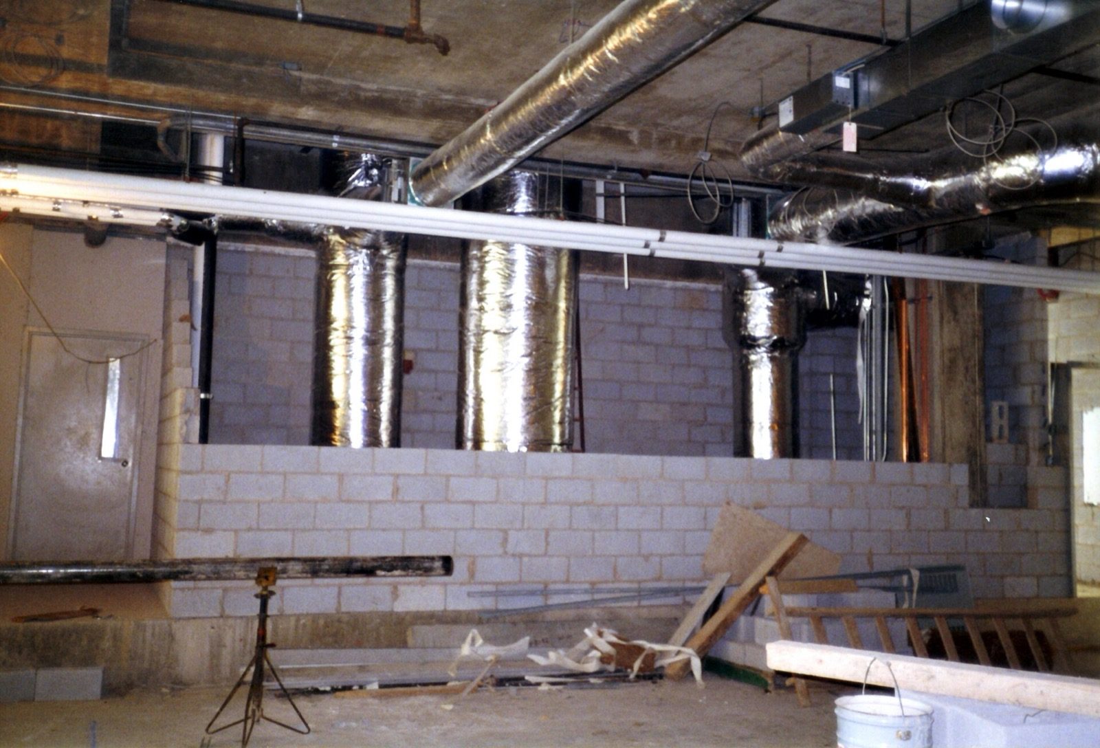
In a ducted or VRF home the conditioned air travels through ducts — usually rectangular galvanised sheet or insulated boxes — shown on the plan as wide double-line channels with their size noted (for example 300 x 200, in mm, width by depth). Watch their depth: a deep duct crossing under a beam can swallow your ceiling height, so duct routes must be coordinated with the beam layout early.
But a duct that only delivers air is half a system. Air pushed in must be allowed back out, or the room simply pressurises and stops accepting more. So every conditioned space needs two openings: a supply that delivers cooled air and a return that carries room air back to the unit to be filtered and re-cooled.

Picture the air as a loop, not a one-way blast: it leaves the diffuser cool, sinks, sweeps the room, warms a little, and is pulled back through the return grille to start again. Break the loop and the room never settles. Where a separate return grille is not provided, a deliberate door undercut (a small gap under the door) is sometimes the planned return path — but that is a decision, not an accident, and it should be visible in the design intent.
Zoom out from the single room to the whole floor and the same loop should be legible across the plan: one concealed indoor unit feeds a branching supply tree to a diffuser in every room, and a single shared return grille in the central hall draws all that air back — with bedroom doors carrying an undercut so a closed door never starves a room.

On site, those flat lines on the plan become real metal above the ceiling. The duct tree is usually fabricated in galvanised sheet steel — straight rectangular trunks branching into round insulated runs that feed each diffuser — exactly the kind of run that must be coordinated with the beams before the false ceiling closes.
Then there is plain ventilation — fresh air and exhaust, separate from cooling. Toilets, kitchens and any deep interior room need an exhaust path to throw stale, humid or smoky air out. NBC 2016 Part 8 Building Services, Section 3 (Air-conditioning, Heating & Mechanical Ventilation) frames residential fresh-air needs in the order of roughly 20 to 30 cubic metres per person per hour; the exact rate is a design figure, indicative here. On the drawing, look for exhaust grilles in wet areas linked to a duct or a wall louvre that genuinely reaches outside air.
| Element | Role | Homeowner red flag |
|---|---|---|
| Supply diffuser | Delivers cooled air | Lots of supply, no return drawn |
| Return-air grille | Returns air to be re-cooled | No return AND no door undercut |
| Exhaust grille / fan | Removes stale, humid air | Toilet/kitchen with no path outside |
| Fresh-air intake | Brings outdoor air in | Sealed flat with zero fresh air |
For students & site engineers: airflow is quantified in CFM (cubic feet per minute) and must balance — supply, return and exhaust quantities are reconciled per room in the schedule so the building is neither starved nor over-pressurised. Duct sizing follows an equal-friction or velocity method from the ISHRAE / ASHRAE design data; remember there is no single universal HVAC symbol standard, so always read the project's own legend sheet before interpreting any line type or diffuser mark.
How to use this
You will not design the system — your MEP (Mechanical, Electrical & Plumbing) consultant does that, and the heat-load and duct sizing belong to them. Your job is to read the sheet well enough to catch the four things that are painful to fix later:
- Can you trace a continuous downhill drain from every indoor unit to a real discharge point?
- Does every cooled room have both a supply and a return path (grille or planned door undercut)?
- Are outdoor units given honest, serviceable, ventilated positions — not buried where no one can clean them?
- Do wet areas have a genuine exhaust route to outside air?
Walk the masterclass pillar to see where HVAC sits among all the services, run the whole set against the construction drawing review checklist, and learn the shared marks in symbols every homeowner should know. Planning the home itself? Start a brief with DesignAI, browse ready layouts at house plans, or find an architect to bring an MEP consultant onto your team.
Image credits
- Photograph (round insulated supply ducts rising through a building services ceiling shaft during construction): Achim Hering — CC BY 3.0, via Wikimedia Commons. Source: https://commons.wikimedia.org/wiki/File:Dupont_mississauga_1986_hvac_shaft.jpg
- Photograph (a round insulated duct transitioning into a rectangular galvanised sheet-metal trunk duct below an exposed ceiling): Eric Polk — CC BY-SA 4.0, via Wikimedia Commons. Source: https://commons.wikimedia.org/wiki/File:OC_Fairground_ductwork.jpg
References & Further Reading
Indian standards & manuals
- National Building Code of India 2016 (NBC 2016), Part 8 — Building Services, Section 3 (Air-conditioning, Heating & Mechanical Ventilation), covering air-conditioning, heating & mechanical ventilation and ventilation rates (figures indicative; read the current code).
- ISHRAE (Indian Society of Heating, Refrigerating & Air Conditioning Engineers) — HVAC Design Data / Handbook, for heat-load, psychrometrics, air distribution and duct & pipe sizing.
- IS 962 — code of practice for architectural & building drawings (drawing presentation, line conventions, legends).
- ASHRAE Handbook — HVAC Systems & Equipment, and ASHRAE / SMACNA recommended symbol practice (no single universal standard; the project legend governs).
Books / references
- ASHRAE Handbook series (Fundamentals; HVAC Systems & Equipment) — the standard global reference.
- Carrier System Design Manual — classic load and duct design text used across the industry.
- Manufacturer design & installation manuals (Daikin, Mitsubishi, Voltas, Blue Star) for refrigerant pipe length/height limits and drain detailing.
Companion Studio Matrx guides
- Construction Drawings Masterclass (pillar)
- Plumbing Drawings Explained
- Electrical Drawings Explained
- How Construction Drawings Work Together
- Construction Drawing Symbols Homeowners Should Know
- Construction Drawing Review Checklist
- Passive Design for India's Climate Zones
Author's Note. I have stood under more than one freshly finished ceiling, watching a slow brown stain spread because a drain pipe ran flat where the drawing should have shown a fall. HVAC is the most invisible of the services, and the most unforgiving of shortcuts — every problem hides above the ceiling until the day it does not. If reading this sheet teaches you to ask only two questions — "where does the water go?" and "where does the air come back?" — you will have caught most of what goes wrong. — Amogh N P
Disclaimer. This is an educational overview to help you read HVAC drawings with more confidence. It is not a substitute for a licensed MEP consultant, registered architect or qualified HVAC engineer. All capacities, slopes, airflow rates, pipe sizes and ventilation figures here are indicative and typical only — act solely on the stamped, project-specific drawings and heat-load calculations prepared and signed for your building.
Export this guide
Related Guides — Deep-dive reading
Bathroom Planning for New Homes in India: Get It Right Before You Build
The bathroom decisions you cannot undo once the slab is cast — location and stacking, sunken vs non-sunken slabs, waterproofing, and the plumbing, electrical and ventilation you must coordinate with the civil work, stage by stage.
BathroomsHow All Construction Drawings Work Together
From one grid to a finished house — how architectural, structural and MEP sheets coordinate, where clashes hide, the order drawings are issued, and how a small change ripples across the whole set.
Construction DrawingsThe Complete Guide to Planning Your Home Before You Spend a Rupee
Why the cheapest, most powerful work happens on paper — a planning playbook for Indian homeowners before any money moves
Home PlanningRelated Tools — Try Free
Cross-Ventilation Analyzer
Estimate airflow and air changes per hour (ACH) from room size, window areas, layout, and local wind — with NBC 2016 Part 8 compliance check.
Ventilation CalculatorApartment Interior Planning Checklist
51-item checklist across structural, ceiling, lighting, furniture, storage, electrical, kitchen, bathroom.
ChecklistFalse Ceiling Cost Estimator
Live ₹/sqft across 8 ceiling types — POP, gypsum, designer, metal, PVC, wooden — with cove and spot lighting for 20 Indian cities.
Cost Calculator