

Electrical Drawings Explained
The nervous system of the house — how to read points and circuits, the legend of switch, socket and light symbols, the single-line diagram, the DB and circuit numbering, and load.
Picture the first night you sleep in your finished house. You reach for a switch by the bedroom door and the right light comes on — not the bathroom light, not the fan, the reading light you wanted. A geyser heats without tripping anything. The AC has a socket exactly where the wall meets the ceiling. None of that is luck. All of it was decided months earlier, on a sheet of paper covered in small circles, dotted curves and a box of numbers in the corner.
That sheet is the electrical drawing. To most homeowners it looks like a join-the-dots puzzle drawn by someone in a hurry. In truth it is the single most editable drawing in your whole set — moving a socket on paper costs nothing; moving it after the plaster is on means breaking a wall. So this is the one drawing where an hour of your attention pays back for the next twenty years.
An electrical drawing is a map of every point in your home where power is used or controlled, and of the invisible circuits that carry electricity safely from the meter to each of those points.
This guide is written first for the homeowner holding the set for the first time, and then, a layer deeper, for the B.Arch or civil student and the junior site engineer who must actually mark these points on site. It sits inside our Construction Drawings Masterclass. It pairs naturally with Plumbing Drawings Explained and HVAC Drawings Explained — together these three are the MEP (Mechanical, Electrical, Plumbing) services — and with the visual symbols glossary.
Concrete is permanent and steel is hidden, but a socket in the wrong place is a daily annoyance you chose to live with. Read this drawing while it is still only ink.
1. What the electrical drawing actually shows
Unlike a structural drawing, the electrical set is mostly about location and logic, not about strength. It answers three questions: where is every point, what is each point, and which circuit feeds it.
A point is any place power enters or leaves the wall — a light, a fan, a socket, a switch. A circuit is a loop of wire, protected by one breaker, that feeds a group of points. The drawing ties points to circuits, and the circuits to a central cabinet called the distribution board (DB). Think of it as a tree: the DB is the trunk, the circuits are the branches, and the points are the leaves.
There are usually two related sheets for a home:
| Sheet | Plain-language name | What it shows |
|---|---|---|
| Point / wiring layout | The room-by-room map | Every light, fan, switch and socket drawn in its real position, with dotted lines linking switches to what they control |
| Single-line diagram (SLD) | The supply tree | How power flows from the meter through the main switch and breakers out to each numbered circuit |
| DB schedule | The circuit list | A table naming each circuit, what it feeds and its breaker rating |
For students & site engineers: the point layout is a presentation/scaled drawing (typically 1:100 or 1:50 to match the architectural plan it overlays), while the SLD is deliberately not to scale — it is a logic diagram. Marking on site is done off the point layout, but commissioning and load-checking are done off the SLD and DB schedule. Keep all three from the same revision; a mismatch between them is the commonest electrical drawing error.
2. The symbol legend — your decoder ring
Every electrical drawing carries a legend (also called a key or symbol table). Never read the plan before you read the legend, because a circle with a line through it means one specific thing on one consultant's set and might be drawn slightly differently on another. The drawing is only as readable as its legend is complete.

Here is the core vocabulary you will meet on almost every Indian house drawing:
| Symbol family | What it is | Plain meaning |
|---|---|---|
| One-way switch | Single on/off control | One switch turns a light on or off from one place |
| Two-way switch | Paired control | Two switches control one light — e.g. top and bottom of a staircase, or both ends of a long bedroom |
| 6A socket | Light-duty 3-pin point | For chargers, TV, table lamp, router — low load |
| 16A socket | Power point, 3-pin | For geyser, AC, iron, fridge, microwave — high load |
| Ceiling light / wall light | Lighting points | Where a fitting hangs or mounts |
| Fan point | Ceiling fan outlet | Includes the regulator on the nearby switchboard |
| Exhaust fan | Wall extract | Bathroom and kitchen ventilation |
| TV / data / telephone | Low-voltage points | Signal, not power |
| DB | Distribution board | The breaker cabinet — the heart of the system |
The 6A versus 16A distinction is the one homeowners most often miss. Both are 3-pin sockets — two thin pins for live (phase) and neutral, one thicker top pin for earth — but 16A points are wired with heavier cable on their own stronger circuit so they can carry a geyser or AC without overheating. A red flag worth catching early: an AC, geyser or microwave shown on an ordinary 6A point. Those should always be 16A. (Ratings here are the common residential convention; your consultant's actual selections govern.)
If the legend is missing or incomplete, you are not reading a finished drawing. Ask for it before you ask anything else.
3. Reading the point and wiring layout
Now the puzzle resolves. On the point layout, each room is the architectural plan you already know, with the electrical symbols dropped onto it in their real positions. The trick is reading the dotted curves.

Those thin dotted curves are not pipes and they are not to scale. They are control lines — they tell you which switch operates which point. Follow a curve from a switch and it will land on the light or fan that switch turns on. A switchboard near the door with three control lines fanning out to three ceiling lights means a three-gang switch plate controlling those three lights. This is how you check, on paper, that the switch you will reach for in the dark actually does what you expect.
A few reading habits that pay off:
- Stand in each room mentally and walk it. Is there a switchboard at the door you enter by? Is there a socket on the wall where your bed, TV or study table will go? Is the fan centred on the room, not on the structural grid?
- Check the wet areas. Bathrooms need a geyser point (16A, high on the wall), an exhaust fan, and a light — and by safe practice sockets are kept above 1 m from the floor and away from the shower zone.
- Find the home run. One or more dotted lines from each room lead back to the DB — that is the cable run carrying that circuit home. The DB position itself should be accessible, not hidden behind a wardrobe.

A useful way to picture the whole layout is as a tree of home runs. Every dotted cable run traces back to one breaker in the DB, so finding the run on paper is the same as finding the breaker you will throw years later. Read this way, two things become obvious at a glance: which rooms share a circuit, and that the heavy single loads — geyser, AC, kitchen — each leave the board on their own dedicated line.
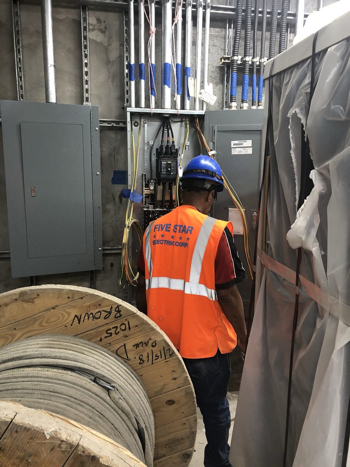
On site, those home runs become conductors pulled through conduit before the plaster goes on, terminated back at the panel as in the photograph below.
For students & site engineers: the point layout rarely shows the conductor count on each run (whether a leg carries 1, 2 or 3 wires plus earth). That is inferred from the switching logic and the circuit it belongs to, then conduited accordingly. Mounting heights are usually given as a note or a separate schedule, not dimensioned point-by-point — indicatively, switchboards at roughly 1200–1350 mm, general sockets at 300–450 mm, kitchen counter and AC points high — but always build to the project's stated heights, not these typical figures.
4. The single-line diagram (SLD) — the supply tree
If the point layout is the map of where, the single-line diagram is the story of how power gets there safely. It is drawn as a single line standing in for the whole multi-wire cable, branching downward from the supply to each circuit. It is a logic diagram, not a scaled plan, so do not measure anything on it.

Read it top to bottom:
1. Incoming supply & meter. Power arrives from the utility and passes through the energy meter (what you are billed on).
2. Main switch / isolator. A single switch (often a double-pole isolator or main MCB) that cuts all power to the house — the one you throw before any work.
3. RCCB (Residual Current Circuit Breaker). A life-safety device that watches for current leaking to earth — for instance through a person — and trips in milliseconds. It protects people from shock.
4. MCBs (Miniature Circuit Breakers). One per circuit. Each trips on overload or short circuit, protecting the wiring from overheating. They protect the cables.
5. Final circuits. The branches: lighting circuits, socket circuits, and dedicated circuits for heavy single loads like the AC, the geyser and the kitchen.
The crucial idea: RCCB protects you, MCBs protect the wires, and they work together. A common, sensible arrangement splits the house across more than one RCCB group so a single earth fault does not black out the whole home.
For students & site engineers: the SLD should show the incoming phase configuration (single-phase 230 V for most homes, three-phase 415 V for larger or higher-load houses), cable sizes per circuit, breaker ratings and breaking capacity, and the earthing arrangement. Earthing — the protective connection of metal parts to ground — is governed by IS 3043, while the wiring installation as a whole follows IS 732:2019. By IS 732 / IEC convention the earth conductor is green-yellow (commonly green in older practice), neutral is black, and phase is red or another live colour; confirm the colour code note on your set.
5. The distribution board (DB) and circuit numbering
The DB is the physical cabinet the SLD describes. Open its little door and you see a row of switches — that is your whole house, organised. The drawing that goes with it is the DB schedule, a table that names every circuit so anyone can find the right breaker in a hurry.

Before reading the schedule, it helps to know what the cabinet itself contains. Behind the door, left to right, sits the main isolator, then an RCCB, then the row of MCBs (one per circuit), all sharing a phase busbar above and an earth bar and neutral bar below.

A simplified schedule for a modest home might read like this (ratings and grouping are indicative — your design governs):
| Ckt | Feeds | MCB | Notes |
|---|---|---|---|
| C1 | Living & dining lights, fans | 6A | Lighting circuit |
| C2 | Bedroom lights & fans | 6A | Lighting circuit |
| C3 | General 6A sockets | 6A or 16A | Light-power points (breaker matched to cable size) |
| C4 | Kitchen 16A sockets | 16A or 20A | Dedicated |
| C5 | Geyser | 16A | Dedicated, wet area |
| C6 | AC | 16A or 20A | Dedicated |
| C7 | Spare | — | Keep one spare |
Two homeowner checks here. First, heavy appliances — geyser, AC, kitchen — should each sit on their own dedicated circuit, not share with the lights. Second, the schedule should be readable and, ideally, mirrored on a printed label inside the DB door so that years later anyone can switch off the right circuit without trial and error. A DB with no schedule, or unlabelled breakers, is a red flag.
For students & site engineers: good practice limits the number of points and the connected load on each final circuit (a lighting circuit is commonly capped at a modest number of points and a few hundred watts), keeps a spare way or two for future loads, and balances circuits across phases on a three-phase board. Diversity factor is applied when sizing the main and the service — the total of all circuits is never all on at once — but apply the values from IS 732 and the supply authority's norms, not a remembered rule of thumb.
6. Load — making sure the supply is big enough
Behind the whole drawing is one number the homeowner should ask about: the connected and the sanctioned load, in kilowatts (kW). Connected load is the sum of everything that could draw power; sanctioned load is what the utility has agreed to supply. The electrical design adds up your lights, fans, sockets and heavy appliances, applies a diversity factor (because not all run together), and arrives at the demand the house must be wired and metered for.
You do not need to do this maths, but you should confirm two things with your consultant: that the sanctioned load covers your real appliances (AC count, geyser, induction, EV charger if any), and that there is headroom for the future. Under-sanctioning shows up later as tripping breakers and a costly load-enhancement application. Over-provisioning the DB with a spare circuit or two now is cheap; adding one later is not.
For students & site engineers: present the load schedule alongside the SLD — point count and wattage per circuit, summed to connected load, then to maximum demand after diversity. This sizes the service cable, the main breaker and the metering, and is the basis of the load sanction submitted to the DISCOM. EV charging and rooftop solar are increasingly part of this estimate; flag spare capacity and a possible spare circuit for both. All load values must come from the actual appliance schedule, not generic per-point assumptions.
7. How to use this drawing
Read the legend first, then walk every room on the point layout as if you lived there — checking switches at doors, sockets where furniture and appliances land, and a 16A point for every heavy appliance. Then check the SLD and DB schedule: heavy loads on dedicated circuits, an RCCB for safety, a labelled board, and a spare way or two. Mark up anything missing in pencil and take it to your architect or electrical consultant before the conduiting starts — once the chasing and plaster are done, every change is a broken wall.
When you are ready to review the whole set together, use the Construction Drawing Review Checklist, and see how the electrical sheet must coordinate with the others in How All Construction Drawings Work Together — your AC points, for instance, must agree with the HVAC drawings, and your geyser and exhaust points with the plumbing drawings. If you have not yet appointed a consultant, find an architect; if you are still shaping the home itself, explore Studio Matrx DesignAI and our house plans.
Image credits
- Photograph (an electrician terminating branch-circuit wiring at an open electrical panel on site): MTA Capital Construction Mega Projects — CC BY 2.0, via Wikimedia Commons. Source: https://commons.wikimedia.org/wiki/File:Electricians_terminating_branch_circuit_wiring_in_a_power_substation_in_Queens._08-27-2019_(48647690926).jpg
References & Further Reading
Indian standards & manuals
- IS 732 : 2019 — Code of Practice for Electrical Wiring Installations (Fourth Revision), Bureau of Indian Standards. The governing standard for residential wiring design, erection and verification.
- IS 3043 — Code of Practice for Earthing.
- IS 2032 (series) — Graphical symbols for use in electrotechnology (the source of standardised electrical symbols).
- National Building Code of India (NBC) 2016, Part 8 — Building Services (electrical and allied installations), enforced through the State Electrical Inspectorates.
- IEC 60446 / IS conductor colour conventions for phase, neutral and protective earth.
Books / references
- B. L. Theraja & A. K. Theraja, A Textbook of Electrical Technology.
- V. K. Mehta & Rohit Mehta, Principles of Electrical Engineering and Electronics.
- Standard CPWD General Specifications for Electrical Works (Part I — Internal), Government of India.
Companion Studio Matrx guides
- Construction Drawings Masterclass — the pillar overview of the whole drawing set.
- Plumbing Drawings Explained and HVAC Drawings Explained — the other two MEP services.
- 50 Construction Drawing Symbols Every Homeowner Should Know — the visual glossary.
- How All Construction Drawings Work Together and the Construction Drawing Review Checklist.
Author's Note — I have stood in too many half-built rooms while a homeowner discovered, too late, that the only socket near the bed was on the wrong wall, or that the geyser and the lights tripped together because they shared a circuit. None of it was unavoidable. It was all there to be caught on a quiet evening with the drawing and a pencil. This guide is the evening I wish more people had spent. — Amogh N P
Disclaimer: This is an educational overview to help you read electrical drawings with more confidence. It is not a substitute for a licensed electrical consultant, a registered architect or a qualified MEP engineer. All ratings, heights, loads and circuit arrangements mentioned are indicative and typical only — act solely on the stamped, project-specific drawings prepared and certified for your home, and have all electrical work executed and tested by a licensed electrician in compliance with IS 732, IS 3043, NBC 2016 and your local supply authority's rules.
Export this guide
Related Guides — Deep-dive reading
Residential Electrical Systems: The Complete Guide for Indian Homes
How the electricity in an Indian home actually works — from the utility supply and meter through the distribution board, circuits, wiring, earthing and protection, to lighting, safety, energy efficiency, smart controls, solar and backup — written so a homeowner can understand, plan and judge it, and know exactly where a licensed electrician must take over.
Electrical & WiringBathroom Electrical Schedule (India): A Point-by-Point Wiring Table with Heights, Loads, Circuits & IP Zones
A working electrical points schedule an Indian architect, MEP consultant or site engineer hands to the electrician — every point with its height from FFL, load, circuit, IP zone and 30 mA RCD protection, so the bathroom is wired correctly, safely and to code.
BathroomsBathroom Planning for New Homes in India: Get It Right Before You Build
The bathroom decisions you cannot undo once the slab is cast — location and stacking, sunken vs non-sunken slabs, waterproofing, and the plumbing, electrical and ventilation you must coordinate with the civil work, stage by stage.
BathroomsRelated Tools — Try Free
Electrical Safety & Load Audit
Home electrical audit — 10 categories, 65+ checkpoints across earthing, RCCB, MCB, wiring, switchboards, appliance circuits, DG/inverter backup.
Safety AuditElectrical Load Calculator
Estimate a home's connected load and realistic maximum demand from its appliances, whether it needs single or three-phase supply, and a suggested main switch rating.
ElectricalApartment Furniture Size Chart
Standard furniture dimensions for Indian apartments — sofas, beds, tables, dining, storage.
Reference Chart