

50 Construction Drawing Symbols Every Homeowner Should Know
A visual glossary — the doors, windows, stairs, fixtures, electrical points, plumbing marks, section cuts and material hatches that turn a wall of lines into a readable house.
The first time you unfold a working drawing of your own house, it does not look like a house at all. It looks like a thicket of lines, arcs, dotted curves, little circles with letters in them, and patches that have been scribbled over with diagonal lines or dots. Somewhere in there is the bedroom you argued about for three weekends — but you cannot find it.
Here is the secret nobody tells the homeowner: a drawing is not a picture, it is a sentence. And like any sentence, it is made of words. Those arcs, circles, hatches and ticks are the vocabulary. Learn maybe fifty of them and the thicket resolves into a house you can walk through with your finger.
This guide is that vocabulary list — a visual glossary you can keep beside the drawing set and look up as you go.
A construction drawing symbol is a small, standardised mark that stands for a real building element — a door, a tap, a switch, or a material — so that a whole house can be described precisely on a flat sheet of paper.
This guide is for the homeowner who has been handed a set of drawings and wants to read them without an interpreter — and for the B.Arch or civil student and junior site engineer who wants the conventions pinned down precisely. It is a companion to the Construction Drawings Masterclass pillar. If you have not yet met the disciplines, read how architects read drawings differently than homeowners first; for the marks that appear specifically on services sheets, plumbing drawings explained and electrical drawings explained go deeper. Once you can read scale too — see understanding drawing scales — the lines start to mean dimensions.
A symbol is a promise: this little arc means a door, here, swinging this way — on every sheet, by everyone, the same.
One honest caveat before we start. There is no single all-India symbol law that every office obeys to the letter. IS 962 (the Indian Standard for architectural and building drawings practice) and the National Building Code (NBC 2016) set the conventions, and most are near-universal, but offices keep house styles. That is exactly why every good drawing set carries a LEGEND or KEY sheet near the front. The rule for a homeowner is simple: read this glossary to learn the grammar, then always cross-check against your set's own legend, because that legend is the final authority for your drawings.
1. How symbols are organised
Symbols arrive on your sheets sorted by discipline, the same way the drawing set itself is sorted. Architectural symbols live on the A-sheets, plumbing on the P-sheets, electrical on the E-sheets. Materials show up wherever something is cut through — mostly on sections and details. So this glossary follows the same four families:
| Family | Where you meet it | What it shows |
|---|---|---|
| Architectural | Floor plans, sections, elevations (A-sheets) | Doors, windows, stairs, levels, orientation, references |
| Plumbing & sanitary | Plumbing layouts (P-sheets) | Fixtures, traps, taps, supply & drainage marks |
| Electrical | Point layouts, single-line diagrams (E-sheets) | Switches, sockets, lights, fans, the distribution board |
| Materials (hatching) | Sections & details, anywhere a wall is cut | What a wall, slab or floor is made of |
For students & site engineers: two more distinctions matter. First, line type carries meaning before any symbol does — a solid line is something visible in the plane of the cut, a dashed/hidden line is something above or below it (a beam over, a chajja, a loft). Second, weight matters: the heavy, dark "poche" outline is the part actually sliced by the cutting plane; lighter lines are things seen beyond. Read the line before you read the symbol.
2. Architectural symbols
These are the marks on the A-sheets — the ones that draw the house itself: how you move through it, how light gets in, and how the sheets refer to one another. The plate below collects the dozen you will meet on almost every floor plan.

| Symbol | What it looks like | What it means in plain language |
|---|---|---|
| Single door | A short straight line (the open leaf) with a quarter-circle arc | A hinged door; the arc shows which way it swings and how much floor it sweeps |
| Double door | Two leaf lines with two arcs meeting in the middle | A pair of doors opening from the centre |
| Sliding door | Two parallel panels that overlap, no arc | A door that slides sideways instead of swinging — saves swing space |
| Window | A thin rectangle (two or three parallel lines) set into the wall | An opening for light/air; the lines suggest the glass and frame |
| Ventilator | A small window symbol placed high on the wall, often dashed | A high-level opening above door height, usually over a WC or kitchen |
| Staircase | Parallel lines (the treads) with an arrow marked UP or DN | Stairs; the arrow always points in the going-up direction from that floor |
| Break line (on stairs) | A diagonal or zig-zag line cutting across the flight | "The flight continues above the cut plane" — only the lower steps are shown |
| Ramp | A long sloped surface with a slope arrow and gradient note | A sloping path (1:12 typical for accessibility) instead of steps |
| Spot level / level mark | A small triangle or circle with a number like +0.600 | The reduced level (RL) — the exact height of that point above a datum |
| North point | An arrow, often in a circle, pointing to true/site north | Orientation; tells you which way the house faces (vital for Vaastu & sun) |
| Section cut line | A heavy line with arrowheads and a letter (A-A) at each end | "We slice the building here and look in the arrow's direction" — links to the section sheet |
| Grid bubble | A small circle with a letter (A, B, C) or number (1, 2, 3) | Names a structural gridline so a column or wall can be located precisely |
| Dimension line | A thin line with ticks/arrows at each end and a number above | The measured distance between two points, in millimetres unless noted |
Reading a door the way a professional does
A door symbol carries three pieces of information in one little arc: where the door is, which side the hinge is on, and which way it opens. That last one matters more than homeowners expect. A door that swings into a narrow passage, or into the path of another door, is a real-world collision drawn calmly in ink. When you scan a plan, trace each swing arc and ask: does anything stand where this arc sweeps?
Red flag: two door arcs that overlap, or a swing arc that crosses a fixed object like a WC or a wardrobe. The drawing is telling you the doors will clash — fix it on paper, not on site.
The single door on the legend plate is only the start. The same opening can be drawn six different ways, and the arc (or the absence of one) tells you which. The plate below lines up the door and window variants a homeowner most often confuses — a left-hand versus a right-hand single, a double or French pair, a bi-fold, a pocket slider that vanishes into the wall, and a sliding-folding run — and below them the window types in plan, where a casement shows its hinge side, a fixed window has no swing line at all, and a bay projects past the wall.

North point, levels and the reference marks
Three architectural symbols are not building elements at all — they are navigation aids, and homeowners skip them at their peril. The north point fixes orientation (and with it morning light and Vaastu). The spot-level mark gives you the exact height of a floor, a sill or a landing as a reduced level — a number measured up from a fixed site datum, so +0.600 means 600 mm above that zero. And the grid bubble and section-cut marker are the cross-references that let one sheet point to another: a section line on the plan tells you which section sheet to open, and the grid bubbles let the structural and services sheets all agree on where "gridline B" is.
In isolation each of these marks is simple; the skill is reading them together on a real fragment of plan. The worked example below shows a small two-room plan carrying all of them at once — grid bubbles numbered 1, 2, 3 across and lettered A, B down; a dimension string where two 3000 mm bays should add up to the 6000 mm overall figure below; a level mark in each room (the dining floor stepping down 150 mm from the living); and a section reference cutting through, labelled to send you to its sheet. Reading a sheet is exactly this: checking that the parts agree with the whole.

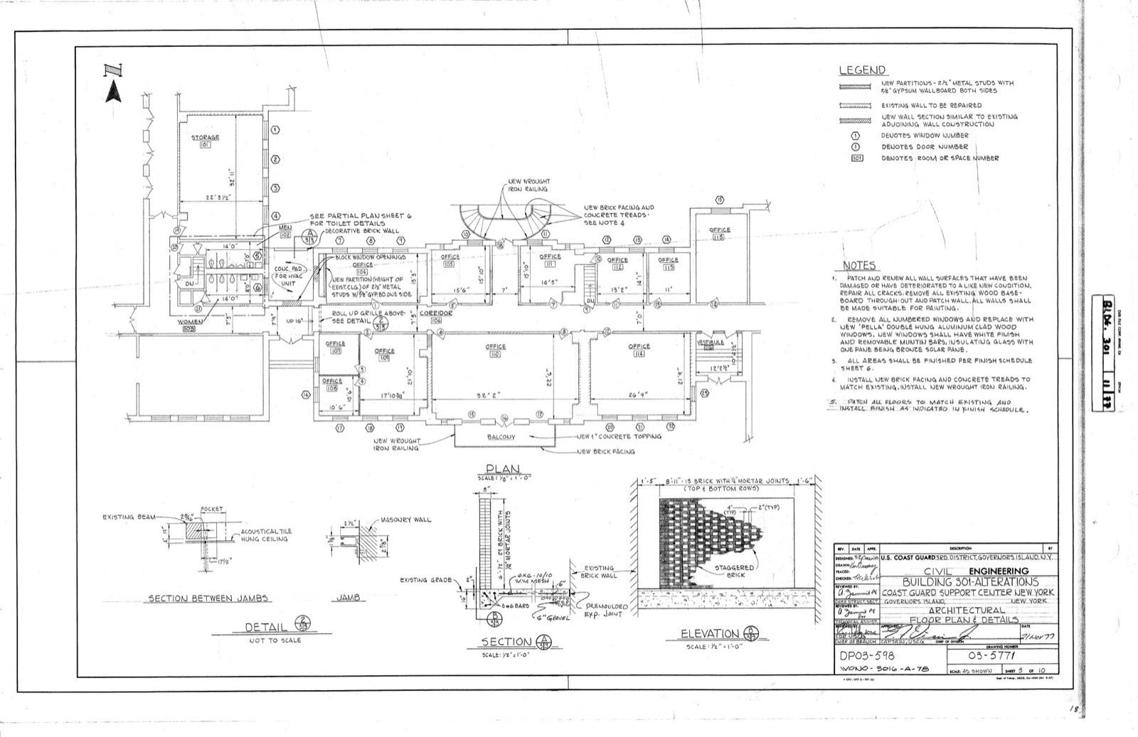
This is also what a real drawing sheet looks like once those marks are populated. The sheet below is an actual architectural floor-plan-and-details drawing: notice the boxed LEGEND at the top right that defines its own symbols (numbered markers for windows, doors and rooms, and the hatch for new partitions), the NOTES column, the dimension strings along the plan, the small section and detail drawings beneath, and the title block in the corner — the same grammar this guide describes, on a genuine production sheet.
3. Plumbing & sanitary symbols
Plumbing sheets carry two conversations at once: clean water arriving under pressure, and dirty water leaving by gravity. The fixtures and traps below are the nouns of that conversation. (For the line types and slopes that connect them, plumbing drawings explained goes further.)

| Symbol | What it looks like | What it means in plain language |
|---|---|---|
| WC (water closet) | An oval/rounded bowl in plan, with a rectangular cistern behind | The toilet; orientation shows which way it faces |
| Washbasin / wash hand basin | A rounded rectangle or half-oval against a wall | The bathroom basin |
| Sink | A rectangle with a bowl and a flat drainboard, in the kitchen | The kitchen sink |
| Shower | A square (the tray/area) with a small rose symbol in a corner | The shower position; often just a floor area with a trap |
| Bib tap / bib cock | A small circle with a short stem, on a wall line | A wall tap — the everyday tap you turn on |
| Floor trap (nahani trap) | A small square or circle with grating lines, set in the floor | A floor drain with a water seal that takes wash-down water and stops smells |
| Gully trap | A larger boxed trap, usually shown just outside the wall | Collects waste water from the bathroom before it joins the main drain; its water seal blocks odours and catches debris |
| Clean-out / inspection | A small capped circle on a drain line | An access point to rod/clear a blockage |
| Vent pipe | A pipe line marked V running upward, often dashed | Lets air into the drain so traps are not sucked dry |
| Rising main / supply | A solid line, sometimes labelled CW (cold) or HW (hot) | The pressurised water-supply pipe feeding the taps |
| Soil / waste pipe | A heavier line sloping to the stack, labelled S or W | Gravity drainage carrying waste away |
Why the trap symbols matter most
Of all the plumbing marks, the floor trap and gully trap are the two a homeowner should learn to spot, because they are the smell police of the house. Each holds a small plug of water — a "water seal" — that lets waste through but blocks sewer gas from coming back up. On the drawing they are small, easy to miss, and absolutely load-bearing for whether your bathroom smells fresh in three years. When you review a wet area, find every floor trap and ask: does the floor slope toward it?
For students & site engineers: Indian practice broadly follows IS 1742 (building drainage) and IS 2064 (selection, installation & maintenance of sanitary appliances), with NBC 2016 Part 9 (Plumbing Services) and the CPHEEO manual as the design references. Note that fixture symbols are conventionally drawn at the fixture's actual plan footprint and orientation, not as abstract icons — a WC symbol that faces the wrong way is a real instruction to the plumber, so orientation is information, not decoration.
Red flag: a WC or basin with no trap shown nearby, or wet areas on two floors that do not sit one above the other. Misaligned wet areas force long, shallow drain runs that block — the symbols are warning you before the tiles go down.
4. Electrical symbols
Electrical sheets map two things: every point (a place where power is used or controlled) and the circuits that feed them. The legend is the most important sheet to internalise, because almost everything on an electrical layout is a symbol. The right-hand half of the plate above collects the common ones; here they are spelled out.
| Symbol | What it looks like | What it means in plain language |
|---|---|---|
| One-way switch | A small dot/circle with a single short slash | An ordinary switch controlling a light or fan from one place |
| Two-way switch | A switch mark with a "2" or a paired slash | A switch that controls one light from two locations (top & bottom of stairs) |
| 6A socket | A socket symbol marked 6A (often a part-circle with lines) | A low-power point — phone chargers, lamps, TV |
| 16A socket | A socket symbol marked 16A | A high-power point — AC, geyser, fridge, microwave |
| Ceiling light point | A circle with a cross through it | A light fitting on the ceiling |
| Wall light point | A half-circle or circle against a wall | A light fixed to the wall |
| Fan point | A circle with small blades, or marked F | A ceiling-fan hook point |
| Exhaust fan | A circle with an arrow or marked EF, in WC/kitchen | A fan that pulls stale air out |
| TV / data / telephone point | A small box marked TV, TP or with a wedge | A media or communication outlet |
| Distribution board (DB) | A rectangle marked DB | The fuse/MCB box where all the circuits gather |
| Wiring run | A dotted or dashed curve linking a switch to its point | The cable route — which switch controls which light |
| Earthing | A symbol with stacked horizontal lines diminishing | The safety earth connection |
Reading the dotted curves
The faint dotted arcs that loop across an electrical plan are not decoration and not pipes — they are the wiring runs that tell you which switch operates which light or fan. Follow a curve from a switch and it lands on the points that switch controls. This is the single most useful skill on an electrical sheet: stand (in your imagination) at each door, find the switch, and trace its curves to confirm the right things turn on from the right place.
For students & site engineers: electrical installation practice in India follows IS 732 (code of practice for electrical wiring installations), with NBC 2016 Part 8 covering building services; the graphical symbols themselves derive from IS 2032 (graphical symbols used in electrotechnology, the Indian adoption of IEC 60617), though the sheet's own legend remains the authority. The point layout, the single-line diagram (SLD) and the DB schedule are three views of one system — the layout says where, the SLD says how it is fed and protected, and the schedule says which circuit number does what. A symbol on the layout should be traceable to a circuit on the schedule.
Red flag: a bedroom with the only switch behind where the door opens, a missing AC point on a wall that obviously needs one, or sockets shown without a rating. Catch these on the plan — moving a point after the conduits are cast in concrete is painful and ugly.
5. Material hatches (poche)
When a wall, slab or footing is sliced through in a section, the cut face is filled with a pattern — diagonal lines, dots, hatching, a solid tone. That pattern, called hatching or poche, tells you what the element is made of without a single word. Learn these nine and you can read what a wall is built from at a glance.

| Hatch pattern | What it looks like | What it means |
|---|---|---|
| Brick | Diagonal hatching, usually at 45 degrees | Brick masonry — a brick wall cut through |
| RCC (reinforced concrete) | A stipple of dots with small triangular aggregate marks | Reinforced cement concrete — columns, beams, slabs, footings |
| PCC (plain cement concrete) | A coarser, plainer dot pattern | Plain concrete — the lean levelling layer under footings & floors |
| Stone masonry | Irregular angular blocks fitted together | A stone wall — common in plinths and load-bearing rural construction |
| Earth / fill | Alternating short dashes and dots | Compacted soil or filling — below floors and around foundations |
| Plaster | A thin lined band on a wall face | The plaster finish coat over masonry |
| Timber / wood | Lines following the grain; rings for end-grain | Wood — doors, frames, joinery, sometimes roof members |
| Insulation | A soft zig-zag or cloud-like band | Thermal/acoustic insulation layer |
| Glass | A thin double line with a light tone | Glazing — windows, partitions, railings |
Why the difference between RCC and PCC matters to you
To a homeowner, "concrete is concrete." To your house, the difference between RCC and PCC is the difference between something that carries load and something that merely levels. RCC (the dotted-with-aggregate pattern) is the reinforced concrete of your columns, beams, slabs and footings — the bones. PCC (the plainer dot pattern) is the humble, unreinforced levelling layer poured first, under a footing or a floor, so the real work has a clean, flat base. When you read a foundation section, the thin PCC band at the bottom and the heavy RCC footing above it are two different materials doing two different jobs — and the hatching is what tells them apart.
For students & site engineers: IS 962 lays down the conventional hatching for materials in Indian practice, and offices broadly follow it, but — as with all symbols — the section's own legend governs. Note that hatching direction and density can also separate adjacent materials of the same family (two abutting walls hatched at opposing 45-degree angles, for instance), so read hatching not just for "what" but for "where one material ends and the next begins."
Red flag: a section where two different materials carry the same hatch, or a structural element shown with brick hatching where you expected RCC. Either the legend is wrong or the drawing is — and on a load path, that is worth a question to your engineer.
6. How to use this glossary
Do not try to memorise fifty symbols in one sitting. Keep this guide beside the drawings and look symbols up as you hit them, family by family. A practical order: start on the architectural plan and read doors, windows, stairs, levels and the north point; then open the plumbing sheet and find every fixture and trap; then the electrical sheet and trace the switch-to-light curves; and finally read the sections, where the hatches tell you what everything is built from.
Three habits will carry you the rest of the way. First, always check the symbol against your set's own legend sheet — it is the final word for your house. Second, read the line before the symbol — solid versus dashed, heavy versus light, tells you visible-versus-hidden and cut-versus-beyond. Third, treat orientation as information — a door swing, a WC facing, a slope arrow are instructions to the builder, not decoration.
When you are ready to put this to work, run your whole set against the construction drawing review checklist, and return to the Construction Drawings Masterclass to see how the sheets fit together. If you are still shaping the house itself, sketch and iterate plans with DesignAI, browse ready layouts in our house plans library, or find an architect to draw and stamp the real set.
Image credits
- Photograph (a real architectural floor-plan-and-details sheet with a legend, notes and title block): Department of Homeland Security. U.S. Coast Guard. 3/1/2003 — Public domain, via Wikimedia Commons. Source: https://commons.wikimedia.org/wiki/File:Building_301_Alterations_Architectural_Floor_Plan_and_Details,_November_21,_1977_-_DPLA_-_3d03961656892ed9c7cb1a9416b26304.tiff
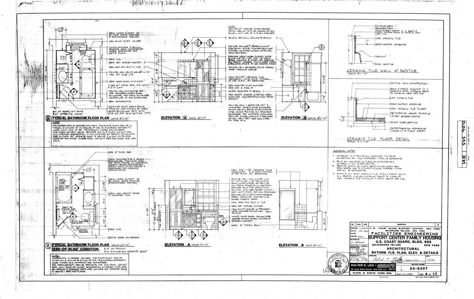
- Photograph (a real architectural bathroom drawing sheet with plan, elevations and tile details): Department of Homeland Security. U.S. Coast Guard. 3/1/2003 — Public domain, via Wikimedia Commons. Source: https://commons.wikimedia.org/wiki/File:Building_555_Architectural_Bathroom_Floor_Plan,_Elevation_and_Details,_March_1,_1989_-_DPLA_-_a703343359ce7c4488a83d8268c95cd1.tiff
References & Further Reading
Indian standards & manuals (verify each against the stamped issue used on your project)
- IS 962 — Code of practice for architectural and building drawings (conventions, symbols, hatching).
- National Building Code of India (NBC 2016) — general building practice; Part 8 covers Building Services (including electrical) and Part 9 covers Plumbing Services (water supply, drainage & sanitation).
- IS 1742 — Code of practice for building drainage; IS 2064 — selection and installation of sanitary appliances.
- CPHEEO Manual on Water Supply & Sanitation — reference for plumbing and drainage design.
- IS 732 — Code of practice for electrical wiring installations.
Books / references
- Francis D. K. Ching, Architectural Graphics — the standard primer on drawing conventions and symbols.
- Ernst Neufert, Architects' Data — fixture, fitting and dimension references.
- Bureau of Indian Standards (BIS) drawing-practice handbooks for material hatching and line conventions.
Companion Studio Matrx guides
- Construction Drawings Masterclass — the pillar overview of the whole set.
- How architects read drawings differently than homeowners
- Plumbing drawings explained · Electrical drawings explained
- Understanding drawing scales · Construction drawing review checklist
Author's Note — Amogh N P: I still remember the relief on a client's face the day a door symbol stopped being a squiggle and became, in her words, "the door I walk through to make tea." Symbols are not a wall built to keep you out of your own drawings; they are a shorthand built so that an architect, an engineer and a mason a hundred kilometres apart can all mean the exact same door. Learn a few, and the set quietly opens to you.
Disclaimer: This is an educational overview to help you read construction drawings; it is not a substitute for a licensed structural engineer, MEP consultant or registered architect. Symbol conventions vary between offices — your drawing set's own legend is the authority for your project. Act only on stamped, project-specific drawings; all conventions and any values mentioned here are indicative and must be confirmed against your issued drawings and the current Indian standards.
Export this guide
Related Guides — Deep-dive reading
Bathroom Plumbing Code India: NBC 2016 Part 9, UPC-I & the IS Standards That Govern Pipework
A professional reference to the codes and standards that govern bathroom plumbing in India — the National Building Code (NBC 2016) Part 9 on Plumbing Services, the Uniform Plumbing Code India (UPC-I), the CPHEEO Manual, and the IS standards for water supply, drainage, trap seals, pipe sizing, slopes and venting — with a caveat to always verify the current code and your local authority.
BathroomsBathroom Plumbing India: The Complete Guide to Water Supply, Drainage, Traps & Pipes
The whole plumbing picture for an Indian bathroom in one place — the two systems (cold and hot water supply, and waste/soil drainage with its vented SWV stack), traps and the floor trap, slopes and gradients, concealed vs exposed pipework, pipe materials (CPVC/UPVC/PEX/GI) and the overhead-tank pressure reality — with the coordination that must happen before any civil work starts.
BathroomsPlumbing Drawings Explained
Water in, waste out — how to read supply lines, drainage and vents, the symbols and line types, slopes and traps, shafts and the sunken-slab logic that keeps your bathroom dry.
Construction DrawingsRelated Tools — Try Free
Electrical Safety & Load Audit
Home electrical audit — 10 categories, 65+ checkpoints across earthing, RCCB, MCB, wiring, switchboards, appliance circuits, DG/inverter backup.
Safety AuditCross-Ventilation Analyzer
Estimate airflow and air changes per hour (ACH) from room size, window areas, layout, and local wind — with NBC 2016 Part 8 compliance check.
Ventilation CalculatorBathroom Drainage Pipe Calculator
Recommended drain and waste pipe sizes, slopes and stack size for a bathroom's fixtures — indicative IS 1172 / NBC plumbing practice.
Bathroom Calculator