

Plumbing Drawings Explained
Water in, waste out — how to read supply lines, drainage and vents, the symbols and line types, slopes and traps, shafts and the sunken-slab logic that keeps your bathroom dry.
Stand in a half-built bathroom before the tiles go on, and you will see the truth that the finished room hides: a tangle of pipes rising out of a sunken slab, some thin and shiny, some fat and grey, all heading in directions that seem to make no sense. The plumber knows where each one goes. You, holding the drawing, do not — yet. It looks like spaghetti.
It is not spaghetti. It is two completely separate stories told on one sheet. One story is about water arriving — clean, under pressure, ready to leap up to your shower the moment you open a tap. The other story is about water leaving — dirty, heavy, falling away by gravity, never to be seen again if everyone did their job. The plumbing drawing is simply these two stories drawn in two different line types over the same floor plan.
Once you can tell the in-story from the out-story, the spaghetti untangles, and you can check the single most expensive thing in your house to get wrong: whether the water that goes in will reliably come out.
A plumbing drawing is a floor-plan-based map of two systems — a pressurised water-supply network that pushes clean water up to your fixtures, and a gravity drainage network of soil, waste and vent pipes that lets dirty water fall away while keeping smells out.
This guide is for the homeowner who has been handed a plumbing sheet and wants to verify their bathrooms before the slab is cast, and for the B.Arch or civil student learning where these conventions come from. It sits inside our Construction Drawings Masterclass. Plumbing lives in a sunken slab, so read it alongside Roof & Floor Slab Drawings Explained; its symbols overlap with the symbols glossary; and when you are ready to sign off, use the review checklist.
Water finds its level and waste finds its slope. The drawing is just you making sure they find them on purpose.
1. Two systems, two line types
The first thing to do with any plumbing sheet is split it in two. Almost every confusion comes from reading a supply line as a drain, or the other way round.
Supply is the in-story. Clean water arrives from your overhead tank or the municipal main and travels through relatively small pipes — often 15 mm to 25 mm — under pressure. Because it is pressurised, supply can run uphill, sideways, anywhere; it does not care about gravity. On most Indian sheets supply pipes are 15 mm to 25 mm CPVC or GI, and the drawing distinguishes cold water from hot water (and sometimes a separate flushing/treated line) by different line types or labels like CW, HW and a rising main.
Drainage is the out-story. Used water and waste leave through much larger pipes — 75 mm, 110 mm, even 160 mm — and they run entirely by gravity. Every drainage pipe must fall continuously toward the stack. Drainage splits into soil (from WCs, carrying human waste), waste (from basins, sinks, showers — dirty but not soil), and vent (carrying air, not water, to protect the system).
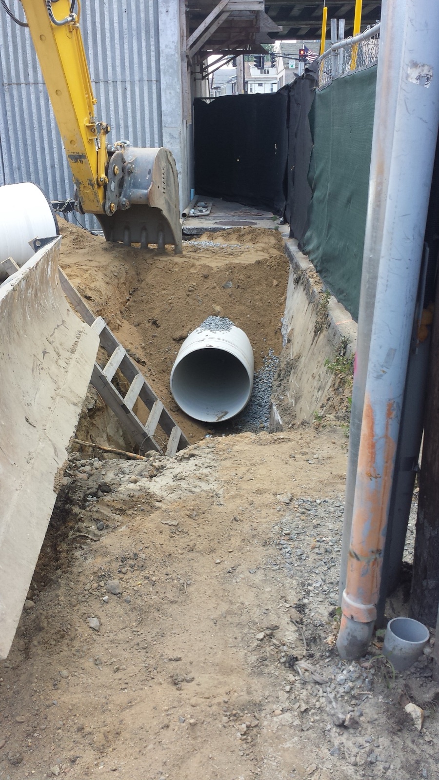
That heavy grey pipe is the physical reality behind the thick drainage line on your sheet: large bore, bedded on gravel, laid to a continuous fall toward a chamber. Supply pipes, by contrast, are the slim ones — which is exactly why the drawing gives the two systems different line types.

| Property | Supply (in) | Drainage (out) |
|---|---|---|
| What moves | Clean water | Waste & soil water, plus air in vents |
| Driving force | Pressure | Gravity (continuous fall) |
| Typical pipe size | 15–25 mm | 75–160 mm |
| Typical material | CPVC, GI, PEX | PVC, UPVC, CI (cast iron) |
| Can it run uphill | Yes | No, never |
| Drawn as | Thinner / dashed line type | Heavier / distinct line type |
All sizes here are indicative — your stamped drawing governs.
For students & site engineers: the discipline is governed by IS 1742, Code of Practice for Building Drainage, with sanitary-appliance selection and installation under IS 2064, and town-level sewerage by the CPHEEO Manual on Sewerage & Sewage Treatment. Supply-side design references the relevant water-supply codes and the National Building Code (NBC 2016) Part 9 (Plumbing Services).
2. Reading the symbols
A plumbing layout is built from a small alphabet of symbols. Learn the legend on your own sheet first — conventions vary between offices — but the common ones are remarkably consistent.

| Symbol on plan | Means | Notes |
|---|---|---|
| WC | Water closet (toilet) | Connects to the 110 mm soil pipe |
| WB / WHB | Washbasin / wash-hand basin | Waste line, with its own bottle trap |
| KS | Kitchen sink | Waste line, often via a separate gully |
| SH | Shower | Drains to a floor trap |
| FT | Floor trap (nahani trap) | Collects floor & shower water; water-sealed |
| GT | Gully trap | Outdoor trap collecting waste before the drain |
| CO | Clean-out / inspection eye | Access point to rod out a blockage |
| VP | Vent pipe terminal | Open to air, above roof |
| BT | Bib tap / bib cock | Wall tap for buckets, garden, washing machine |
The floor trap deserves a special note for Indian readers: the nahani trap in your bathroom floor is doing two jobs at once — it carries away shower and floor-washing water, and its water seal stops drain smells rising into the room.
3. Slope, traps and vents — the three things that make drainage work
This is the heart of the out-story, and the place where a beautiful-looking drawing can still be wrong.
Slope (fall)
A drain that is dead level does not drain — water sits, solids settle, the pipe chokes. Every horizontal drain is drawn with a continuous slope toward the stack, usually noted with a small slope arrow and a gradient like 1 in 60. Too flat and it blocks; too steep and the water races ahead leaving solids stranded, which also blocks. The sweet spot is self-cleaning velocity.
| Pipe | Typical fall (indicative) |
|---|---|
| 100–110 mm soil/waste branch | about 1 in 40 to 1 in 60 |
| Larger horizontal drains | gentler, around 1 in 80 to 1 in 110 |
These are indicative ranges aligned with IS 1742 practice; your drawing and consultant set the actual gradient.
Traps and the water seal
A trap is a U-bend that holds a plug of water — the water seal, typically around 50 mm deep. That little plug is the only thing standing between you and the smell of the sewer. Every fixture has a trap: the bottle trap under a basin, the P-trap behind a WC, the floor trap in the bathroom floor.

The geometry is simple but unforgiving: water collects in the bend, fills it to the crown weir, and anything more spills on to the drain — but that retained plug, the seal, stays put and blocks the gas behind it. Lose the plug to evaporation or siphonage and the barrier is gone.
Vents and anti-siphonage
Here is the subtle bit. When a slug of water rushes down the stack, it drags air with it and creates suction — and that suction can pull the water seal straight out of a nearby trap, leaving the path open for smells. The vent pipe is the fix: an open pipe to the atmosphere that lets air in to break the suction. This is anti-siphonage. On the drawing, vents are the pipes carrying no water that nonetheless run all the way up and out above the roof.

A trap without a vent is a smell waiting for the next flush.
For students & site engineers: this is exactly where the two-pipe versus one-pipe versus single-stack debate lives. A classic two-pipe system keeps soil and waste in separate stacks, each protected by its own vent — safest, most pipes. A one-pipe system combines soil and waste into a single stack but still gives every trap a dedicated anti-siphonage vent. A single-stack system goes further and drops the separate vent altogether, relying on a generously sized stack and self-venting geometry to protect the seals — fewest pipes, tightest rules. Indian residential practice commonly uses a single-stack or partially-ventilated single-stack arrangement; confirm which your sheet shows by counting the vertical pipes in the shaft.
4. The plumbing shaft and stacking wet areas
Now zoom out from one bathroom to the whole building section, and the single most important design idea appears: keep your wet areas stacked.
A plumbing shaft (duct) is a vertical chimney built into the plan purely to carry the stacks — soil, waste, vent and rising main — straight down through every floor. If every bathroom on every floor sits over the same shaft, the drains drop straight down: short, steep, reliable, easy to maintain.

When wet areas do not stack — the first-floor bathroom sits over the ground-floor living room — the drain has to crawl horizontally across the ceiling below to reach the shaft. Long horizontal runs mean shallow slope, slower flow, more joints, more chokes, and a false ceiling forever hiding a pipe that may one day leak over your sofa.
Engineers often summarise the whole shaft on a single schematic called a one-line riser (or stack) diagram. It is not to scale: every vertical line is one pipe and every fixture branch joins it, so you can check at a glance that each WC and basin drops into the right stack and that the vent runs all the way up and out.

Reading a riser diagram is a fast sanity check: count the vertical stacks, confirm there is a vent reaching daylight, and follow each fixture branch to the stack it joins. If a fixture seems to feed nothing, or a stack never reaches a chamber, that is a question for your consultant.
- Do: line up bathrooms, kitchens and utility areas floor-to-floor over a shaft.
- Do: keep the WC close to the soil stack so the soil run is short.
- Don't: float an upper-floor wet area over a dry room below.
- Red flag: a plumbing layout where the upstairs bathroom has no shaft beneath it on the floor below.
This is also why plumbing lives in a sunken slab: the bathroom floor slab is dropped (sunk) so the traps, branch drains and their slopes can all be buried within the depth, then filled and waterproofed, keeping the finished bathroom floor flush with the adjoining room. The sunken-slab logic is covered in Roof & Floor Slab Drawings Explained.
5. How a plumbing sheet talks to the other drawings
A plumbing drawing never works alone. The shaft it needs must be left as a cut-out in the slab drawing and clear of a beam or column; a drain that wants to drop through a beam is a clash that must be caught before casting. The way all these sheets coordinate on one grid is the subject of How All Construction Drawings Work Together.
| Check this on plumbing | Against this drawing |
|---|---|
| Shaft / pipe cut-outs exist | Slab layout |
| No drain drops through a beam | Beam layout |
| Sunken depth is enough for slope | Slab + section |
| WC under a soil stack, not a beam | Column & beam layout |
How to use this
Before your bathroom slab is cast, sit with the plumbing sheet and do three things. First, split it into the in-story (supply) and out-story (drainage) using the legend. Second, trace every drain from its fixture to the stack and confirm it slopes the whole way and passes a trap. Third, look at the building section and confirm your wet areas stack over a shaft.
If anything is unclear, that is a question for your plumbing consultant or architect, not a guess to make on site. Take it to the full Construction Drawings Masterclass, run the review checklist before sign-off, and if you are still assembling your team, find an architect or explore ready layouts in our house plans. You can also sketch your wet-area stack early with DesignAI.
Image credits
- Photograph (a PVC drainage pipe being installed in an excavated trench near a manhole): MassDOT — Public domain, via Wikimedia Commons. Source: https://commons.wikimedia.org/wiki/File:2014_07_22_Harvard_Street_Bridge_Drainage_-_PVC_Pipe_Installation_at_Manhole-1_(15034782225).jpg
References & Further Reading
Indian standards & manuals
- IS 1742: Code of Practice for Building Drainage — slopes, traps, vents, soil, waste & vent pipes.
- IS 2064: Selection, Installation & Maintenance of Sanitary Appliances — Code of Practice.
- CPHEEO Manual on Sewerage & Sewage Treatment (Ministry of Housing & Urban Affairs) — drainage gradients, self-cleaning velocity, minimum pipe sizes.
- National Building Code of India 2016 (NBC), Part 9 — Plumbing Services (water supply, drainage & sanitation).
Books / references
- Building Construction Illustrated, Francis D. K. Ching — services and section conventions.
- S. K. Hussain, Water Supply & Sanitary Engineering — Indian plumbing practice.
- G. S. Birdie & J. S. Birdie, Water Supply & Sanitary Engineering.
Companion Studio Matrx guides
- Construction Drawings Masterclass
- Roof & Floor Slab Drawings Explained
- Construction Drawing Symbols Every Homeowner Should Know
- Construction Drawing Review Checklist
Author's Note — Amogh N P: I have watched a family discover, two years after moving in, that a slow gurgle in the guest bathroom was an unvented trap losing its seal every time someone flushed upstairs. Nothing on the glossy finishes told them. The answer was on the plumbing sheet all along, in a vent line nobody had checked. I write these so that the next family checks.
Disclaimer: This is an educational overview to help you read plumbing drawings, not a substitute for a licensed plumbing or public-health engineer, MEP consultant or registered architect. All sizes, slopes, seal depths and pipe materials here are indicative and typical only — act only on your project's stamped, signed drawings and the advice of your consultants.
Export this guide
Related Guides — Deep-dive reading
Bathroom Plumbing India: The Complete Guide to Water Supply, Drainage, Traps & Pipes
The whole plumbing picture for an Indian bathroom in one place — the two systems (cold and hot water supply, and waste/soil drainage with its vented SWV stack), traps and the floor trap, slopes and gradients, concealed vs exposed pipework, pipe materials (CPVC/UPVC/PEX/GI) and the overhead-tank pressure reality — with the coordination that must happen before any civil work starts.
BathroomsBathroom Drainage India: Waste vs Soil Pipes, Slope, Sizes, Traps & Venting (2026)
How a bathroom's waste and soil pipes actually work — the difference between waste lines (basin, shower) and the soil line (WC), the fall you need, pipe sizes in mm, floor slope to the floor trap, how it all joins the stack, and how traps and venting stop blockages and smells.
BathroomsBathroom Plumbing Code India: NBC 2016 Part 9, UPC-I & the IS Standards That Govern Pipework
A professional reference to the codes and standards that govern bathroom plumbing in India — the National Building Code (NBC 2016) Part 9 on Plumbing Services, the Uniform Plumbing Code India (UPC-I), the CPHEEO Manual, and the IS standards for water supply, drainage, trap seals, pipe sizing, slopes and venting — with a caveat to always verify the current code and your local authority.
BathroomsRelated Tools — Try Free
Bathroom Drainage Pipe Calculator
Recommended drain and waste pipe sizes, slopes and stack size for a bathroom's fixtures — indicative IS 1172 / NBC plumbing practice.
Bathroom CalculatorPlumbing Pressure-Test & Leak Checklist
Pre-closure pressure and leak test — 9 categories, 60+ checkpoints across water supply, drainage, fixtures, waterproofing, hot water, tanks.
Pre-Closure TestFalse Ceiling Cost Estimator
Live ₹/sqft across 8 ceiling types — POP, gypsum, designer, metal, PVC, wooden — with cove and spot lighting for 20 Indian cities.
Cost Calculator