
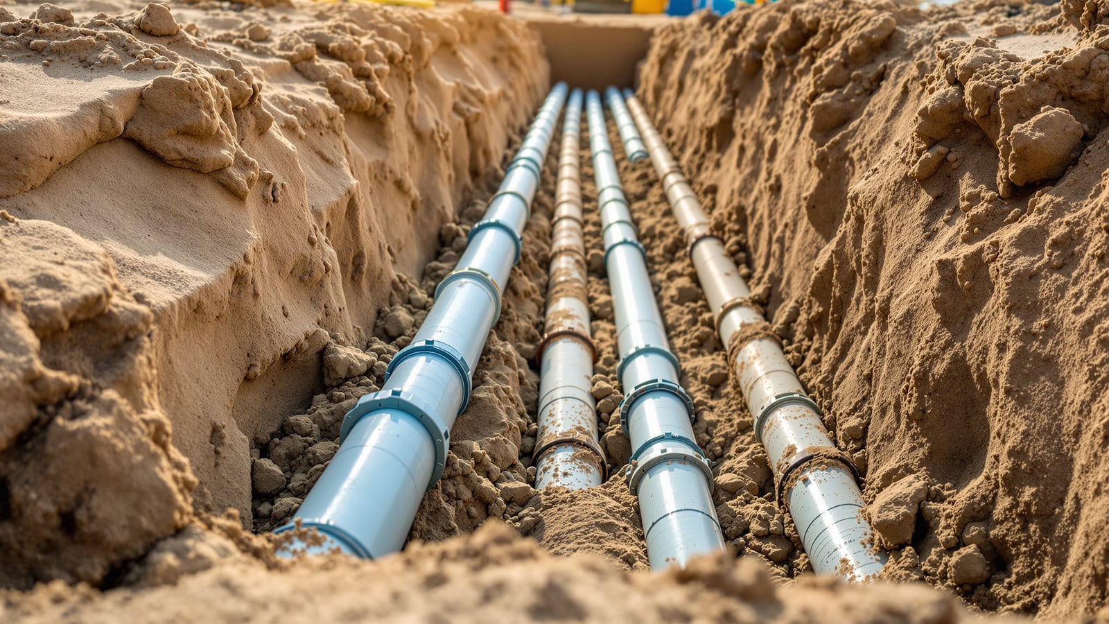
Underground Plumbing Installation in India: Trench, Bedding, Cover Depth and Backfill for Buried Water and Drainage Pipes
A site guide to laying water and drainage pipe below ground the right way — trench width and cover depth, the sand cushion and haunching that carry the load, warning tape, staged backfill and compaction, thrust blocks at bends, drainage gradient, and how to keep roots, settlement and point loads off the pipe.
Every buried pipe is a bet that you will never dig it up again. Get the trench, the bedding and the cover right and a water main or drain runs quietly for decades; get them wrong and the pipe cracks under a passing lorry, sags into a settled trench, or is punctured by a spade on the next job. This is a site guide to installing pipe below ground in India — the excavation, the support the pipe actually sits on, and the backfill that protects it.
This guide sits inside the Studio Matrx Plumbing Knowledge Hub. For the material landscape, start at the pillar plumbing pipes guide; the buried-main material of choice is covered in HDPE pipes; for how pipe is carried above ground instead, see pipe supports and hangers; and for the network these buried lines feed, see the forthcoming drainage systems guide.
A buried pipe does not float in the soil — it is a beam and a shell that carries earth load and traffic through the ground around it. Ninety per cent of good underground work is not the pipe. It is the bedding it lies on and the compacted fill you build up around its sides. Skimp on those and the best pipe in the world will fail.
When pipe goes underground — and which pipe
Pipe is buried for two jobs: pressurised water (municipal service line, borewell rising main, garden and irrigation supply, fire main) and gravity drainage (soil, waste and stormwater carried out to the sewer or a soak pit). The two are laid to different rules — pressure lines follow the ground and need thrust restraint at bends; drainage lines must fall at a steady gradient — but the trench, bedding and backfill discipline below is common to both.
Match the material to the duty and the depth:
- HDPE — the default for buried pressure water: coils in one jointless length, flexes with ground movement, immune to corrosion. See HDPE pipes.
- uPVC — rigid plastic for cold-water service and, in its ringtite/SWR grades, for buried drainage; cheap, light, corrosion-free. See uPVC pipes.
- Ductile iron (DI) — high-pressure trunk mains and heavy-cover crossings where a strong, restrained metal pipe is wanted. See ductile iron pipes.
- RCC / concrete — large-diameter gravity stormwater and sewer, and encasement duty. See concrete pipes.
Flexible pipe (HDPE, uPVC) leans on the compacted soil around it to hold its shape; rigid pipe (DI, RCC) carries load in its own wall. Both still need proper bedding.
The trench: width, depth and a safe cut
Set the trench width from the pipe, not from habit. Too narrow and you cannot compact fill down the sides; too wide and the earth load on the pipe rises. A workable rule is pipe outside diameter plus a working space each side.
| Nominal pipe dia | Practical trench width | Typical cover (garden / non-traffic) | Typical cover (under road / traffic) |
|---|---|---|---|
| Up to 90 mm | 300–450 mm | 600 mm | 900 mm |
| 110–160 mm | 450–600 mm | 750 mm | 900–1000 mm |
| 200–315 mm | 700–900 mm | 900 mm | 1000–1200 mm |
| 400 mm and above | OD + 300 mm each side | 1000 mm | 1200 mm and by design |
Cover is the depth of soil over the crown of the pipe, and it is what protects the pipe from surface load, from the frost-and-heat cycle, and from the casual spade. All figures above are indicative — confirm against the utility's standard and IS 12288 for the pipe you are laying.
Cut the trench with a flat, even bottom to the design invert. Remove stones, brick bats and old debris; never let the pipe rest on a rock or a lump of masonry, which becomes a point load that will crack it. In loose or deep ground, batter or shore the sides — a trench collapse is the single biggest safety risk on this work, and a person can be buried by a wall of soil in seconds.
Bedding and haunching: what the pipe actually sits on
The pipe must never sit on the raw trench bottom. It sits on a prepared cushion, and fill is worked in around its lower half so the load is carried evenly rather than on a line.
- Bedding (sand cushion): lay 100–150 mm of clean river sand or fine granular material on the trench floor and level it. This removes point loads and gives the pipe continuous support along its length.
- Bell holes: at each socket/coupling, scoop a small hollow in the bedding so the pipe barrel — not the joint — takes the bearing.
- Haunching: once the pipe is laid to line and level, work sand or fine fill down both sides into the haunch zone (from the bedding up to the pipe springline) and compact it by hand in layers. This is the step most often skipped, and it is the one that stops a flexible pipe deflecting and a rigid pipe rocking.
- Initial (side/top) fill: continue selected fill up to 300 mm over the crown, compacted in 150 mm layers, hand-tamped only — no mechanical rammer directly over the pipe yet.
Warning tape, backfill and compaction
Once the initial fill is over the crown, lay detectable warning/marker tape the full length of the run, 300 mm above the pipe — a coloured plastic tape (blue for water, others by service) that anyone opening the ground later meets long before a machine bucket reaches the pipe. For metal-detectable location, use tape with a metallised core or lay a tracer wire alongside plastic pipe.
Then complete the final backfill to grade:
- Backfill in layers of 150–300 mm, compacting each before the next. Uncompacted fill will settle, taking the road or paving above it down with it.
- Only use the mechanical rammer once there is at least 300 mm of compacted cover over the pipe — hitting a plastic pipe through thin fill will crack it.
- Under roads and paving, compact to a specified density and, where needed, cap with granular sub-base so the trench settles no more than the surrounding ground.
| Layer (from trench floor up) | Material | Compaction |
|---|---|---|
| Bedding, 100–150 mm | Clean sand / fine granular | Levelled, light hand tamp |
| Haunch (up to springline) | Sand / selected fine fill | Hand-tamped, both sides |
| Initial fill, to 300 mm over crown | Selected fill, no stones | Hand-tamped in 150 mm lifts |
| Warning tape | Detectable marker tape | Laid 300 mm above crown |
| Final backfill, to grade | Excavated / imported fill | Mechanical, 150–300 mm layers |
Protecting the pipe: roots, settlement and point loads
The threats to a buried pipe are slow and mechanical, not dramatic:
- Point loads — a rock under the pipe, a brick bat in the haunch, a joint bearing on hard ground. All of them concentrate load on a spot and crack the wall. The cure is clean bedding and bell holes.
- Settlement — poorly compacted backfill sinks, dragging a rigid pipe into a sag that pools drainage and shears joints. The cure is layered compaction.
- Roots — tree roots seek moisture and enter through drainage joints, then choke the line. Keep runs a sensible distance from large trees, use jointless HDPE or fully sealed joints near planting, and sleeve or reroute where you must pass close.
- Traffic and future digging — solved by adequate cover, warning tape, and concrete encasement or a sleeve where cover is shallow or a heavy crossing is unavoidable.
Thrust blocks and drainage gradient
Two details separate a professional job from an amateur one.
Thrust blocks — a pressurised pipe pushes outward at every bend, tee and dead end; the water tries to straighten the pipe and blow the fitting apart. Cast a concrete thrust block behind each bend and tee, bearing against undisturbed trench soil, sized to the pipe diameter, the operating pressure and the soil's bearing capacity. On flexible HDPE, fusion-welded and anchored joints or restrained fittings do the same job. Never rely on the backfill alone to hold a bend.
Drainage gradient — a gravity drain must fall at a steady, continuous slope: too flat and solids settle and block; too steep and water races ahead of the solids and leaves them behind. Lay to line and level with a laser or a boning rod, never by eye.
| Buried drain (nominal dia) | Minimum fall | Practical fall | Note |
|---|---|---|---|
| 100 mm soil / waste | 1 in 60 | 1 in 40 | Self-cleansing at design flow |
| 150 mm branch drain | 1 in 100 | 1 in 60 | Avoid over-steepening |
| 200–300 mm sewer | 1 in 150 | 1 in 100 | By flow calculation |
Testing and inspection before you backfill
Test before the trench is closed, never after:
- Pressure lines — hydrostatically pressure-test the laid pipe to the specified test pressure and hold it, watching for pressure drop, before final backfill. Charge slowly and bleed air first.
- Gravity drains — check line and level to the design invert, then run a water or air test on the section and confirm the flow at each manhole. Rod or CCTV the run for blockages and displaced joints.
- Concealed record — photograph the open trench with bedding, tape and cover visible, and mark the route on the as-built drawing so the next contractor can find the pipe.
Backfilling before testing is the classic false economy — a failed joint found after backfill costs many times what it costs to fix in the open trench.
Common mistakes on site
- Laying the pipe straight on the trench bottom with no sand bedding.
- Skipping the haunch, so fill bridges over the pipe and leaves voids at the sides.
- Backfilling in one dump and driving the rammer over thin cover — cracked pipe.
- No warning tape, so the line is invisible to the next excavation.
- No thrust block at a pressure bend — the fitting blows apart under test or in service.
- Drain laid by eye with a belly in the run — standing water and recurring blockages.
For the wider choice between running services buried versus in the wall, see the comparison of concealed and exposed plumbing; this guide covers only the buried case.
References
- National Building Code of India (NBC) 2016, Part 9 — Plumbing Services — water supply and drainage installation requirements.
- IS 12288 — Code of practice for use and laying of ductile iron pipes.
- IS 4984 — High density polyethylene pipes for potable water supplies (material and dimensions for buried water mains).
- IS 7634 — Code of practice for plastics pipe work for potable water supplies (selection, laying and jointing of PVC/plastics pipe).
- CPHEEO Manual on Water Supply and Treatment / Manual on Sewerage and Sewage Treatment, Ministry of Housing and Urban Affairs — trench, bedding, cover and gradient practice.
Trench widths, cover depths, layer thicknesses and gradients here are indicative for planning. Confirm every specific against the current IS code, the utility's standard drawing, the manufacturer's laying instructions and a licensed plumbing/water-supply engineer, and follow local trench-safety rules before excavating.
Export this guide
Related Guides — Deep-dive reading
Pipe Sizing for STPs: Velocity, Gravity vs Pumped Lines & Material Choice
How the pipework inside a sewage treatment plant is actually sized — the velocity limits that stop pipes silting up or scouring open, when to run gravity versus pumped lines, which materials survive sewage, and the design habits that keep an STP from choking on its own flow.
Sewage Treatment PlantsExternal Underground Drainage in India: Layout, Inspection Chambers, Gradients and the Connection to Sewer or STP
The buried gravity network that carries soil and waste from the building to the boundary — how it runs from the stack to the property line, where inspection chambers and manholes sit, the fall each pipe size needs, the materials and bedding that hold it, and how it hands over to a municipal sewer, a septic tank or an on-site treatment plant.
PlumbingPlumbing Pipes Guide: Every Material & How to Choose (India)
The section pillar for plumbing pipe materials in India — the full family of thermoplastics, metals, iron, concrete and clay, which pipe belongs on hot supply, cold supply, drainage, underground and sewer duty, a comparison-at-a-glance table, sizing basics, jointing methods, and a plain-language method for choosing.
PlumbingRelated Tools — Try Free
Garden Planning Toolkit
Get a tailored garden plan — planting layers, Indian species, features and a checklist — from your climate, space, sun and goals.
PlannerBathroom Drainage Pipe Calculator
Recommended drain and waste pipe sizes, slopes and stack size for a bathroom's fixtures — indicative IS 1172 / NBC plumbing practice.
Bathroom CalculatorBefore & After Studio
Generate AI before-and-after renders to preview how your redesign could look.
DesignAI