
Pipe Sizing for STPs: Velocity, Gravity vs Pumped Lines & Material Choice
How the pipework inside a sewage treatment plant is actually sized — the velocity limits that stop pipes silting up or scouring open, when to run gravity versus pumped lines, which materials survive sewage, and the design habits that keep an STP from choking on its own flow.
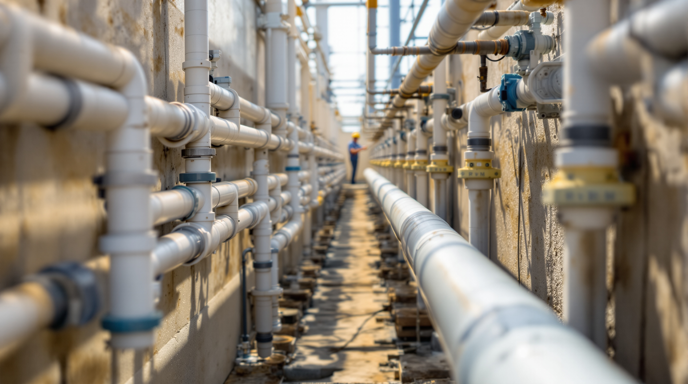
Pipework is the least glamorous part of a sewage treatment plant and the part most likely to fail in service. Blowers, membranes and dosing pumps get the attention on the tender drawing; the pipes get sized by rule of thumb, copied from the last job, or left to whoever routes the plant room. That is exactly why so many working STPs choke — a raw-sewage line that silts up every monsoon, a pumping main that hammers, a sludge pipe that blocks solid within a year.
Getting pipe sizing for STPs right is not complicated, but it is unforgiving. A pipe that is too small blocks and overflows; a pipe that is too large lets solids drop out and settle until it blocks anyway. The whole craft sits between those two failures, and it is governed almost entirely by one number: velocity.
Size an STP pipe for the velocity the flow will travel at, not just the flow it must carry. Sewage is water plus solids, and solids only stay in suspension inside a narrow band of speed. Miss that band and the pipe fails — too slow it silts, too fast it scours.
Why velocity, not just flow, sets the size
In a clean-water system you size a pipe to carry a design flow at an acceptable head loss and be done. Sewage is different because it carries grit, fibre, fats and biological solids that will settle out the moment the water slows down. So every sewage pipe has to be checked against two velocity limits, not one:
- Minimum self-cleansing velocity — the speed below which solids drop out and accumulate. For domestic sewage this is conventionally taken as around 0.6 m/s, ideally reached at least once a day at peak flow so the line scours itself clean.
- Maximum velocity — the speed above which the flow scours pipe walls, erodes fittings and, in pumped lines, drives up friction and energy cost. For most STP pipework this is held below about 2.5–3.0 m/s.
The design target is a pipe that runs somewhere in the 0.9–1.5 m/s band at its normal peak flow: comfortably self-cleansing, without punishing friction. Because the flow into an STP swings wildly between the 7 a.m. shower peak and 3 a.m. near-zero, the honest check is to size for the peak flow to guarantee self-cleansing, then confirm the pipe is not oversized at that peak.
Getting the design flow itself right comes first. The peak factor on average dry-weather flow is typically 2.5 to 3 for the small catchments an STP serves, and the whole calculation starts from the plant's rated capacity in KLD — the number the STP Capacity Calculator produces and the How to size an STP guide walks through.
Gravity lines versus pumped lines
STP pipework splits cleanly into two families, and they are sized on different principles.
Gravity lines carry flow downhill using the slope of the pipe alone — the incoming sewer to the plant, launder channels, overflows between tanks, and gravity returns. They run part-full (typically designed at half to three-quarter depth so air can move above the flow and carry off gases), and velocity is set by the slope you lay them at, not by a pump. Steeper slope, faster flow. The sizing job is to pick a diameter and a gradient together so the pipe is self-cleansing at peak yet not violently fast, and never surcharges.
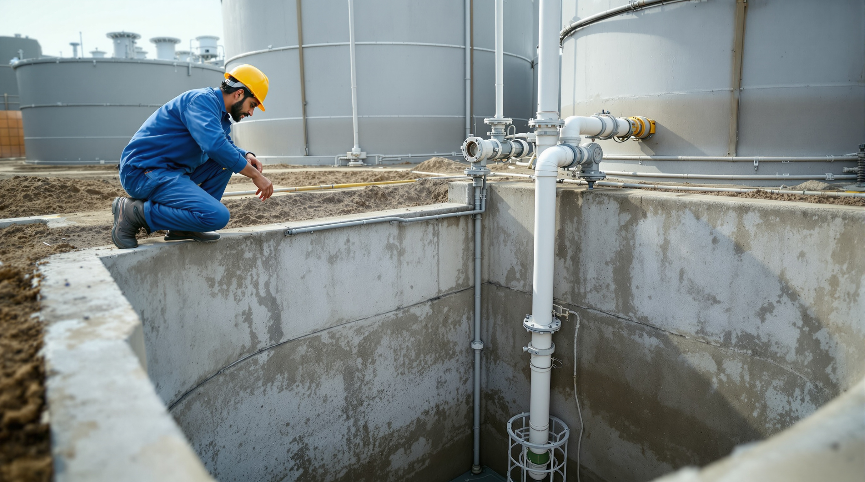
Pumped lines (rising / pressure mains) carry flow uphill or under pressure — the raw sewage lift from a below-grade sump, the filter-feed line, RAS/WAS sludge transfers, and the treated-water reuse main. These run full and velocity is set by the pump duty and pipe diameter. Here the trap is the opposite one: pick a diameter that gives a sensible velocity at the pump's design point, because an oversized rising main will let solids settle in the pipe every time the pump stops. The pump and pipe must be sized together — a topic the STP pumps and instrumentation guide covers in depth.
| Gravity line | Pumped (rising) main | |
|---|---|---|
| Flows because of | Slope of the pipe | Pump pressure |
| Pipe runs | Part-full (air above flow) | Full and pressurised |
| Velocity set by | Gradient you lay it at | Pump duty + diameter |
| Main sizing risk | Too flat → silts; too steep → scours | Oversized → solids settle when pump stops |
| Typical use | Inlet sewer, tank overflows, launders | Sump lift, sludge transfer, reuse main |
| Design levers | Diameter + slope together | Diameter matched to pump curve |
A well-planned plant uses gravity for as much of the internal journey as the levels allow and pumps only where it must lift — every pumped metre is energy you pay for forever, a theme the reducing STP electricity consumption guide returns to.
Material choice
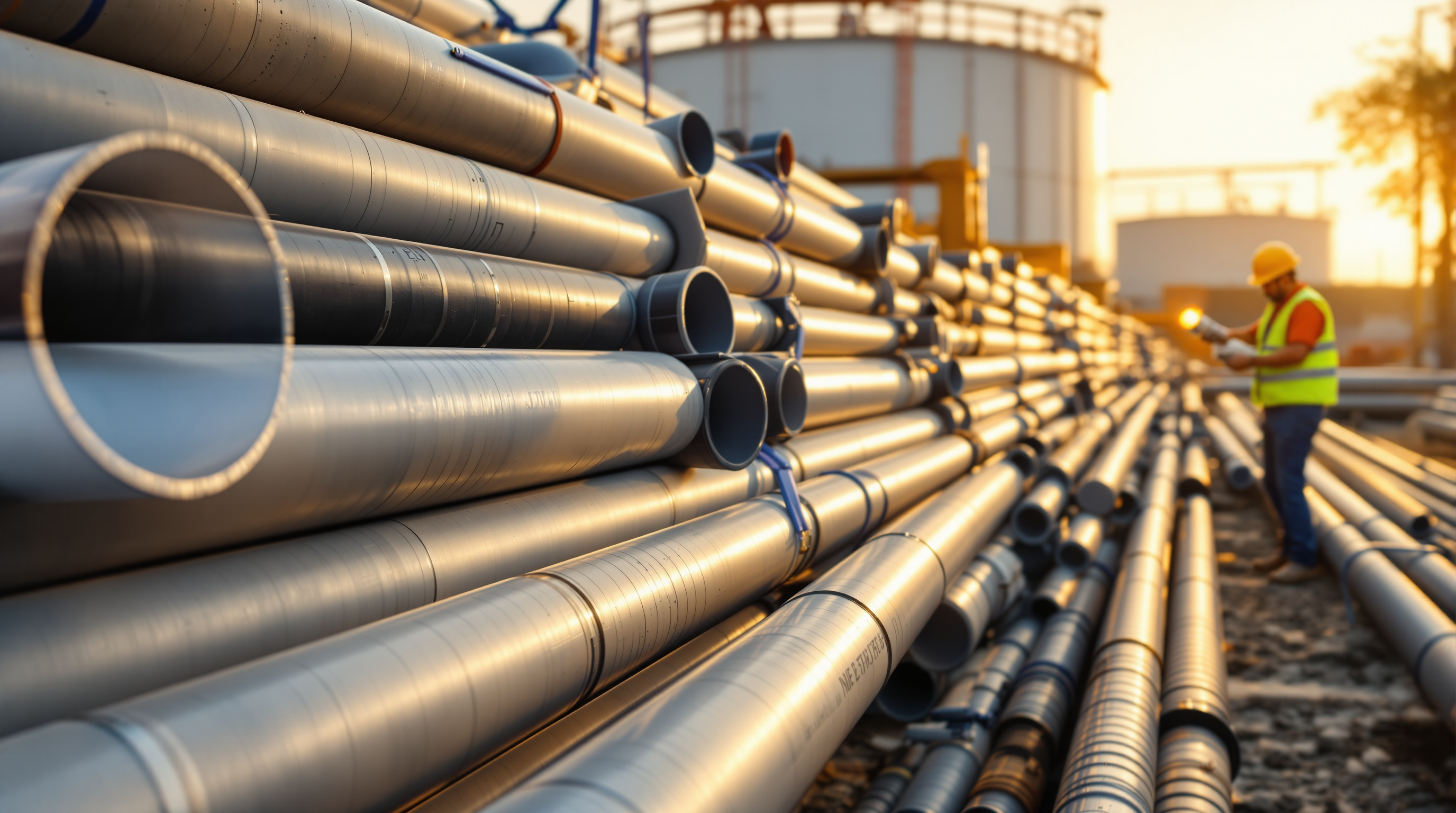
The pipe material has to survive sewage — which is mildly corrosive, sometimes septic and full of abrasive grit — and the H2S gas that collects in the air space above gravity flow and attacks the crown of the pipe. The practical menu for Indian STPs:
- UPVC — the workhorse for gravity drainage and low-pressure internal runs. Cheap, corrosion-proof, light, easy to solvent-weld. Not for high pressure or UV-exposed rooftop runs unless protected.
- HDPE — the default for pumped mains, buried lines and anything that must flex or take pressure. Butt-fused joints give a leak-free line, and it shrugs off H2S and grit. Slightly costlier but the safe choice for rising mains.
- CPVC / PPR — used where hot or chemically loaded flow occurs, and for some dosing lines.
- DI (ductile iron) / lined MS — reserved for large-diameter mains, high pressure, or exposed structural runs where mechanical strength matters. Must be lined internally; bare metal corrodes fast in sewage.
- Stainless steel — air and chemical dosing lines, and membrane-plant pipework where cleanliness and CIP chemicals demand it.
For chemical dosing and disinfection circuits, match the material to the chemical — the hypochlorite lines of a chlorination system are not the same duty as a raw-sewage pipe, and the UV disinfection guide chamber pipework has its own constraints.
The habits that prevent blockages
Sizing gets the diameters right; layout keeps them working. The recurring blockage-makers in real STPs are avoidable at the drawing stage:
- No pipe smaller than the solids it carries. Raw-sewage and sludge lines are conventionally kept at 100 mm minimum internal bore whatever the flow calc says — a smaller pipe blocks on a single rag.
- Sweep, don't elbow. Use long-radius bends and 45° junctions on sewage and sludge lines; sharp 90° elbows are where fat and fibre catch.
- Avoid dead legs and flat runs. Any pipe that holds stagnant sewage goes septic and silts. Give every line a fall, even a small one.
- Provide cleanouts and rodding access at every change of direction on gravity lines — you will need to clear them.
- Never oversize a sludge or rising main to "be safe." Thickened sludge at low velocity is the fastest-blocking pipe in the plant; keep it moving.
- Keep air-space ventilation on gravity lines so H2S does not concentrate and corrode the crown.
Sludge lines deserve special caution: RAS and WAS carry 0.8–2% solids that settle almost instantly, so they are sized for a firm self-cleansing velocity and run as short and straight as the layout allows — which is one more reason STP layout planning and pipe sizing are really the same exercise done together.
The bottom line
Pipe sizing for STPs comes down to a disciplined loop: take the peak design flow, pick a diameter (and, for gravity lines, a slope) that puts velocity inside the self-cleansing band without over-speeding, choose a material that survives sewage and H2S, and lay the run so solids never get a chance to settle. Do that and the pipework becomes the invisible, reliable part of the plant it should be. Skip it and every other rupee spent on the STP is at the mercy of a pipe that blocks.
From here, size the plant those pipes serve with the STP Capacity Calculator, and continue through the Sewage Treatment Plants guide library for the pumps, layout and process decisions that the pipework has to connect.
Export this guide
Related Guides — Deep-dive reading
STP Layout Planning: Arranging Tanks, Plant Room and Pipe Runs the Right Way
How to lay out an STP so sewage flows downhill by gravity, every tank can be reached for maintenance, and the plant can grow later — compared against real compact and linear arrangements used in Indian buildings.
Sewage Treatment PlantsSTP for High-Rise Buildings: Solving the Vertical Challenges
Why an STP in a tower is a different animal from one in a low-rise block — sharp peak flows, a basement site starved of air and light, treated water that has to be pumped forty floors up, and odour and fire clearances that decide whether the plant gets signed off at all.
Sewage Treatment PlantsThe Sewage Treatment Process Flow, Explained: Every Stage From Inlet to Reuse
Follow a drop of sewage through a typical STP — inlet, screening, aeration, clarifier, filtration, disinfection and reuse — as one connected flow, with a block diagram and a unit-by-unit table, in plain language.
Sewage Treatment PlantsRelated Tools — Try Free
Rainwater Tank Sizer
How big should your rainwater tank be? Computes annual harvest, recommended tank capacity in litres, water-bill savings, and payback — for 10 Indian cities.
RWH CalculatorApartment STP Planner
Plan an apartment complex sewage treatment plant from flats and occupancy — get population load, sewage flow, recommended STP capacity in KLD, treatment technology and approximate space.
PlannerSewage Generation Calculator
Estimate the daily sewage a building generates and its peak flow in KLD from occupancy, LPCD, sewage return factor and peak factor.
STP Calculator