
External Underground Drainage in India: Layout, Inspection Chambers, Gradients and the Connection to Sewer or STP
The buried gravity network that carries soil and waste from the building to the boundary — how it runs from the stack to the property line, where inspection chambers and manholes sit, the fall each pipe size needs, the materials and bedding that hold it, and how it hands over to a municipal sewer, a septic tank or an on-site treatment plant.
Everything that leaves a building through a soil or waste stack has to get to the boundary, and below ground it does so by gravity alone. The external underground drainage system is the buried network of pipes, chambers and channels that carries foul water and, on many sites, rainwater from the base of each stack out to the sewer, the septic tank or the treatment plant. It has no pumps in the ordinary case and no second chance: the fall is set once, the chambers are built once, and the whole thing then has to run silently for decades.
This guide sits inside the Studio Matrx Plumbing Knowledge Hub. It is the below-ground half of the pillar drainage systems guide; for the trench, bedding and backfill craft of laying the pipe, see underground plumbing installation. We cover the pipes and chambers that carry waste to the property line — the moment it is about treating that waste, follow the links to the treatment hub.
An external drain is not clever. It is a straight pipe, laid true to a fall, with a lid over every place it changes direction. Almost every blocked-drain callout traces back to breaking one of those three rules: a belly in the pipe, too little fall, or a bend with no chamber to rod from.
Where it starts and where it ends
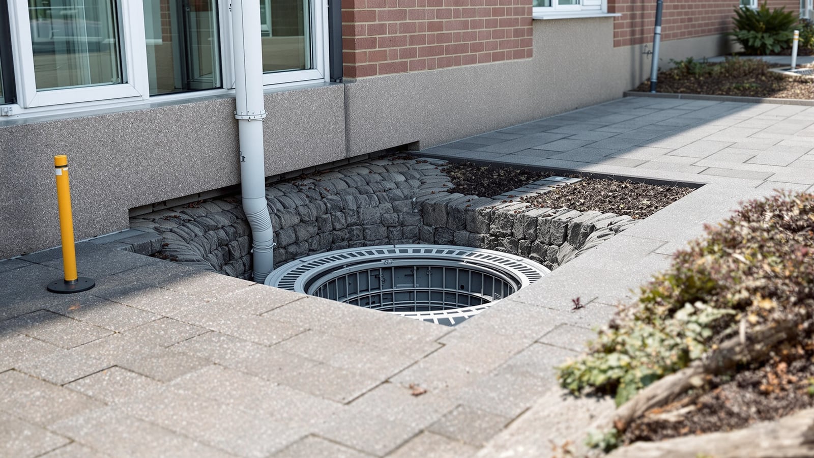
The system begins where the building stops. Each vertical soil or waste stack turns through a large-radius bend (a rest bend) at its foot and becomes a horizontal underground drain. Ground-floor gully traps — taking waste from kitchens, wash areas and floor drains — connect in through their own trapped gullies. Rainwater downpipes may join a combined drain or run to a separate storm line, depending on the local authority's rule.
From there the drain runs to the boundary, gathering branches, and terminates at the connection point: a public sewer, an on-site septic tank, or a packaged treatment plant. The golden run is as straight and as shallow as the fall allows, with every junction and change of direction made accessible.
- Stack to first chamber — a rest bend at the foot of each stack, then a short fall to the first inspection chamber. Never join a stack straight into a buried tee with no access.
- Branch drains — gully traps and secondary stacks feed in, ideally at a chamber or through a swept (obtuse-angle) junction facing the flow, never a square tee.
- The main run — the collector drain to the boundary, sized for the whole load, laid to a steady gradient.
- The connection — the last chamber before the boundary is the handover point to the sewer or treatment; see the connection section below.
Inspection chambers and manholes: the access rule
A buried drain is only as good as your ability to get into it when it blocks. That access is provided by inspection chambers (shallow, hand-depth, rodded from the surface) and manholes (deep enough to enter, with step irons). The governing principle, from NBC 2016 Part 9 and long practice, is that there must be a chamber at every point where you might need to rod, and no length of pipe that cannot be reached from one.
Put a chamber at:
- Every junction where a branch drain meets the main run.
- Every change of direction — bends carry the highest blockage risk, so each one gets access.
- Every change of gradient or pipe size.
- Regular intervals on straight runs, so a rod or a jetting hose can reach the whole length between two chambers.
- At the boundary, as the last accessible point before the drain leaves the property.
| Chamber / access type | Typical internal size | Depth to invert | Where it is used |
|---|---|---|---|
| Rodding eye | Pipe size + cap | At/near surface | End of a short branch, start of a run |
| Shallow inspection chamber | 450 × 450 to 600 × 600 mm | Up to about 900 mm | Junctions and bends near the surface |
| Deep inspection chamber | 600 × 600 to 900 × 600 mm | About 0.9–1.5 m | Deeper junctions, spacing on the run |
| Entry manhole | 900 × 800 mm and larger | Over about 1.5 m | Deep mains, the boundary connection |
Chamber spacing on straight runs is commonly held to around 30 m as a working maximum, closer on small-diameter drains where rods and jets have shorter reach — treat the figure as indicative and confirm against the local authority's drainage bye-laws. Inside each chamber the drain runs through a benched half-channel: the invert is a smooth open channel, and the sides are rendered up in cement mortar at a fall so any spill drains back into the channel rather than standing.
Gradient: the fall that makes it self-cleansing
A foul drain must run fast enough to carry solids but not so fast that the water outruns them and leaves them stranded. That balance is the self-cleansing velocity, and it is achieved by laying each pipe size to the right gradient. Smaller pipes need a steeper fall; larger pipes, carrying more flow, run clean at a gentler one.
| Nominal drain size | Typical foul gradient | Fall expressed as | Notes |
|---|---|---|---|
| 100–110 mm | 1:40 | 25 mm per metre | Branch and short main drains |
| 150–160 mm | 1:60 to 1:100 | 10–17 mm per metre | Main collector drains |
| 200–225 mm | 1:90 to 1:120 | 8–11 mm per metre | Larger foul / combined |
| 300 mm | 1:120 and flatter | By design | Site sewers, by calculation |
The classic rules of thumb — 1:40 for 100 mm and around 1:60 for 150 mm — are the ones to remember on site; the flatter figures for larger pipe apply only where the flow genuinely fills the pipe enough to stay self-cleansing. Two failures dominate real drains: too little fall, where solids settle and build a blockage, and a belly (a local sag where the pipe dips below grade), which does the same thing at a single low point. Both come down to laying discipline — a taut string line or laser to the design invert, and firm bedding so the pipe cannot settle. That craft is covered in underground plumbing installation.
Materials for the buried drain
The pipe below ground is chosen for strength under earth and traffic load, for a joint that stays watertight in the ground, and for a smooth bore. The material profiles already live in this hub — link them rather than re-specifying here.
- uPVC-SWR / ringtite drainage pipe — the default for house drainage in the 110 mm and 160 mm sizes: light, corrosion-free, quick to lay, jointed with rubber-ring sockets that tolerate movement. See uPVC pipes.
- RCC / concrete pipe — large-diameter site sewers, combined and stormwater mains, and encasement under heavy cover, where a strong rigid pipe carries the load in its own wall. See concrete pipes.
- Stoneware / vitrified clay — the traditional glazed, chemically inert foul drain, still specified where a rigid, abrasion- and effluent-resistant pipe is wanted. See clay pipes.
Flexible pipe (uPVC) leans on the compacted soil around it and needs a proper granular surround; rigid pipe (RCC, stoneware) still needs even bedding so it is not point-loaded. Whatever the material, the bedding and backfill rules are common.
Bedding, surround and cover
The pipe must never rest on the raw trench bottom or on a stone. It sits on a prepared granular bed — clean sand or fine gravel to a compacted layer under the barrel — with the same material worked in around the lower half (the haunch) and up over the crown before ordinary backfill goes on top. Under a road or driveway, or at shallow cover, the pipe may be given a concrete surround or bridged with a reinforced slab so traffic load bypasses it.
- Bed — around 100–150 mm of granular material, shaped so the barrel is continuously supported, with recesses cut for the sockets so the pipe bears on the barrel, not the joint.
- Surround — granular fill worked in and compacted around the sides and over the top; concrete surround where cover is shallow or load is heavy.
- Cover — depth of soil over the crown: commonly 600 mm in gardens and up to 900–1000 mm under traffic; indicative, confirm against the pipe standard and local rule.
- Marker — warning tape above the drain so the next spade knows it is there.
The full trench, bedding and backfill sequence is set out in underground plumbing installation.
The connection: sewer, septic tank or treatment plant
The last chamber on the property is where the private drain hands over. There are three destinations, and which one you have decides everything downstream — but not the drain itself, which is laid the same way to all three.
- Municipal sewer — the drain connects to the public sewer at a saddle or a junction the authority specifies, usually through a final boundary chamber (the intercepting or connection chamber). This is the simplest case: the drain carries foul water to the boundary and the utility takes it from there. For how a sewer connection compares with on-site treatment, see STP vs municipal sewer connection.
- Septic tank — where there is no sewer, the foul drain discharges to a septic tank, which settles solids and passes effluent to a soak pit or dispersal field. The drainage is your scope; the tank and its sizing are treatment, covered in the treatment hub.
- Sewage treatment plant (STP) — larger buildings and gated developments route the foul drain to an on-site packaged plant that treats the water for reuse. Again, the buried drain to the plant is your scope; the process inside it is not — see what is a sewage treatment plant.
Draw the line clearly. Everything up to and including the boundary chamber is drainage — pipe, fall, chambers, bedding. Everything past it, where the water is settled, aerated, filtered or reused, is treatment. Cross-link to the treatment hub the moment you cross that line, and do not try to do both jobs in one drain.
Access and maintenance over the life of the drain
A well-laid drain needs little, but it needs the little it needs. Keep every chamber cover findable and liftable — a chamber paved over or lost under a planter is a drain you cannot rod. Periodic rodding or jetting from the chambers clears grease and grit before it becomes a blockage; the benched channels let an operator see the flow. Root intrusion at old joints, a settled belly, and grease build-up on a flat gradient are the three long-term enemies, all found and fixed through the chambers built for that purpose.
- Record the drain layout — an as-built drainage plan showing chamber positions, inverts and directions of flow saves hours on the first blockage.
- Keep covers accessible and marked; never build over a chamber.
- Rod or jet from chamber to chamber, working with the fall.
- On a septic or STP connection, keep the boundary chamber clear so the interface can be inspected without entering the treatment unit.
For fixture-level detail on the drainage inside the bathroom that feeds these stacks, see the bathroom drainage pipe and floor-slope calculators in the Bathrooms hub; for the broader network logic, return to the pillar drainage systems guide.
References
- National Building Code of India (NBC) 2016, Part 9 — Plumbing Services (drainage, gradients and access for buildings).
- IS 1742 — Code of practice for building drainage.
- IS 4111 — Code of practice for ancillary structures in sewerage (manholes and chambers).
- IS 651 — Salt-glazed stoneware pipes and fittings.
- IS 458 — Precast concrete pipes.
- Confirm all gradients, chamber spacing and cover depths against the current codes and the local authority's drainage bye-laws before construction.
Export this guide
Related Guides — Deep-dive reading
Drainage Systems Guide for Indian Homes: DWV, Traps, Slopes & Stacks
The section pillar for household drainage — the two waste streams, gravity and gradients, traps and the water seal, the soil stack and branch layout, why venting matters, keeping foul and rain separate, and how it all connects to sewer, septic or an STP at the plot boundary.
PlumbingPlumbing Systems: The Ultimate Guide for Indian Homes & Buildings
The wide-angle pillar for the Studio Matrx Plumbing Knowledge Hub — what plumbing is, the two halves of every system (water supply and drainage/DWV), the whole-house water journey from source to fixture to drain, the main system types, and where conservation, building services and maintenance fit — with links down to every deeper guide.
PlumbingBathroom Plumbing India: The Complete Guide to Water Supply, Drainage, Traps & Pipes
The whole plumbing picture for an Indian bathroom in one place — the two systems (cold and hot water supply, and waste/soil drainage with its vented SWV stack), traps and the floor trap, slopes and gradients, concealed vs exposed pipework, pipe materials (CPVC/UPVC/PEX/GI) and the overhead-tank pressure reality — with the coordination that must happen before any civil work starts.
BathroomsRelated Tools — Try Free
Bathroom Drainage Pipe Calculator
Recommended drain and waste pipe sizes, slopes and stack size for a bathroom's fixtures — indicative IS 1172 / NBC plumbing practice.
Bathroom CalculatorRainwater Tank Sizer
How big should your rainwater tank be? Computes annual harvest, recommended tank capacity in litres, water-bill savings, and payback — for 10 Indian cities.
RWH CalculatorCross-Ventilation Analyzer
Estimate airflow and air changes per hour (ACH) from room size, window areas, layout, and local wind — with NBC 2016 Part 8 compliance check.
Ventilation Calculator