

Roof & Floor Slab Drawings Explained
The flat plane you live on and under — one-way and two-way slabs, slab thickness and level marks, openings and cut-outs, sunken slabs for bathrooms, and how to read a slab layout.
Stand in the middle of any room in your future house and look up. That ceiling — and the floor of the room above it — are the same thing: a flat plate of reinforced concrete, the slab. Now walk up to the terrace and stamp your foot. That is a slab too, except this one faces the sky and has to throw off the monsoon. The slab is the one element of your house you are always either standing on or standing under.
For something so ordinary, the drawing that controls it is quietly full of decisions. How thick is it? Which way does it bend under load? Where does the floor drop so a bathroom can hide its pipes? Where is the hole for the staircase? Each of these is a line or a note on the slab layout, and once you can read them, the sheet stops being a grid of rectangles and becomes a map of every surface you will live on.
A roof or floor slab drawing is the structural sheet that shows each horizontal concrete plate of your house — its panels, thickness, top levels, slopes, sunken portions and cut-outs — framed by the beams that carry it.
This guide is written first for the homeowner holding a slab sheet for the first time, and then, once each idea is in place, for the B.Arch or civil student and the junior site engineer who need the real depth behind it. It sits inside our Construction Drawings Masterclass pillar and follows naturally from Understanding Column Layout Drawings and Beam Layout Drawings Explained — because a slab is only ever as good as the beams and columns holding it up. When you have read it, run your sheet through the Construction Drawing Review Checklist.
The slab is the only part of the house you touch every single day — with your feet from above, and with your eyes from below. It deserves a careful read.
1. What a slab is, and why there is one drawing per floor
A slab is a flat, relatively thin plate of reinforced cement concrete (RCC — concrete with steel bars cast inside it) that spans between beams to make a floor or a roof. In a typical Indian framed house, the load path runs in a clear chain: the slab carries you and your furniture, the slab passes that load to the beams around it, the beams pass it to the columns, and the columns carry it down to the foundation.
Because every storey has its own arrangement of rooms, beams and wet areas, there is usually one slab layout drawing per floor level — a stilt or parking slab, a first-floor slab, a second-floor slab, and a separate terrace or roof slab on top. They look similar, but never assume they are identical. The roof slab in particular is its own creature: it has to drain water, take the sun, and often carry an overhead tank.
How to recognise the sheet
The slab layout is a plan view — a horizontal cut looking down — drawn on the same structural grid as your column and beam sheets, with the same lettered and numbered gridlines (A, B, C across; 1, 2, 3 down). On it you will see the beams as the boundaries of each panel, the panels themselves as plain rectangles, and a scatter of notes: a thickness, a level, an arrow, a shaded box. The rest of this guide is simply learning to read those four kinds of mark.
| Mark on the slab sheet | What it tells you |
|---|---|
| Panel outline (the beams around it) | One slab bay spanning between supports |
| Thickness note (e.g. 125 thk) | Overall depth of the concrete plate |
| Level note (e.g. +3.150 / TOS) | The top-of-slab level, height above datum |
| Slope arrow | The fall direction for draining rainwater |
| Shaded / hatched panel | A sunken slab (dropped for a wet area) |
| Dashed or cross-hatched void | A cut-out — a hole for stairs or a shaft |
A real sheet rarely shows a single panel — it shows a whole plate carved into many panels by the beam grid. Each panel gets its own mark (S1, S2, S3 …) and the gridlines running through it are the very same A–D / 1–3 lines you met on the column and beam sheets.

Read it this way: the solid squares are columns, the heavy double-lines between them are beams, and the rectangles those beams enclose are your slab panels. A square-ish panel like S2 is two-way; a long, narrow panel like S6 is one-way. The grid letters and numbers are your anchor — they must match across every structural sheet, which is the cross-check we return to at the end of this guide.
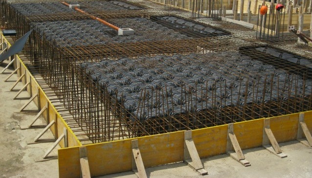
A drawing is one thing; the real plate is another. The photograph above is exactly what a slab layout becomes on site — edge formwork sets out the panel, a steel mesh fills it, and here rows of hollow void-formers lighten a ribbed slab before the concrete is poured over the lot.
For students & site engineers: slab design in India follows IS 456:2000 (plain and reinforced concrete). The slab layout you are reading is the structural general-arrangement drawing; the steel inside each panel is detailed separately on the reinforcement sheet, which we unpack in Reinforcement Drawings Simplified. Keep the two open side by side — the layout fixes geometry, the detail fixes steel.
2. One-way and two-way slabs: which way does it bend?
Here is the single most important idea on the sheet, and it is genuinely simple once you picture it. A slab supported on beams bends under load like a sheet of paper resting on a frame. The question is: does it sag mainly in one direction, or in both?

If a panel is long and narrow — clearly more than twice as long in one direction as the other — the load takes the short cut to the two nearer beams, and the slab effectively bends in one direction only. That is a one-way slab. If a panel is closer to square, the load shares itself across all four edges and the slab bends both ways. That is a two-way slab.
The 2:1 rule
The dividing line professionals use is a ratio. Take the longer span and divide it by the shorter span:
- If longer-span divided by shorter-span is greater than 2, it behaves as a one-way slab (spans the short way only).
- If that ratio is 2 or less, and the panel is supported on all four edges, it is a two-way slab (spans both ways).
This is not a cosmetic label. It decides which direction the main steel runs, how thick the slab needs to be, and how the panel is detailed. A 3 m x 7 m corridor slab is one-way; a 4 m x 5 m bedroom slab is two-way. Square-ish rooms are more efficient because both directions help carry the load.
For students & site engineers: the ratio rule comes from the relative stiffness of the two spans — at the point where the two directions cross, they must deflect by the same amount, and since a strip's deflection grows with the fourth power of its span, the load shares out roughly in inverse proportion to the fourth power of the span. So once the long span is more than twice the short, its share collapses to a few percent and one-way behaviour is assumed. One-way slabs are detailed with main bars along the short span and nominal distribution steel across; two-way slabs (IS 456 has coefficient methods in Annex D) carry main steel both ways and need corner reinforcement where corners are held down against lifting. Treat all of this as the convention behind the layout — the actual bar layout is on the stamped reinforcement sheet, never scaled off the slab plan.
Picturing where that steel physically sits makes the whole idea concrete. The slab sags in the middle and lifts (hogs) over its supports, so the bars track the tension: main bars near the bottom face across the midspan, and a second set of bars near the top face over each beam.

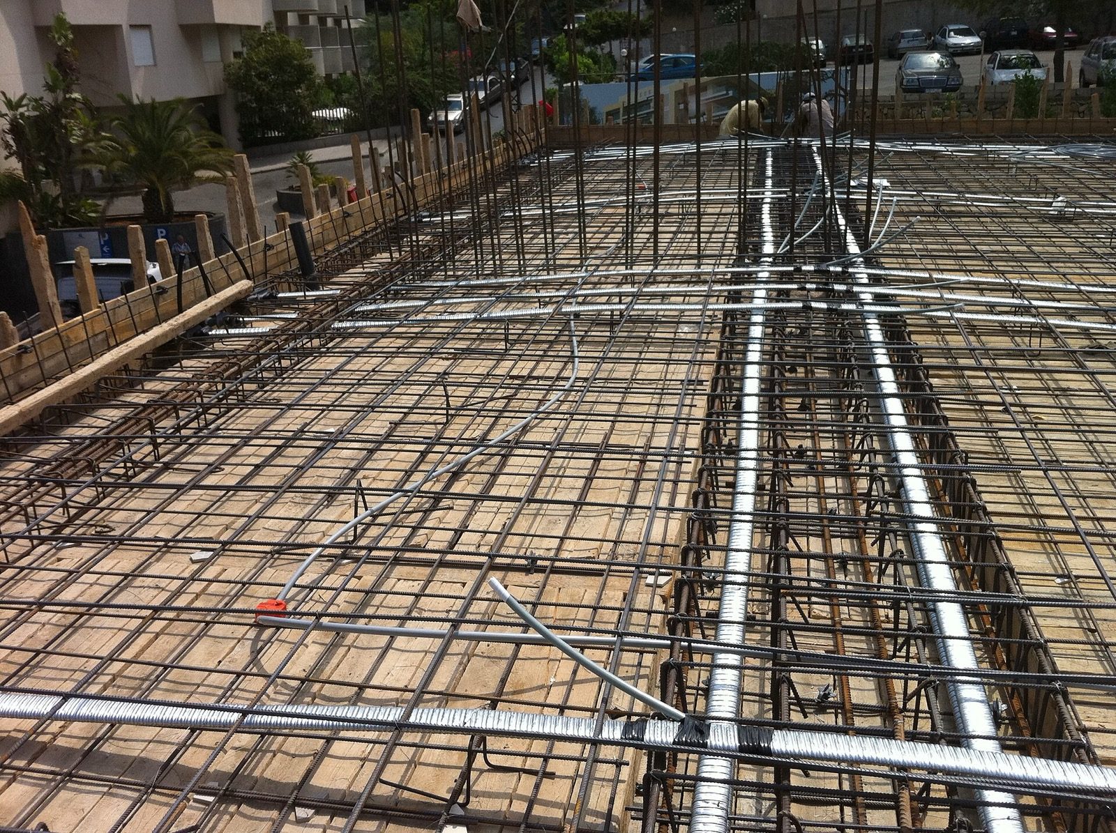
What the section above draws as a few lines is, on a real floor, the dense steel grid in this photograph — bars tied both ways across the formwork, with heavier beam cages threading through where the panel edges will be. The slab plan fixes where this all sits; the reinforcement sheet fixes the bars themselves.
This is exactly the steel that the reinforcement sheet schedules in full — we walk through bar marks, spacing and cover in Reinforcement Drawings Simplified. On the slab layout itself you usually see only the panel and its notes; the bars live on the detail.
3. Reading the notes: thickness, levels, slope and cut-outs
With the panels classified, the rest of the slab sheet is a set of written call-outs sitting on or beside each panel. This is where a homeowner can do a genuinely useful read.

Thickness
A note like "125 thk" or "150 THK" is the overall depth of the slab in millimetres. For ordinary residential rooms in India the slab is commonly 125 mm or 150 mm thick — these are indicative ranges only; your engineer sets the real figure from the span and loads. As a rough sanity check, the larger the room a panel spans, the thicker it tends to be. Roof slabs are often a touch thicker than floor slabs to carry water-proofing, screed and the occasional tank.
The governing logic, for the curious, is the span-to-depth ratio in IS 456: a simply supported slab is kept around span-over-20, a continuous slab around span-over-26, modified for the steel provided. A 4 m room landing near 150 mm overall is exactly what you will see in 99 per cent of Indian apartment drawings. Again — indicative; act on the stamped value.
Levels
A level note such as "+3.150 (TOS)" gives the top-of-slab level — its height above the project datum (usually ground or plinth level taken as 0.000). TOS means top of slab; FFL, which you will also meet, means finished floor level, i.e. after tiles and screed sit on top. The gap between TOS and FFL is the floor-finish thickness. Levels matter most where one slab steps down from another — a balcony, a toilet, a terrace.
Slope and rainwater outlets
On a roof or terrace slab, and on open balconies, you will find a small arrow with a note like "slope 1 in 100 to RWO". RWO is the rainwater outlet — the drain hole. The slope is the deliberate fall built into the surface so water runs to the outlet instead of ponding. A fall of roughly 1 in 100 to 1 in 80 (about 10–12 mm per metre) is typical Indian practice for terraces; the arrow always points downhill, toward the outlet. Standing water is the enemy of a flat roof, so trace every arrow and make sure each one ends at an outlet, never at a parapet corner with nowhere to go.
Red flag: a terrace slab with no slope arrows, or arrows that point toward a wall instead of a drain. Ponding water finds every crack — make your engineer show the falls.
Cut-outs
A cut-out (also called an opening or void) is a deliberate hole left in the slab, drawn as a dashed or cross-hatched outline with a note. The big ones are for the staircase (so people can pass between floors) and for vertical shafts that carry plumbing pipes, electrical risers or ducts up the building. A homeowner's check: every staircase needs a matching cut-out in the slab above it, and every stacked bathroom should sit near a plumbing shaft cut-out. We cover why those wet areas must line up in Plumbing Drawings Explained.
| Call-out on the sheet | Reads as | Homeowner check |
|---|---|---|
| 125 thk | 125 mm overall slab depth | Bigger rooms, thicker slab — sanity only |
| +3.150 TOS | Top of slab at 3.150 m above datum | Steps and drops between rooms make sense |
| Slope 1 in 100 to RWO | Fall to rainwater outlet | Every roof arrow ends at a drain |
| Dashed void + note | Cut-out for stair / shaft | Stair and stacked toilets have their holes |
4. Sunken slabs: how a bathroom hides its pipes
Walk into a well-built bathroom and the floor sits flush with the bedroom outside, yet somehow all the drain pipes, the trap below the WC and the floor drain have vanished. They are hidden in a sunken slab.

A sunken slab is a portion of the floor cast lower than the surrounding slab — typically dropped by about 200 to 300 mm (indicative) — so the bathroom's pipework can run within that recess instead of dangling below the ceiling of the room downstairs. On the slab plan it is shown as a shaded or hatched panel with a note like "SUNK 300" giving the drop.
The build-up inside the sunk, from bottom to top, is a careful sandwich: the dropped RCC slab itself, a waterproofing treatment, the buried plumbing, a lightweight fill (broken bricks, AAC offcuts or a light cinder/cement fill) to bring the level back up, a second waterproofing layer, and finally the floor screed and tiles. The whole point of the dimensioning is that the finished floor of the bathroom lands flush with — or a few millimetres below — the adjoining room, so there is no awkward step and no water escaping outward.
For students & site engineers: the sunken portion is where water-tightness is won or lost. The dropped slab and its joints are usually cast with an integral waterproofing admixture for dense, watertight concrete, and the watertightness logic follows IS 3370 (concrete structures for liquid retention) for the ponding/leak test — commonly a seven-day ponding check before fill. Note that the fill adds dead load, so the sunk panel is designed for that extra weight. The cleanest detail keeps the sunk depth just enough for the drainage fall under the WC trap; over-deep sunks waste fill and load.
Red flag: a bathroom with no sunken panel shown on the slab plan and no clear note about how its plumbing is concealed. Surface-routed or ceiling-hung bathroom drains in the room below are a recipe for leaks and ugly boxing-in.
5. How the slab sheet talks to the beam and column sheets
A slab never stands alone. Its panel boundaries ARE the beams from the beam-layout sheet, and those beams land on the columns from the column-layout sheet. Read the three together and the structure makes sense as one frame.
Three quick cross-checks a homeowner can do without any engineering training:
- Every panel is closed by beams. A slab panel needs support on its edges. If a panel edge has no beam (or wall) under it, ask why.
- The grid matches. The gridlines, dimensions and column positions on the slab sheet must be identical to those on the column and beam sheets. Mismatched grids between sheets is a coordination error — exactly the kind of thing we hunt for in How All Construction Drawings Work Together.
- Levels are consistent. The TOS on the slab sheet should agree with the beam tops and the floor levels written on the architectural sections.
This is also where a small change becomes expensive. Move a bathroom, and you move its sunken panel, its shaft cut-out and possibly a beam — across three drawings at once. That ripple is why slab decisions are best frozen early, alongside the column and beam layouts, before a single bag of cement is opened.
How to use this
Read your slab sheets in this order: identify the floor (which level is this?), classify the big panels as one-way or two-way by eye, then walk the notes — thickness, levels, slopes on the roof, sunken panels at every wet area, and cut-outs at the stair and shafts. Cross-check the grid and levels against your beam and column sheets. Anything that does not add up is a question for your engineer, not a guess for the site.
From here, go back up to the Construction Drawings Masterclass pillar to see where slabs sit in the full set, then carry your whole drawing set through the Construction Drawing Review Checklist before any pour. If you are still shaping the home itself — rooms, spans and where the wet areas land — explore ready, structurally sane layouts in our house plans library, try an idea in DesignAI, or find an architect to stamp the real thing.
Image credits
- Photograph (suspended ribbed-slab formwork with steel mesh and void-formers before concreting): Daniele Bartolini — CC BY-SA 3.0, via Wikimedia Commons. Source: https://commons.wikimedia.org/wiki/File:Cassero_per_vespaio_aerato_con_chiusure.jpg
- Photograph (dense slab reinforcement mesh tied over formwork before the pour): Elie Malti — CC BY-SA 4.0, via Wikimedia Commons. Source: https://commons.wikimedia.org/wiki/File:Bonded_post-tension.JPG
References & Further Reading
Indian standards & manuals
- IS 456:2000 — Plain and Reinforced Concrete, Code of Practice (slab classification, span-to-depth ratios, two-way slab design coefficients).
- IS 3370 (Parts 1–4) — Concrete Structures for the Storage of Liquids / water-tightness practice (relevant to sunken-slab waterproofing and ponding tests).
- IS 875 (Part 2) — Design loads (imposed/live loads) for buildings, which set what a slab must carry.
- IS 962 — Code of practice for architectural and building drawings (drawing conventions).
- National Building Code of India (NBC) 2016 — general building and drainage provisions.
Books / references
- Pillai & Menon, Reinforced Concrete Design (Tata McGraw-Hill) — slab behaviour and detailing.
- B. C. Punmia, Reinforced Concrete Structures — worked one-way and two-way slab examples.
- N. Krishna Raju, Reinforced Concrete Design — Indian-code-based slab design.
Companion Studio Matrx guides
- Construction Drawings Masterclass — the pillar overview.
- Understanding Column Layout Drawings and Beam Layout Drawings Explained — what holds the slab up.
- Reinforcement Drawings Simplified — the steel inside the slab.
- Plumbing Drawings Explained — why wet areas stack over sunken panels.
- How All Construction Drawings Work Together and the Construction Drawing Review Checklist.
Author's Note — Amogh N P. I still remember the first slab sheet I was handed as a student: a page of empty rectangles that I was sure meant nothing. The day someone showed me that a long-narrow box bends one way and a square box bends both ways, the whole sheet lit up — I could suddenly see the floors doing their quiet work. I hope this gives you that same small click, standing in your own future rooms, looking up.
Disclaimer. This is an educational overview to help you read slab drawings; it is not a substitute for a licensed structural engineer, MEP consultant or registered architect. All thicknesses, levels, slopes, sunk depths and ratios here are indicative and typical — never design values. Build and pour only from stamped, project-specific drawings prepared and signed for your site.
Export this guide
Related Guides — Deep-dive reading
Beam Layout Drawings Explained
How the beams that carry your slabs are drawn — beam marks, sizes, the difference between a beam you can see and one hidden in the slab, and why beams must land on columns.
Construction DrawingsBathroom Planning for New Homes in India: Get It Right Before You Build
The bathroom decisions you cannot undo once the slab is cast — location and stacking, sunken vs non-sunken slabs, waterproofing, and the plumbing, electrical and ventilation you must coordinate with the civil work, stage by stage.
BathroomsPlumbing Drawings Explained
Water in, waste out — how to read supply lines, drainage and vents, the symbols and line types, slopes and traps, shafts and the sunken-slab logic that keeps your bathroom dry.
Construction DrawingsRelated Tools — Try Free
Monsoon-Readiness Checklist
Pre-rain home audit across 9 categories — terrace, drains, waterproofing, electrical, HVAC, pest, vehicles, documents.
Seasonal AuditApartment Interior Planning Checklist
51-item checklist across structural, ceiling, lighting, furniture, storage, electrical, kitchen, bathroom.
ChecklistInterior Layout Planner — Printable Graph Grid
Printable graph grid to sketch room layouts to scale before committing to furniture placement.
Layout Tool