
Pipe Expansion Joints & Thermal Expansion in India: Stopping Buckled, Sagging, Stressed Pipe Runs
Why CPVC, PPR and PVC pipes move so much when they heat and cool, how that movement buckles pipe and cracks joints on long or sun-exposed runs, and how to absorb it with expansion loops, offsets, bellows, and supports that let the pipe slide.
Every pipe grows when it warms and shrinks when it cools. On a short cold branch inside a wall the movement is trivial and nobody thinks about it. On a long CPVC hot line, a PPR riser, or a PVC run baking on a terrace, that same movement becomes tens of millimetres — enough to bow the pipe between clips, drag on solvent joints until they weep, or snap a rigid clamp. This guide is the installer's playbook for pipe expansion joints and thermal expansion: how much plastic pipe really moves in Indian conditions, where it fails, and how to absorb the movement with loops, offsets, bellows and a support system that lets the pipe slide instead of fighting it.
This is an installation guide within the Studio Matrx Plumbing hub. It sits beside the pipes pillar, the CPVC material profile, the pipe supports guide and the hot water distribution guide — read those for material choice, clamp types and hot-line layout. Here we look only at movement.
A pipe clamped dead-tight between two fixed points has nowhere to put its expansion. It cannot get longer, so it gets fatter and it bows — and the load lands on whichever joint is weakest.
Why plastic pipes move so much
Thermal expansion is set by a material's coefficient of linear thermal expansion — how many millimetres a metre of pipe grows for each degree Celsius of temperature rise. The governing equation is simple:
ΔL = coefficient × length × temperature change
Plastics have a coefficient roughly four to twelve times higher than metals. That is the whole story. A copper or GI pipe barely notices a 40-degree swing; a CPVC or PPR pipe of the same length moves half a finger-width. Three things make it worse in Indian installations:
- Hot lines. A geyser set around 55-60 degC pushes a hot run from a cool morning start to service temperature every day — a daily 30-40 degree cycle.
- Long runs. Movement is proportional to length. A 2 m branch shrugs it off; a 10 m riser or terrace main accumulates real travel.
- Sun exposure. An exposed PVC or CPVC pipe on a terrace or external wall can reach 55-65 degC surface temperature at midday and fall to 20-25 degC overnight. That un-insulated day-night cycle drives expansion even on cold-water lines that never see hot water.
How much: indicative figures
The table below gives indicative coefficients and the movement they produce over a 10 m run for a 40 degC temperature change — a realistic hot-line or sun-exposed cycle. Confirm exact coefficients against the manufacturer's data sheet for the specific pipe class.
| Pipe material | Coefficient (mm per m per degC) | Movement over 10 m at 40 degC swing |
|---|---|---|
| CPVC | ~0.062 (indicative) | ~25 mm |
| PVC / uPVC | ~0.06-0.08 | ~24-32 mm |
| PPR (plain) | ~0.15 | ~60 mm |
| PPR-FR (glass-fibre reinforced) | ~0.035 | ~14 mm |
| Copper | ~0.017 | ~7 mm |
| GI / mild steel | ~0.012 | ~5 mm |
Indicative values for illustration; plastics move several times more than metals. Verify against the pipe manufacturer's expansion chart before sizing loops.
For CPVC specifically, the figure worth memorising is roughly 0.062 mm per metre per degree Celsius. Put concretely: a 6 m CPVC hot run cycling through 35 degC grows about 0.062 × 6 × 35 ≈ 13 mm every time it heats up, and shrinks back every time it cools. That 13 mm has to go somewhere.
Where it fails: buckling, sagging and joint stress
When the pipe cannot travel freely, the expansion energy is redirected into damage. Three classic failure modes show up on Indian sites:
- Buckling and snaking. A run pinned between two rigid points cannot lengthen, so it bows sideways or up-and-down between clips — the familiar wavy terrace pipe. Each thermal cycle flexes it, and repeated flexing fatigues the wall and the joints.
- Sagging. Hot plastic loses stiffness. A hot-water CPVC or PPR line supported at cold-line spacing will droop into visible bellies between clips, collecting sediment at the low points and stressing the joints at the high points.
- Joint stress and pull-out. Where movement is restrained near a solvent-cemented or fusion joint, the cyclic load concentrates there. Solvent joints can develop hairline weeps; threaded plastic-to-metal transitions can loosen; a poorly made joint eventually pulls or cracks — often years later, as a slow concealed leak.
The dangerous failures are the slow ones. A pipe that buckles visibly gets noticed; a joint quietly fatigued by daily expansion cycles behind a tiled wall does not announce itself until the wall is stained.
The fix, part one: let the pipe move
The cheapest and most reliable strategy is to design movement in rather than resist it. Three geometric devices absorb axial expansion by converting it into gentle flexing of a leg of pipe:
- Expansion loop. A U-shaped detour in the run. As the straight legs grow, the loop simply flexes wider or narrower. Loops suit long straight mains where a change of direction is impractical.
- Expansion offset (Z or L bend). Wherever the pipe already changes direction — around a column, into a shaft — that bend acts as a natural offset. The leg perpendicular to the movement flexes to absorb it. Most homes get their expansion relief for free from ordinary routing bends, provided those bends are not themselves clamped rigid.
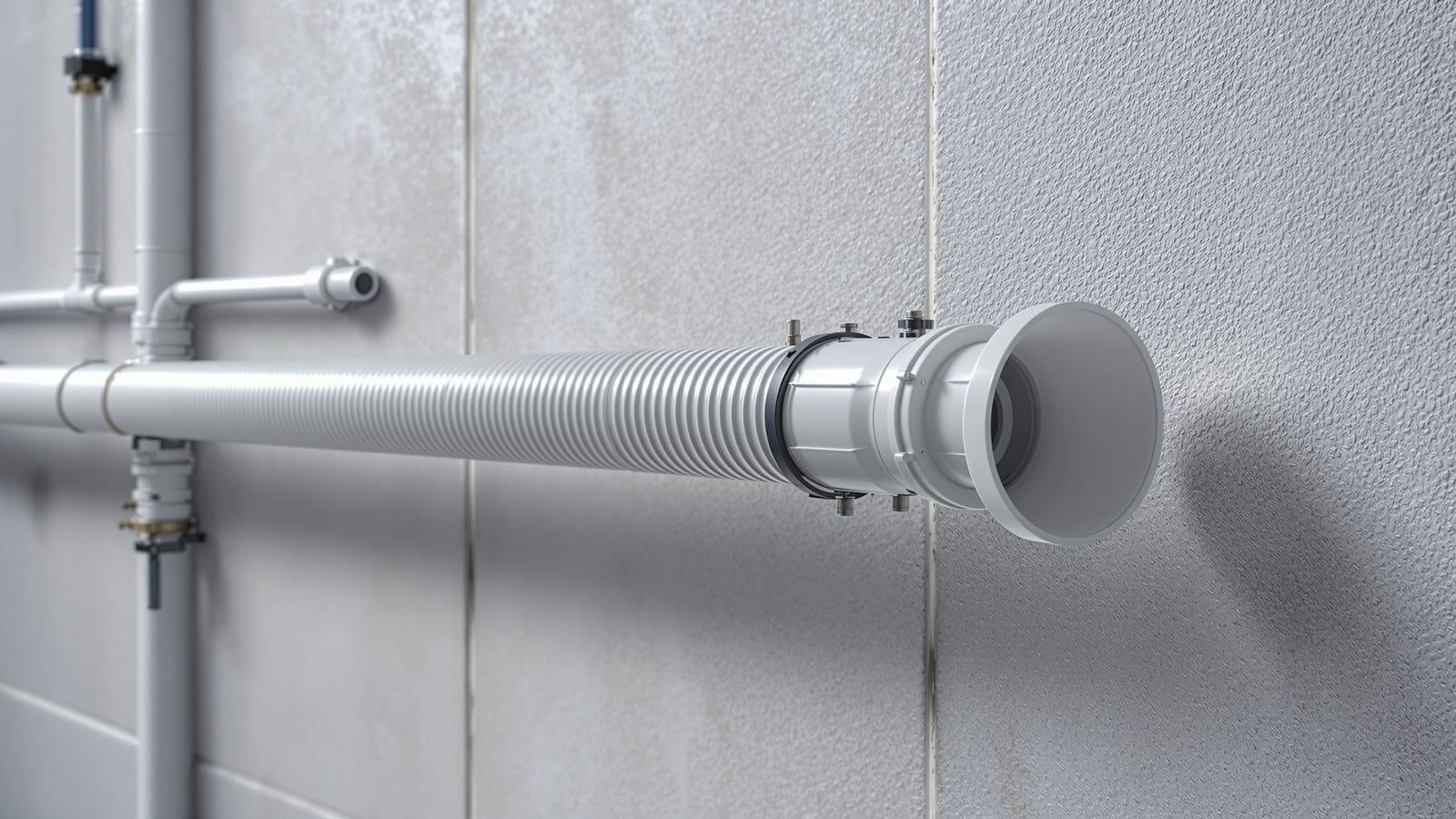
- Expansion joint / bellows. A manufactured fitting — a sliding-sleeve joint or a flexible bellows — that takes up movement in a compact length where there is no room for a loop. Common on long metal risers and industrial lines; used on plastics where a loop cannot be accommodated.
The critical detail with loops and offsets is that the absorbing leg must be free to flex — it needs a guide, not an anchor, so the pipe can move into it. A loop that is clamped tight at its own corners cannot do its job.
Sizing the absorbing leg
The length of the flexing leg grows with the square root of pipe diameter times the movement it must absorb — a bigger, stiffer pipe moving further needs a longer leg. For CPVC, a common rule of thumb sizes the offset leg from the manufacturer's expansion chart; as an order of magnitude, a 25 mm CPVC pipe absorbing around 25 mm of travel needs an offset leg on the order of 0.5-0.7 m free to flex. Always read the actual figure off the pipe maker's loop-and-offset chart rather than guessing — under-sizing the leg just moves the stress back into the joints.
The fix, part two: anchors, guides and slack
Absorbing devices only work if the support system directs the movement into them. That means distinguishing two very different jobs a clamp can do:
- Anchor (fixed point). A rigid clamp that pins the pipe completely, allowing no movement. Anchors define where expansion is forced to grow away from — typically one anchor is set so the run travels toward a loop, offset or free end.
- Guide. A clamp or sleeve that holds the pipe in line but lets it slide axially. Guides carry the pipe's weight and stop it snaking sideways while still letting it lengthen freely toward the absorbing leg.
Get these backwards and everything fails: too many anchors and the pipe has nowhere to grow; no guides and it snakes and sags. The correct pattern on a long run is one considered anchor, guides along the length that permit slide, and a loop or offset (or free end) for the travel to run into.
Two more practical habits matter on site:
- Leave slack, don't pull tight. Never install plastic pipe stretched drum-tight between fixings, especially hot lines. A little slack — the pipe laid in gently, not forced straight — gives the first millimetres of expansion somewhere benign to go.
- Sleeve through walls and slabs. Where a pipe passes through masonry, run it through a sleeve so it can slide rather than grind and abrade against a hard edge every cycle.
Support spacing that accounts for heat and sag
Plastic softens as it warms, so hot lines need closer support than cold lines of the same pipe, and clips must not be so tight they act as unintended anchors. The indicative horizontal spacings below follow the pattern in Indian manufacturer tables; use the specific maker's chart for the pipe class installed.
| Nominal size | CPVC cold, horizontal (indicative) | CPVC hot ~60 degC (indicative) | Note |
|---|---|---|---|
| 15 mm | ~0.9 m (3 ft) | ~0.6 m (2 ft) | Closest support on hot branches |
| 20 mm | ~1.0 m | ~0.7 m | |
| 25 mm | ~1.1 m | ~0.75 m | |
| 32 mm | ~1.2 m | ~0.8 m | |
| 40-50 mm | ~1.3-1.4 m | ~0.9 m | Larger pipe carries more, still sags hot |
Indicative spacings; reduce further for exposed sun-heated runs. Vertical runs generally tolerate wider spacing than horizontal. Confirm against the manufacturer's support table and the pipe supports guide.
A brief note on metal pipes
Metal moves far less, but it does move — and on long, hot or industrial runs it must still be detailed for. Copper hot risers, GI headers and steel process lines use the same logic: fixed anchors, sliding guides, and a device to absorb travel. On metals the device is more often a manufactured expansion joint — an axial bellows or a sliding-sleeve joint — because a metal loop of adequate size is bulky and rigid. For domestic-scale metal plumbing the movement is usually small enough to be taken up by ordinary directional bends; the discipline matters most on long straight runs and where the pipe is genuinely hot. See the copper and GI pipe profiles for material behaviour.
Testing, inspection and code notes
- Cycle before you close. On a concealed hot run, pressure-test and, where possible, run the system hot at least once before tiling, so any movement-related weep shows while it can still be reached.
- Inspect exposed runs seasonally. Terrace and external CPVC/PVC lines take the harshest day-night cycling; look for new bows between clips, migrating clamps and stressed elbows.
- Do not over-tighten clamps. A guide crushed onto the pipe becomes an accidental anchor and a wear point; it should hold alignment, not grip.
- Follow the maker's chart. Support spacing, loop and offset dimensions and pressure-temperature class all come from the pipe manufacturer's technical manual for the exact product — those govern.
Concealed-versus-exposed routing changes how exposed the pipe is to sun-driven cycling; that trade-off is covered in the Bathrooms hub's concealed vs exposed plumbing comparison and is worth reading alongside this before deciding where a hot or terrace main runs.
Thermal expansion is not an edge case — it is a certainty every plastic pipe faces every day. Detail for it and it stays invisible: the pipe grows a few millimetres into a loop and shrinks back, year after year, joint intact. Ignore it and the same few millimetres, multiplied by thousands of cycles, quietly work a concealed joint apart.
References
- National Building Code of India (NBC) 2016, Part 9 — Plumbing Services — the governing framework for water-supply pipework, supports and installation in Indian buildings.
- Bureau of Indian Standards — the IS codes covering CPVC, PPR and PVC piping systems and their fittings and supports; confirm the current code, edition and pressure-temperature class applicable to your installation with a licensed professional.
- Manufacturer technical manuals — coefficient of linear thermal expansion, expansion-loop and offset sizing charts, and hanger/support spacing tables for the specific pipe class installed. Treat every figure here as indicative and verify locally with a licensed plumber before sizing loops or setting anchors.
Export this guide
Related Guides — Deep-dive reading
Pipe Supports, Clamps & Hangers in India: Spacing, Fixing & Anti-Vibration
The clamps, clevis hangers, riser clamps and channel brackets that hold a plumbing system in place — why support spacing matters, how far apart to fix pipe by material and size, how to support risers versus horizontal runs, how to allow for thermal movement, and how to fix into RCC and masonry.
PlumbingBathroom Plumbing Code India: NBC 2016 Part 9, UPC-I & the IS Standards That Govern Pipework
A professional reference to the codes and standards that govern bathroom plumbing in India — the National Building Code (NBC 2016) Part 9 on Plumbing Services, the Uniform Plumbing Code India (UPC-I), the CPHEEO Manual, and the IS standards for water supply, drainage, trap seals, pipe sizing, slopes and venting — with a caveat to always verify the current code and your local authority.
BathroomsLow-Rise Plumbing Systems in India: Houses, Villas & Buildings up to 4 Storeys
How plumbing is organised for independent houses, villas and low-rise buildings up to about four storeys — the simple overhead-tank gravity model, when a small booster is still worth adding, single- versus multi-floor distribution, and the simpler stack and venting a low building can get away with.
PlumbingRelated Tools — Try Free
Cross-Ventilation Analyzer
Estimate airflow and air changes per hour (ACH) from room size, window areas, layout, and local wind — with NBC 2016 Part 8 compliance check.
Ventilation CalculatorMonsoon-Readiness Checklist
Pre-rain home audit across 9 categories — terrace, drains, waterproofing, electrical, HVAC, pest, vehicles, documents.
Seasonal AuditPlumbing Pressure-Test & Leak Checklist
Pre-closure pressure and leak test — 9 categories, 60+ checkpoints across water supply, drainage, fixtures, waterproofing, hot water, tanks.
Pre-Closure Test