
Lift Controller Systems Explained (India): The Microprocessor Brain, VVVF and Diagnostics
How the microprocessor controller commands the VVVF drive, sequences doors, serves calls, levels the car and runs self-diagnostics — and why its certified safety logic stays independent of any smart-home layer.
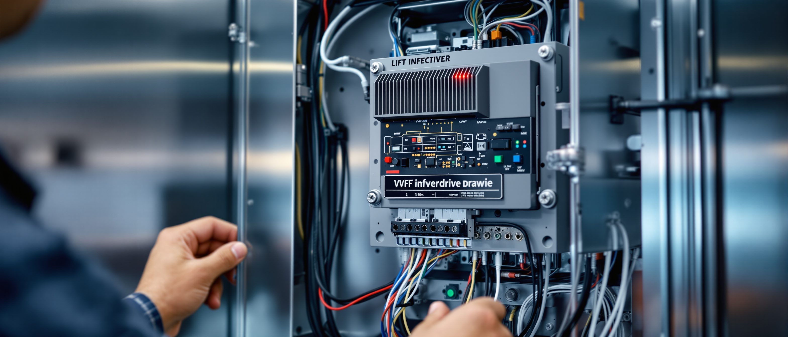
If the motor is the muscle of a home lift, the controller is its brain. Every decision a lift makes in a day — which call to answer first, how fast to accelerate, exactly where to stop so the car floor lines up with your landing, when to nudge the doors open and how long to hold them, what to do when the power fails — is taken by a microprocessor-based controller. It is the least visible part of the lift (it usually lives in a steel cabinet beside or above the hoistway) and the part homeowners understand least, yet it is where reliability, ride comfort and most safety logic actually live.
This is the technical reference for the lift controller system: what the controller does, how it commands the VVVF drive, how it registers and serves calls, how it levels the car, how it diagnoses and logs its own faults, and the difference between a single-lift (simplex) and a multi-lift (group) controller. Crucially, it also explains the principle that matters most for anyone adding smart-home features: the safety-critical control logic is certified and kept independent of any app or automation layer.
For the connected and convenience layers that sit on top of the controller, read Lift Automation Features and Smart-Home Integration for Elevators. For the drive and machine the controller commands, read Lift Motor and Drive Technologies and the plain-language How Home Lifts Work. This guide is the controller-and-diagnostics reference that ties them together.
Specifications and behaviours here are indicative and vary by brand, model and firmware version — always confirm the exact control features and update policy with your vendor before you sign.
What a controller actually is
A modern lift controller is an industrial computer dedicated to one machine. At its core sits a microprocessor (MCU/CPU) running certified firmware, surrounded by:
- Input/output (I/O) boards that read every sensor and switch in the system — landing call buttons, car buttons, door position, the levelling/position sensors, load weighing, limit switches, and every safety contact in the chain.
- A VVVF drive (variable-voltage variable-frequency inverter) that the controller commands to spin the motor exactly as required.
- A door operator interface that drives the automatic door motor and reads its safety edge or light curtain.
- A safety chain — a hard-wired series circuit of every safety device — that the controller monitors but cannot override.
- Power and battery management, including the link to the Automatic Rescue Device (ARD) for power-cut rescue.
- Communication ports — a serial/CAN bus to the car and landing fixtures, and increasingly an Ethernet or cellular link for remote monitoring.
The controller's job is to coordinate all of this in real time, hundreds of times a second, while never letting any convenience feature compromise a safety function.

The core functions, at a glance
The table below is the controller's job description. Each row is a distinct responsibility the brain handles continuously.
| Function | What the controller does | Why it matters to you |
|---|---|---|
| Drive command | Sends speed/torque commands to the VVVF drive and reads motor feedback | Smooth, quiet starts and stops; no jerk |
| Call registration | Reads landing and car buttons; lights the acknowledgement | Your press is recorded reliably |
| Call dispatch (collective control) | Sequences calls in travel order, not press order | Fewer stops, less waiting |
| Floor levelling | Uses position/levelling sensors to stop the car flush with the landing | No trip hazard; wheelchair-safe threshold |
| Door sequencing | Times door open, dwell and close; reverses on the safety edge | Doors that do not nip; correct hold time |
| Safety-chain monitoring | Watches every safety contact; blocks motion if any opens | The lift will not move if a door is unlocked |
| Load management | Reads the overload sensor; refuses to start when overloaded | Prevents straining the machine |
| Standby / energy saving | Powers down lights, fan and idle electronics between trips | Lower running cost |
| ARD / rescue logic | On power failure, drives the car to the nearest floor and opens doors | No one trapped during an outage |
| Self-diagnostics and fault logging | Continuously tests itself; timestamps and stores every fault | Faster, cheaper service calls |
| Remote/IoT reporting | Streams status and faults to the vendor's monitoring platform | Issues spotted before a breakdown |
The remaining sections explain the functions that most affect ride quality, safety and serviceability.
Commanding the VVVF drive
The single biggest contributor to a comfortable ride is how the controller drives the motor. It does this through the VVVF drive — a variable-voltage variable-frequency inverter. Instead of switching the motor hard on and off, the controller computes a smooth speed profile for every trip: a gentle acceleration ramp, a steady run at rated speed, and a precisely shaped deceleration that brings the car to rest exactly at the floor.
The drive works by synthesising an AC waveform of continuously variable voltage and frequency. Lower frequency means lower motor speed; the controller raises and lowers it along the profile while a position feedback device (an encoder on the motor or a shaft position system) tells it where the car is. This closed loop is what gives modern lifts their hallmark smoothness and their accurate stopping — and it is far gentler on the machine, ropes and gearing than older single- or two-speed control.
VVVF control also saves energy, and regenerative drives go further: when the car brakes (a full car going down, an empty car going up), the motor acts as a generator and the drive feeds that energy back into the building's supply instead of burning it off as heat. Combined with a gearless permanent-magnet machine, this is why a modern MRL lift can use markedly less energy than an old geared, relay-controlled installation. The drive hardware and the machine itself are covered in depth in Lift Motor and Drive Technologies; here the point is that the controller owns the speed profile and the levelling.

Accurate floor levelling
Levelling is a controller function people only notice when it is wrong — a car that stops a centimetre high or low creates a trip hazard and is genuinely dangerous for a wheelchair user or someone with a stick. The controller reads the car's position from the levelling/position sensors as it approaches a floor, shapes the final deceleration through the VVVF drive, and holds the car flush with the landing. Good controllers re-level automatically if the car settles under load (common on rope systems as passengers enter). A flush, repeatable stop is one of the clearest signs of a well-tuned controller and drive.
Registering and serving calls: collective control
When you press a button, two things happen: the call is registered (recorded and acknowledged with a lit button) and then dispatched (scheduled into the lift's route). The dispatch logic in almost every modern lift is collective control, which serves calls in the order the car will physically reach them rather than the order they were pressed.
- Down collective is the classic home/low-rise scheme: the car answers car calls and landing-down calls on its way down, sweeping the building efficiently.
- Full collective (selective) handles separate up and down landing calls and is used where there is meaningful two-way traffic.
The practical effect is fewer, smarter stops and less waiting. For a single home lift this is mostly invisible, but the same logic scales up: in a building with two or more lifts, group control coordinates the cars so the nearest suitable one answers each call and the lifts do not all bunch at the same floor.
Collective control is convenience logic, not safety logic. However the controller schedules calls, the safety chain still governs whether the car is allowed to move.
Standby and energy management
Between trips a lift is mostly idle, and a good controller treats idle time as an opportunity to save power. Standby logic dims or switches off the car lighting, stops the ventilation fan, and powers down non-essential electronics and fixtures after a set period, then wakes everything instantly on the next call. On MRL systems the controller also manages the brake and machine to minimise standby draw. For a home lift that may make only a handful of trips an hour, standby management is a meaningful share of the annual running cost.
Self-diagnostics and fault logging
This is the function that quietly saves you money. A modern controller does not just react to faults — it continuously tests itself and the lift around it, and it keeps a time-stamped log of everything that happens.
Continuously, the controller checks that sensors report sane values, that the safety chain is intact, that the drive and door operator respond as commanded, and that communication with the car and landings is healthy. When something is wrong — a door that failed to lock, a levelling sensor that disagreed with the encoder, a drive over-temperature, an ARD battery that tested weak — the controller records a fault code with a timestamp and the lift's state at that moment, takes the safe action (typically holding the car at a floor with doors open), and where appropriate retries or recovers automatically.
That log is what a technician reads on arrival. Instead of guessing, they pull the fault history, see exactly which device failed and when, and fix the cause rather than the symptom. It turns long diagnostic visits into short, targeted ones, which is the single biggest reason fault logging matters for your maintenance bills. (For how that connects to your Annual Maintenance Contract, see the cost and contract sides in the Residential Elevator Buyer's Guide and Home Lift Cost in India 2026.)

Feeding remote and IoT monitoring
The same fault log increasingly leaves the building. Through a network module, the controller streams status and fault events to the vendor's remote monitoring / IoT platform. This enables condition-based maintenance: the service company can see a battery weakening or a door operator drawing more current than it should and act before the lift fails. This connected layer — and what data leaves your home — is the subject of Smart-Home Integration for Elevators and the convenience features in Lift Automation Features. The diagnostics and reporting belong to the certified controller; the apps and integrations sit outside it.
Simplex versus group control
How many lifts the controller manages defines its job:
- Simplex — a single lift, which is the norm in homes. One controller serves one car. Its collective logic simply sweeps its own building.
- Group / duplex / triplex control — two or more lifts coordinated together. The controllers share call information so the most suitable car answers each landing call, lifts spread out across the building instead of bunching, and the group can shed lifts into standby in quiet periods to save energy. This is rare in a single home but standard in apartment cores and the kind of provision a designer makes when planning a building with more than one lift.
For the home segment, you will almost always specify a simplex controller; understanding group control matters mainly when you are reading specifications for a multi-lift building.

The safety principle: certified logic, independent of the smart layer
This is the most important idea in the whole guide. A lift contains two kinds of control that must never be confused.
Safety-critical logic — the safety chain, door interlocks, overspeed and motion-blocking logic, the ARD trigger — is certified and built to recognised safety standards. It is hard-wired and firmware-locked, designed so that any single fault leaves the lift in a safe state (fail-safe). It is not exposed to apps, automation, or any third-party integration, and you cannot reconfigure it from a phone.
Convenience and automation logic — call scheduling, smart-home commands, remote calling, scene control — sits in a separate layer on top. It can request that the lift do something, but it can only ever ask through the controller, which still enforces every safety rule. If the smart layer fails, is hacked, or is switched off, the lift remains a fully functional, fully safe lift.
The smart-home layer can call the lift. It can never overrule the safety chain. Convenience is layered on top of certified safety; it is never wired into it.
Two consequences follow for owners and specifiers:
1. Firmware is updated by the vendor. Because the safety logic is certified, you do not patch it yourself the way you would a phone app. Updates come from the manufacturer through their service process, which preserves the certification. Treat any product that lets a homeowner flash safety firmware over an app with suspicion.
2. Adding smart features should not touch the safety controller. A properly engineered integration talks to a gateway that requests actions from the controller; it does not splice into the safety chain. When you read Smart-Home Integration for Elevators, this is the boundary to insist on.
Standards alignment
Lift control and safety in India sit within a clear standards framework:
- IS 14665 (Electric Traction Lifts) — the core Indian code, aligned to the EN 81 family. Part 3 covers safety rules and Part 4 covers components (the safety gear, governors, buffers and interlocks the controller monitors). The controller's behaviour is constrained by these rules.
- IS 15259 — the companion code for hydraulic lifts.
- IS 17900 — a newer Indian safety standard that aligns home/lift safety with the current European concept of EN 81-20 / EN 81-50. This is the modern reference for safety components and the safety relationship the controller must enforce.
- EN 81-20 / EN 81-50 — the European design and verification standards that IS 17900 follows; the basis of the fail-safe, certified-logic principle described above.
- NBC 2016, Part 8 (Building Services), Section 5 — governs the installation of lifts in buildings in India, alongside the relevant state lift Act where one applies.
Standards numbers and triggers are indicative and are periodically revised — confirm the current applicable standards and your state's lift regulations with a licensed lift contractor.
What this means when you specify a lift
You will rarely choose a controller by part number, but you should ask the right questions:
- Confirm the lift uses a microprocessor VVVF controller with closed-loop levelling, not an old relay/two-speed system.
- Ask whether it supports self-diagnostics with a readable fault log and remote monitoring — this directly shortens service calls.
- For a multi-lift project, confirm group control.
- Confirm the ARD is integrated into the controller's rescue logic, which is essential given Indian power cuts.
- Get the vendor's firmware-update and certification policy in writing, and confirm any smart-home integration sits outside the safety controller.
Pair these with the broader Lift Specification Checklist, and read the component catalogue in Elevator Safety Components and the power-cut procedure in Emergency Rescue Systems for Home Lifts for the devices the controller watches over.
References
Standards referenced (cite by name; confirm current editions with a licensed lift contractor):
- IS 14665 — Electric Traction Lifts (BIS, committee ETD 25; aligned to EN 81): Part 3 (Safety rules) and Part 4 (Components — buffers, guide rails, carframe, safety gears and governors).
- IS 15259 — Hydraulic Lifts (companion code for hydraulic installations).
- IS 17900 — Indian lift safety standard aligned to EN 81-20 / EN 81-50 (current European safety concept) for safety components and controllers.
- NBC 2016, Part 8 (Building Services), Section 5 — Installation of Lifts, Escalators and Moving Walks.
Source URLs:
- IS 14665 Part 1 (BIS): https://law.resource.org/pub/in/bis/S05/is.14665.1.2000.pdf
- IS 14665 Part 2 (BIS): https://law.resource.org/pub/in/bis/S05/is.14665.2.1-2.2000.pdf
- BIS National Building Code 2016: https://www.bis.gov.in/standards/technical-department/national-building-code/
- BIS Guide for Using NBC 2016: https://www.bis.gov.in/wp-content/uploads/2022/08/Booklet-Guide-for-Using-NBC-2016.pdf
- Elevator World — elevator safety components: https://elevatorworld.com/article/elevator-safety-components/
- 99acres — lift regulations in India: https://www.99acres.com/articles/know-all-about-the-lift-regulations-in-india.html
Export this guide
Related Guides — Deep-dive reading
Elevator Safety Components Guide (India): Governor, Safety Gear, Buffers and Interlocks
A plain-language catalogue of the layered safety devices that keep a home lift safe — the overspeed governor and safety gear, buffers, door interlocks, limit switches and more — referenced to IS 14665 Part 4 and IS 17900 / EN 81-20/50.
Home Lifts & AccessibilityPower Failure Safety in Elevators (India): What Happens and What to Do
A power cut does not drop the car. Here is exactly what happens, why an ARD is non-negotiable in India, and how to protect the controller so your lift restarts safely.
Home Lifts & AccessibilityLift Motor Technologies Explained (India): Geared, Gearless PMSM, Hydraulic and VVVF
A component-level reference to lift machines and drives — geared traction, gearless permanent-magnet, hydraulic pump motors, and VVVF and regenerative drive control for Indian homes.
Home Lifts & AccessibilityRelated Tools — Try Free
Lift Safety Audit Checklist
Interactive checklist that scores your home lift on safety devices, compliance and upkeep.
ChecklistLift Annual Maintenance Cost Calculator
AMC cost for a home lift — comprehensive vs non-comprehensive, with a 5-year projection.
Lift CalculatorHome Accessibility Planner
Integrate lift, ramp, stairlift and wheelchair circulation into one accessibility plan.
Planner