

Reinforcement Drawings Simplified
The steel inside the concrete — how to read bar diameters and spacing, the bar bending schedule, main bars and stirrups, cover, laps and the symbols that look like a foreign language until they don't.
Picture a concrete beam in your half-built house. From the outside it is a solid grey rectangle — nothing to see. But inside that grey, before the concrete was ever poured, a cage of steel rods was tied together by hand: long bars running the length of the beam, smaller loops wrapped around them every few inches, the whole thing held a finger's width away from the shuttering. Concrete is enormously strong in compression but weak in tension; steel is the opposite. The two together make reinforced cement concrete — RCC — the material your entire house is built from.
The reinforcement drawing is the recipe for that hidden cage. It is the sheet the bar-bender works from at six in the morning, deciding how many rods, how thick, how long, and how to bend them. To an untrained eye it is the most alien sheet in the whole set — a thicket of numbers like 4-16Ø and 8Ø @ 150 c/c, little symbols that look like a foreign script. They are not. Once you learn to read three or four notations, the entire language opens up.
A reinforcement (RCC detailing) drawing shows the size, number, spacing, shape and position of every steel bar hidden inside a concrete member, so that the steel cage can be cut, bent and tied exactly as the structural engineer designed it.
This guide is for the homeowner who wants to understand why the steel on site matters and how to sanity-check it, and for the B.Arch or civil student and junior site engineer who needs the detailing layer underneath. It assumes you have already met the members the steel goes into — read Understanding Column Layout Drawings, Beam Layout Drawings Explained and Roof & Floor Slab Drawings Explained first if a column mark or beam size is still unfamiliar. The pillar that ties the whole set together is the Construction Drawings Masterclass.
Concrete is the muscle. Steel is the tendon. The reinforcement drawing tells you exactly where the tendons run — and on a hidden material, the drawing is the only witness you will ever have.
1. Why steel goes inside concrete at all
Before the symbols, the why. Drop a plain concrete beam across two supports and load it: it cracks on the underside and snaps, almost without warning. That underside is in tension — being stretched — and concrete simply cannot be stretched. So we bury steel bars exactly where the stretching happens, low down at midspan, and the steel takes the pull while the concrete takes the push on top.
This is the single idea behind every reinforcement drawing. Wherever a member is pulled, you will find steel. That is why beam bottom bars run along the bottom at midspan but climb to the top over the supports (the pull flips there), why a slab has a mesh of bars near its underside, and why a column — pushed from above but also bent by wind and earthquake — has bars running up all four corners.

Everything on a reinforcement sheet ends up as the work in the photograph above: bars cut, bent, laid in position and tied at every crossing with thin binding wire, until the whole cage is rigid enough to hold its shape while concrete flows around it. The drawing is the instruction; this is the result, and it is the last moment anyone can check the steel before it disappears for the life of the building.
In India this is governed chiefly by IS 456 (Plain & Reinforced Concrete — Code of Practice), the parent RCC code. Detailing of the bars follows SP 34 (Handbook on Concrete Reinforcement & Detailing) and IS 2502 (bending and fixing of bars), and in earthquake zones the ductile rules of IS 13920 add closer-spaced loops and longer anchorages so the frame bends rather than shatters. You do not need to memorise these. You need to know they exist, and that the numbers on your sheet come from them.
For students & site engineers: the design itself comes from limit-state analysis to IS 456 — the engineer computes the bending moment and shear at each section, converts moment to a required area of steel (Ast), then chooses a practical bar combination that meets or exceeds it. The drawing you read is the output of that calculation, rounded to real bar sizes. Reading detailing well means reading back from the bars to the forces they answer.
2. Reading a bar callout — the whole language in two lines
Almost every number on a reinforcement sheet is one of two callouts. Learn these two and you can read 90 percent of the drawing.

The first kind counts discrete bars. 4-16Ø reads as four bars, sixteen millimetres in diameter. The dash separates the number of bars from their thickness; the Ø symbol simply means diameter (you will also see it written 16 mm Ø, or T16 / Y16 where T or Y denotes high-yield deformed steel). These are the big load-carrying bars — the main bars.
The second kind describes a repeating set. 8Ø @ 150 c/c reads as eight-millimetre bars, repeated at 150 millimetres centre to centre — meaning the centre of one bar to the centre of the next is 150 mm. The @ means at; c/c means centre-to-centre. This notation is used for stirrups in a beam, ties in a column, and the distribution steel in a slab — anything that repeats at a regular pitch.
| Callout on the sheet | How to read it | What it usually is |
|---|---|---|
| 4-16Ø | 4 bars of 16 mm diameter | Main longitudinal bars |
| 2-12Ø (top) | 2 bars of 12 mm at top | Anchor / hanger bars |
| 8Ø @ 150 c/c | 8 mm bars at 150 mm centre-to-centre | Stirrups or links |
| 8Ø @ 100 c/c near supports | Closer pitch at the ends | Extra shear steel (often IS 13920) |
| 10Ø @ 200 c/c B/W | 10 mm at 200 mm both ways | Slab mesh, bottom |
A practical rule of thumb: bigger diameter and fewer bars means a main load path; small diameter at a stated spacing means a repeating wrap or mesh. Treat every number on these drawings as indicative — the actual sizes for your house must be taken only from your stamped, project-specific reinforcement sheets, never from a guide.
3. Inside a beam — main bars, stirrups and the cage
Now put the callouts onto a real member. A beam cage has three jobs to do, and three families of steel that do them.

The bottom bars carry the tension at midspan, where the beam sags. The top bars carry tension over the supports, where the beam hogs, and also hold the cage together — so you will often see more steel at the bottom in the middle and more at the top near the columns. Wrapping around both, the stirrups (also called links or rings) are the small closed loops at, say, 8Ø @ 150 c/c. They resist shear — the diagonal tearing force that is fiercest near the supports — and hold the main bars in position while concrete is poured. That is why you see stirrups bunched closer together near the ends (8Ø @ 100 c/c) and spread out in the middle: the shear is highest where the beam meets the column.
| Steel in a beam | Sits where | Resists | Typical callout style |
|---|---|---|---|
| Bottom main bars | Lower face, midspan | Sagging tension | 4-16Ø |
| Top bars | Upper face, over supports | Hogging tension | 2-12Ø or extra over supports |
| Stirrups / links | Wrapping the cage | Shear, plus holding bars | 8Ø @ 150 c/c |
| Extra / curtailed bars | Added only where needed | Peak moment zones | 2-16Ø extra top at support |
For students & site engineers: in a ductile frame to IS 13920 the stirrup spacing near a beam-column joint is tightened (the confining zone, typically over a length about twice the beam depth from the face of the support), and stirrup ends are bent back into the core with 135° hooks rather than 90°, so the loop cannot spring open under reversal. On the column, the same logic gives closely-spaced ties at top and bottom — the plastic hinge regions. Spotting whether the detailer has provided this confinement is one of the fastest reads of whether a drawing is seismic-aware. Confirm the exact spacing and hook against the stamped sheet; the values here are indicative.
A column uses the very same two families of steel — main bars plus ties — but arranges them for a different force. Because a column is pushed (and bent both ways by wind and earthquake), its main bars run the full height up every corner, while a beam is bent, so its main steel chases whichever face is in tension. The comparison below puts the two side by side.

4. Cover, lap and development — the three lengths that protect the steel
Three lengths appear again and again on reinforcement drawings, and all three exist to make sure the steel actually does its job. They are the most common things to get wrong on site, so they are worth understanding.

Clear cover is the thickness of concrete between the steel and the outer surface of the member. It is what stops air and water reaching the steel and rusting it, and it gives fire protection. It is small but vital: too little cover and the steel corrodes, the concrete spalls, and the member fails years early. The bar-bender controls it with little cover blocks (cement or plastic spacers) that hold the cage off the shuttering.
Lap length is how far two bars must overlap when one length of steel is not long enough and a second is spliced on. The overlap, tied tightly, lets the load transfer from one bar to the next through the surrounding concrete. Laps are staggered — not all in the same plane — and kept away from the points of highest stress.
Development length (or anchorage length) is how far a bar must extend into a support to be properly gripped by the concrete before it is allowed to stop. A bar that ends too soon simply pulls out. This is why beam bars run into the column and hook, and why slab bars carry into the beam.
The hook at the end of a bar is what does the final gripping, and it comes in two standard angles. A 90° bend is the everyday hook that anchors a main bar into a support; a 135° hook is the tighter fold required for stirrup and tie ends in earthquake zones, because — unlike a 90° hook — it bends back into the concrete core and cannot spring open when the frame is shaken back and forth. The detail below shows both, and shows what a properly anchored bar looks like versus one stopped dangerously short.

| Term | Plain meaning | Typical indicative value (verify on your sheet) |
|---|---|---|
| Clear cover | Concrete shielding the steel | Slab ≈ 15-20 mm; beam ≈ 25 mm; column ≈ 40 mm; footing ≈ 50-75 mm |
| Lap length | Overlap to splice two bars | Often around 45-60 times bar diameter in tension (grade-dependent) |
| Development length | Anchorage into a support | Similar order to lap; set by bar size, grade & concrete |
These values come from IS 456 (cover) and from bond provisions (lap and development), and they change with the concrete grade, the steel grade and the exposure condition. Treat every figure above as indicative only — your engineer's stamped sheet sets the real numbers for your house. A red flag worth knowing: if you see cover blocks missing and steel resting directly on the shuttering, or laps all bunched at midspan of a beam, those are reasons to call your engineer before the pour.
5. The bar bending schedule — turning a drawing into steel you can order
A reinforcement drawing shows where the bars go. The bar bending schedule (BBS) is the table that lists every bar so it can be cut, bent, counted and weighed. It is how steel is quantified and ordered, and how the bar-bender knows exactly what to fabricate.

Each row is one bar type. The bar mark is its label (a01, a02…), the diameter its thickness, the shape code a standard number — defined in IS 2502 — that says how the bar is bent (straight, L-bent, cranked, a closed stirrup, and so on), usually drawn beside it as a little pictogram with the lengths of each leg. From the shape and legs the cutting length is worked out (the straight length of rod to cut before bending, including hook and bend allowances). Multiply by the number of such bars, then by the bars' unit weight, and you get the total weight in kilograms — which is what you actually buy steel by.
| Bar mark | Dia (Ø) | Shape code | Cutting length | No. | Weight (kg) |
|---|---|---|---|---|---|
| a01 | 16 | straight | (per detail) | 4 | (computed) |
| a02 | 12 | L-bent | (per detail) | 2 | (computed) |
| s01 | 8 | closed stirrup | (per detail) | (per spacing) | (computed) |
The arithmetic that turns diameter into weight is worth knowing: a bar's weight per metre is its diameter squared, divided by 162, in kilograms. So a 16 mm bar is about 16 × 16 ÷ 162 ≈ 1.58 kg per metre. That single formula lets a site engineer check a steel delivery against the BBS in minutes.
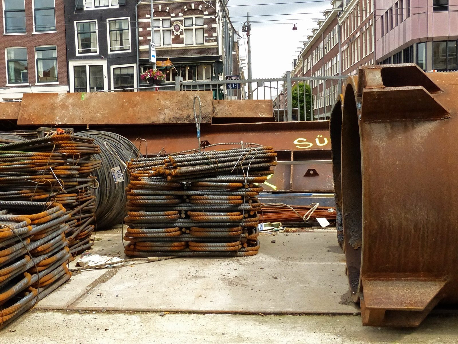
This is what a BBS turns into: bundles of ribbed bars, sorted by diameter, delivered by weight. The ribs you can see on the bars are not decorative — they are the deformations that let the steel bond to concrete, which is exactly what makes the cover, lap and development lengths of the previous section work.
For students & site engineers: the shape codes and the standard hook and bend allowances (a 90° bend, a 135° hook, the minimum mandrel diameter for each bar size) come from IS 2502 and SP 34. Cutting length is not the same as the dimensioned length on the drawing — you add hooks, subtract for bends — and getting this right is the difference between a BBS that orders the correct tonnage and one that wastes steel or runs short. The values and codes here are indicative; always work from the issued schedule.
6. How to use this
You now have the four reads that decode almost any reinforcement sheet: the two callouts (4-16Ø and 8Ø @ 150 c/c), the anatomy of a beam cage (main bars, top bars, stirrups), the three protective lengths (cover, lap, development), and the BBS that turns it all into orderable steel. You are not being asked to design the steel — only to recognise what the drawing is telling the bar-bender, and to spot the obvious red flags before a pour you can never undo.
Take this back to the pillar, the Construction Drawings Masterclass, to see how the reinforcement sheet sits within the full structural set. Run your set through the Construction Drawing Review Checklist before any concrete is ordered, and learn the marks it shares with other sheets in 50 Construction Drawing Symbols Every Homeowner Should Know. When you are ready to commission a structure you can trust, find a registered architect or structural engineer — reinforcement is precisely the place where a licensed professional earns their fee.
Image credits
- Photograph (a worker tying steel reinforcement bars into a cage before concreting): U.S. Navy photo — Public domain, via Wikimedia Commons. Source: https://commons.wikimedia.org/wiki/File:US_Navy_070723-F-8678B-072_Builder_1st_Class_Phillip_Brewer_ties_a_reinforcement_bar_into_the_concrete_roof_of_the_mechanical_shop_project_at_Orote_Point_Quarry.jpg
- Photograph (bundles of ribbed reinforcement bars stacked on a construction site): Fons Heijnsbroek — CC0, via Wikimedia Commons. Source: https://commons.wikimedia.org/wiki/File:2013.06_-_%27Street_still-life_of_piles_of_reinforcement_bars%27,_in_concrete_and_iron_struts_at_the_metro_construction_Vijzelgracht_in_Amsterdam;_urban_photography_in_the_Netherlands,_Fons_Heijnsbroek_(10351027425).jpg
References & Further Reading
Indian standards & manuals
- IS 456 — Plain & Reinforced Concrete, Code of Practice (the parent RCC code; cover and bond/anchorage).
- SP 34 — Handbook on Concrete Reinforcement & Detailing (the detailing companion to IS 456).
- IS 2502 — Code of Practice for Bending & Fixing of Bars for Concrete Reinforcement (shape codes, hooks, bends, the basis of the BBS).
- IS 13920 — Ductile Detailing of Reinforced Concrete Structures Subjected to Seismic Forces (confinement, hooks, hinge regions).
- IS 1786 — High Strength Deformed Steel Bars & Wires for Concrete Reinforcement (the Fe 500 / Fe 550 grades you will see specified).
- National Building Code of India (NBC) 2016, Part 6 (Structural Design).
Books / references
- P. C. Varghese, Limit State Design of Reinforced Concrete.
- S. Unnikrishna Pillai & Devdas Menon, Reinforced Concrete Design.
- A. K. Jain, Reinforced Concrete: Limit State Design.
- B. C. Punmia, Reinforced Cement Concrete Structures.
Companion Studio Matrx guides
- Construction Drawings Masterclass — the pillar overview of the whole set.
- Understanding Column Layout Drawings and Beam Layout Drawings Explained — the members this steel goes into.
- Roof & Floor Slab Drawings Explained — slab mesh and distribution steel.
- Construction Drawing Review Checklist — the pre-pour red-flag walkthrough.
Author's Note — Amogh N P: I have watched a bar-bender, who could not read English, fabricate a flawless beam cage from nothing but a reinforcement detail and a BBS, bending each rod to a shape code he knew by heart. That sheet is a contract between an engineer who will never visit the site and a craftsman who will never read the calculations — and it works because the language is precise. Learn to read it, even a little, and the most opaque part of your house becomes the most honest.
Disclaimer: This guide is an educational overview to help you read reinforcement drawings; it is not a substitute for a licensed structural engineer or registered architect. Steel design and detailing must be carried out by a qualified professional. All sizes, spacings, covers, laps and other values mentioned here are indicative and typical only — act solely on the stamped, project-specific drawings and bar bending schedule issued for your building.
Export this guide
Related Guides — Deep-dive reading
Beam Layout Drawings Explained
How the beams that carry your slabs are drawn — beam marks, sizes, the difference between a beam you can see and one hidden in the slab, and why beams must land on columns.
Construction DrawingsConstruction Quality Control for Homeowners
How to make sure your house is actually built well, stage by stage, without an engineering degree — concrete, steel, cover and curing, the cardinal site sins to refuse, and the simple checks anyone can do.
Structural SafetyRoof Sagging & Structural Warning Signs: When to Call an Engineer Now
The structural red-flag guide for Indian roofs. Which signs are just maintenance and which mean stop, photograph, and call a structural engineer today — sagging slabs, diagonal cracks, spalling concrete with rusting steel, jamming top-floor doors, and a leaning parapet, explained plainly.
RoofingRelated Tools — Try Free
Cross-Ventilation Analyzer
Estimate airflow and air changes per hour (ACH) from room size, window areas, layout, and local wind — with NBC 2016 Part 8 compliance check.
Ventilation CalculatorApartment Furniture Size Chart
Standard furniture dimensions for Indian apartments — sofas, beds, tables, dining, storage.
Reference ChartConcept Generator
Get 3 AI-generated design concepts for any room with style, materials, and cost estimate.
DesignAI