

Foundation Drawings Explained
What is under your house — isolated footings, combined footings, rafts and piles, how to read a footing plan and schedule, and how the soil report decides which one you get.
A mason once told me the unkindest thing a building can do is sink at one corner. Everything above — the doors that no longer close, the staircase that twists, the hairline crack walking up a wall — is the house quietly reporting that the ground gave way somewhere you never see. He pointed at the soil and said, only half joking, that this is the one part of your home you build blind and trust forever.
The drawing that decides whether you can trust it is the foundation drawing. It is usually one of the first sheets your structural engineer issues and one of the last you would think to read, because nothing on it is glamorous — no kitchen island, no façade, just squares and lines buried under your floor. Yet this sheet is the contract between your whole house and the earth under it.
Spend ten minutes with it now and you will understand the single most expensive thing on site to get wrong.
A foundation drawing is the plan and schedule that show where every footing sits, how big and deep it is, what steel goes inside it, and how the footings are tied together — so that the entire weight of your house is spread onto soil that can carry it without sinking.
This guide is written first for the homeowner holding a footing plan they cannot read, and then taken to real depth for B.Arch and civil students and junior site engineers. It sits inside our Construction Drawings Masterclass pillar. The footing plan starts where the column layout ends — every footing is born under a column — so read that first. It also speaks to the beam layout guide, because the plinth beam is a beam, and to the reinforcement guide, because what is inside a footing is steel.
Your house is only ever as honest as the soil it stands on — and the foundation drawing is where that honesty is negotiated.
1. Why the foundation exists: spreading load onto soil
Every load in your house — slab, beam, wall, the people and furniture inside — travels down the columns as a concentrated push. A column is slender; if it simply sat on the ground, that push would punch into the soil like a stiletto heel into wet earth. The footing is the broad shoe at the bottom of that heel. It takes the column's concentrated load and spreads it over a wide patch of soil, so the pressure on the ground drops to something the soil can quietly bear.
That is the whole idea, and it is governed in India by IS 1904 (Code of Practice for Design and Construction of Foundations in Soils — General Requirements), the umbrella foundation code. Its aim, in plain words, is to size the footing so the pressure reaching the soil never exceeds what the soil can safely take, and to keep settlement small and even.
For students & site engineers: IS 1904 sets the general requirements — site investigation, allowable bearing pressure, permissible total and differential settlement, the shallow-versus-deep decision — and hands detailed structural design to IS 456 for the RCC and to the geotechnical investigation for the ground. The footing is proportioned in plan so net soil pressure stays within the safe bearing capacity, then designed in thickness so concrete and steel stresses stay within permissible limits.
2. The five footing types you will meet
Foundations split into two families: shallow ones that rest on competent soil near the surface, and deep ones that reach down to firm strata far below. Your drawing will name which type you have. Here are the five you are most likely to see on an Indian house.

| Footing type | What it looks like | When it is used (indicative) |
|---|---|---|
| Isolated / pad | A separate square or rectangular pad under each single column | The default for most G+1 / G+2 homes on decent soil |
| Combined | One footing carrying two columns that are too close to have separate pads | Columns near a boundary, or two columns close together |
| Strip | A continuous strip of concrete running under a wall or a row of columns | Load-bearing wall construction; closely spaced columns |
| Raft / mat | One thick slab under the entire building footprint | Weak soil, or when isolated footings would nearly touch |
| Pile | Columns of concrete reaching down to firm strata, with a pile cap on top | Soft, filled or high-water-table sites where surface soil cannot carry |
Isolated, combined and strip footings are shallow foundations. Raft is shallow but spreads load over the whole footprint. Piles are a deep foundation — they bypass weak surface soil entirely and transfer load to a firm layer metres down. Bored piles are common in Indian cities because they avoid the noise of driven piles.
The two you are most likely to choose between on a house are isolated footings and a raft. They start from the very same column grid and answer the same question — how to carry the load — in opposite ways.

The footing type is not a style choice. It is the soil's verdict, written into your drawing.
3. How the soil report decides which one you get
You do not pick a footing type from a catalogue; the ground picks it for you. The deciding number is the safe bearing capacity (SBC) — how much pressure, in kilonewtons per square metre (kN/m2), the soil can safely carry. A soil investigation (boreholes, or a plate load test) measures it before the structural engineer designs anything.

The logic is simple. Pressure equals load divided by area. If the soil is firm and its SBC is high, a small footing area is enough. If the soil is weak and its SBC is low, you need a much larger footing area to keep pressure within limits — and if it gets too large to be practical, you switch to a raft or go down to piles.
As an indicative band only, many residential G+1 / G+2 buildings are designed on soils with an SBC of roughly 100 to 200 kN/m2; your project's value comes from your soil report, never from a guide. SBC also falls sharply when the water table is high or the soil is black cotton (expansive) — both common in parts of India — which is why the same house needs different foundations in different towns.
Size is only half the story; depth is the other half. The same soil report that sets the footing area also sets the founding depth — how far below ground level the footing must sit. A footing is deliberately taken down past the loose fill, the topsoil and the seasonal-moisture zone, so it bears on steady ground that does not compress, rot or swell with the monsoon.

For students & site engineers: SBC on the drawing is the net safe bearing capacity at founding level, already factored down from ultimate capacity and checked against permissible settlement. Watch for black cotton soil (treated by going below the active zone, or by under-reamed piles) and for a seasonally high water table, which can reduce effective bearing pressure substantially. The founding depth itself is set so the footing sits below loose fill, topsoil and the zone of seasonal moisture movement.
Red flag
If your structural drawings carry no soil report reference and no stated SBC, pause. A footing schedule that was not derived from a known SBC is a guess. Ask your engineer for the geotechnical report the design is based on.
4. Reading the footing plan and the footing schedule together
Like the column layout, a foundation drawing is two halves that must be read as one: the footing plan (where, in plan, each footing sits) and the footing schedule (the table that gives each footing its real size, depth and steel). The plan shows you position; the schedule is the source of truth for dimensions.

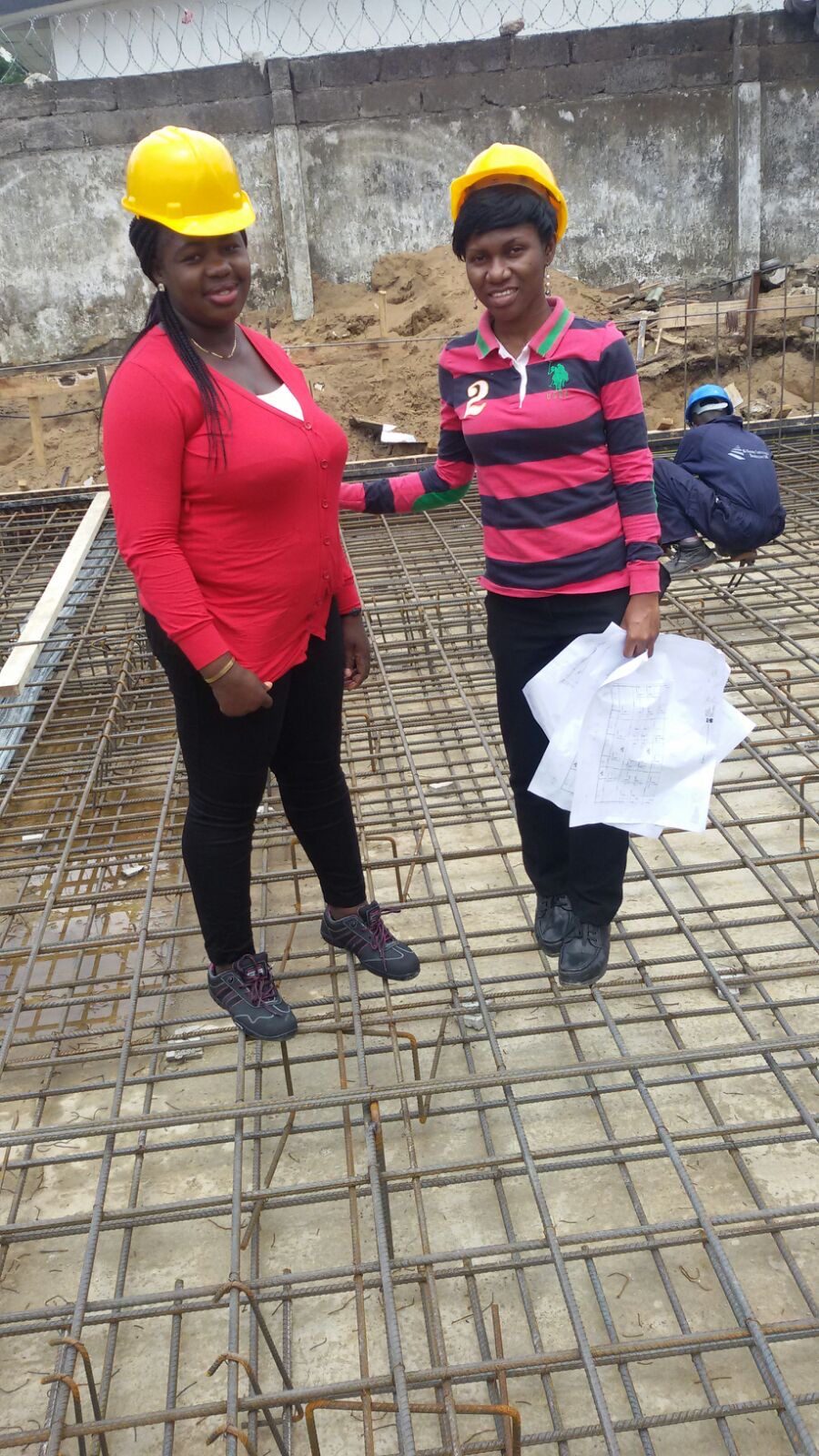
The reinforcement called up in the schedule does not stay on paper — it is tied into a steel mat and laid in the excavation before any concrete is poured, exactly as the drawing in hand specifies. On the plan, each footing is drawn as a square or rectangle centred on its column, sitting on the same lettered-and-numbered structural grid you met in the column layout. Each footing carries a mark — F1, F2, F3 — exactly as columns carry C1, C2. Footings that are identical share a mark, so the plan can stay clean and the schedule can describe each type once.
The schedule then expands every mark:
| Mark | Footing size (indicative) | Depth below GL (indicative) | Supports column | Reinforcement (indicative) |
|---|---|---|---|---|
| F1 | 1500 x 1500 | 1.5 m | C1, C4 | 12Ø @ 150 c/c both ways |
| F2 | 1800 x 1800 | 1.5 m | C2, C3 | 12Ø @ 125 c/c both ways |
| F3 | 1200 x 2400 | 1.5 m | C5 (combined) | as detail |
Every number above is illustrative only — read your own values off the stamped schedule and footing details, never off a guide. The golden rule, borrowed straight from professional practice: never size a footing from the plan drawing alone. The plan shows representative shapes; the actual dimensions and steel live in the schedule and the section details it references.
Do / don't
- Do cross-check that every footing mark on the plan has a matching row in the schedule, and that every column has a footing under it.
- Don't accept a plan whose footings overlap or run off the plot boundary — overlapping isolated footings are a sign the engineer should have combined them or moved to a raft.
5. The plinth beam, the DPC, and where your house begins
If footings are the feet, the plinth beam is the belt that ties them together at ground level. It is an RCC beam running between footings (and between columns just above them), drawn on or alongside the foundation sheet. Its job is to knit all the footings into one connected frame so they settle together rather than independently, to carry the ground-floor walls, and — importantly in India's seismic zones — to brace the column bases against sideways movement in an earthquake.

Resting on or just above the plinth beam, your drawing will show the damp-proof course (DPC) — a thin horizontal waterproofing layer that stops ground moisture from wicking up into your walls by capillary action. Above the DPC, the house is dry; below it lives the foundation. This line is, in a real sense, where the superstructure your house begins. The plinth level itself is the finished level of the ground floor, raised above the surrounding ground so rain does not run in.
For students & site engineers: the plinth beam reduces the effective length and slenderness of columns by connecting them near ground level, which materially improves the building's seismic behaviour — it is not optional decoration in a seismic zone. The DPC is commonly a rich cement-concrete band (often around 40 mm) with an integral waterproofing compound, or a cement-mortar layer; treat any thickness or mix quoted here as indicative and confirm from the project specification and the relevant damp-proofing practice.
Red flag
No plinth beam shown, footings simply sitting under columns with nothing tying them, on a normal framed house in a seismic region — query it. So should the absence of any DPC line, which invites rising damp into every ground-floor wall.
6. How to use this drawing
Treat the foundation drawing as the first sheet you sign off and the last you compromise on, because it is the only one already buried by the time anything goes wrong. Run three checks: does every column have a footing of a size that traces back to a stated SBC and soil report; does every footing mark on the plan appear in the schedule; and are the footings tied together by plinth beams above a clear DPC line.
When you have read it, walk back up the structure: return to the Construction Drawings Masterclass to see how the foundation hands off to columns and slabs, and take the drawing review checklist to site so nothing is skipped before the first pour. If you are still choosing how to build, our building a house in India guide sets the sequence, you can generate and explore plans on DesignAI, and you can find an architect or browse ready house plans to start from.
Image credits
- Photograph (engineers on a tied steel reinforcement mat before concreting): OLUWATOBILOBA — CC BY-SA 4.0, via Wikimedia Commons. Source: https://commons.wikimedia.org/wiki/File:Female_Structural_Engineers.jpg
References & Further Reading
Indian standards & manuals
- IS 1904 — Code of Practice for Design and Construction of Foundations in Soils: General Requirements (the umbrella foundation code).
- IS 456 — Plain and Reinforced Concrete, Code of Practice (RCC design of footings and plinth beams).
- IS 1080 and the soil-investigation codes — for site investigation and shallow-foundation design.
- Damp-proofing practice (general building damp-proofing) — for the DPC layer.
- NBC 2016 (National Building Code of India) — overall building requirements and the foundation context.
Books / references
- B. C. Punmia, Soil Mechanics and Foundations.
- N. Krishna Raju, Reinforced Concrete Design (for footing and plinth-beam detailing).
- SP 34 — Handbook on Concrete Reinforcement and Detailing, and IS 2502 — Bending and Fixing of Bars for Concrete Reinforcement (for the steel inside footings).
Companion Studio Matrx guides
- Understanding Column Layout Drawings — where every footing is born.
- Beam Layout Drawings Explained — the plinth beam is a beam.
- Reinforcement Drawings Simplified — the steel inside a footing.
- Construction Drawing Review Checklist — what to check before you pour.
Author's Note — I have stood in too many excavated pits at dusk, watching a site engineer chalk a footing outline onto raw earth, to ever treat this sheet casually. The foundation is the one act of faith in building a house: you cover it, you finish the home above it, and you spend years trusting a drawing you can no longer see. I wrote this so that you can read that drawing once, clearly, while it still matters. — Amogh N P
Disclaimer: This is an educational overview to help you read foundation drawings, not a substitute for a licensed structural engineer, a geotechnical consultant or a registered architect. All sizes, depths, SBC values, reinforcement and DPC details here are indicative and typical only; act solely on the stamped, project-specific soil report and drawings prepared for your site.
Export this guide
Related Guides — Deep-dive reading
Beam Layout Drawings Explained
How the beams that carry your slabs are drawn — beam marks, sizes, the difference between a beam you can see and one hidden in the slab, and why beams must land on columns.
Construction DrawingsWhy Buildings Leak: Tracing the Paths Water Takes Into Your Home
The four sources of water in a building — rain, plumbing, ground and condensation — why the stain is never where the leak is, and the homeowner's method for tracing a leak to its true source before spending a rupee.
Structural SafetyHow Architects Read Drawings Differently Than Homeowners
The same sheet, two different readings — what a trained eye notices first, the questions professionals ask of a drawing, and how to start seeing a plan the way your architect does.
Construction DrawingsRelated Tools — Try Free
Material Schedule Generator
Generate a room-wise finish schedule — walls, floors, ceilings, trim, and joinery by location.
Material ScheduleMonsoon-Readiness Checklist
Pre-rain home audit across 9 categories — terrace, drains, waterproofing, electrical, HVAC, pest, vehicles, documents.
Seasonal AuditApartment Furniture Size Chart
Standard furniture dimensions for Indian apartments — sofas, beds, tables, dining, storage.
Reference Chart