

Understanding Drawing Scales
Why a 9-metre wall is 18 centimetres on paper — how ratio scales work, the scales used for each kind of sheet, the scale bar, and how to measure (and never to trust a scaled-off dimension over a written one).
Imagine you are standing in front of your half-built house. The longest wall of the living room runs nine metres, end to end — longer than a car, taller than two people if you stood it up. Now the architect hands you a sheet of A1 paper and points to a clean rectangle on it. That same nine-metre wall is sitting there in front of you as a line just eighteen centimetres long. You could cover it with your palm.
Nothing has shrunk. The wall is still nine metres. The paper has simply agreed to a deal: every measurement on it has been reduced by the same fixed amount, so that the whole house fits on a sheet you can roll up and carry. That agreed reduction — that fixed shrink ratio — is called the scale.
Once you understand scale, a drawing stops being a confusing tangle of lines and becomes a faithful, measurable map of your real building. Misunderstand it, and you can argue for an hour about whether a door is "too small" when in fact you were reading a sheet drawn at half the zoom you thought.
A drawing scale is the fixed ratio between a length drawn on paper and the real length it represents, written as 1:100, 1:50 and so on — the bridge that lets a whole building live on a single sheet without losing its true proportions.
This guide is for the homeowner who has just been handed a drawing set and wants to measure off it with confidence, and for the B.Arch or civil student who needs the conventions stated correctly. It pairs naturally with the pillar guide Construction Drawings Masterclass, with 50 Construction Drawing Symbols Every Homeowner Should Know, and with the Construction Drawing Review Checklist you will run before any concrete is poured.
Scale tells you how much the world was shrunk. The written dimension tells you the truth. When they disagree, the writing wins.
1. What a scale ratio actually means
A scale is written as two numbers with a colon, such as 1:100. Read it as "one to one hundred". It means: one unit of length on the paper stands for one hundred of the same units in the real building. The unit can be anything — a millimetre, a centimetre, an inch — as long as both sides use the same one. One millimetre on paper is one hundred millimetres on site. One centimetre on paper is one hundred centimetres on site.
So at 1:100, a real wall of 9 metres (9000 mm) is drawn at 9000 ÷ 100 = 90 mm, which is 9 cm. At 1:50 the same wall is drawn twice as big: 9000 ÷ 50 = 180 mm, or 18 cm — the eighteen centimetres from our opening. Notice the rule hiding here: the bigger the second number, the smaller the drawing, because you are dividing by more. 1:500 is very "zoomed out"; 1:5 is very "zoomed in".

In India, drawings follow IS 962, the Bureau of Indian Standards code of practice for architectural and building drawings. It recommends a standard family of scales — full size 1:1, and reduction scales 1:2, 1:5, 1:10, 1:20, 1:50, 1:100, 1:200, 1:500, 1:1000 and larger (down to 1:10000) — and it asks that dimensions normally be written in millimetres. Sticking to this family means any architect, contractor or engineer reading the sheet knows the convention instantly.
A worked conversion, both ways
Suppose you measure a bedroom on a floor plan with an ordinary ruler and get 30 mm across, and the title block says the scale is 1:100. To find the real size, multiply by the scale number: 30 mm x 100 = 3000 mm = 3.0 metres. That is your real bedroom width.
Going the other way: your architect tells you a verandah is 4.2 m (4200 mm) deep and you want to know how long that line should be on a 1:50 sheet. Divide by the scale number: 4200 ÷ 50 = 84 mm. So on the paper, the verandah depth is an 84 mm line. Multiply when going from paper to reality; divide when going from reality to paper. That single sentence is the whole arithmetic of scale.

Seeing the same wall stacked at 1:50, 1:100 and 1:200 makes the pattern obvious: the line on paper halves each time you double the scale number, while the real 9000 mm wall never moves. That is the whole idea in one picture — the world is fixed, the paper is what gets shrunk.
For students & site engineers: the ratio is dimensionless, which is why it works regardless of unit. Formally, drawn length = real length ÷ scale factor, and the representative fraction (RF) for 1:100 is simply 1/100. When you set out on site you do the reverse of reading: you take figured dimensions, not scaled ones — more on that in Section 4.
2. Which scale belongs on which sheet
Different sheets answer different questions, so they are drawn at different scales. A site plan must fit the whole plot and its surroundings, so it is heavily reduced. A construction detail must show a 10 mm gap clearly, so it is barely reduced at all. The scale always matches the level of detail the sheet is meant to carry.

| Sheet type | Typical scale (indicative) | What it lets you see |
|---|---|---|
| Site / layout plan | 1:500 to 1:200 | The plot, setbacks, the building footprint, roads |
| Floor plans | 1:100 (1:50 for small homes) | Rooms, walls, doors, fixtures, overall dimensions |
| Elevations | 1:100 or 1:50 | The face of the building, heights, openings |
| Sections | 1:50 | The building sliced through — floor-to-floor heights, slab, plinth |
| Large-scale plans (kitchen, toilet) | 1:50 to 1:20 | Tile setting-out, fixture positions |
| Construction details | 1:20 to 1:5 (or 1:1) | A junction, a chajja, a waterproofing layer |
These are the common conventions, not rigid rules — a large bungalow plan might be drawn at 1:100 while a compact flat is at 1:50 so it fills the sheet. Always read the actual scale from the title block of the sheet in your hand. A single sheet can even carry more than one scale: the main plan at 1:100 and an enlarged toilet detail at 1:20 in a corner, each with its own scale noted directly beneath it. Never assume one sheet means one scale.
Red flag: if a drawing has no scale stated anywhere — not in the title block, not under the view, and no scale bar — you cannot reliably measure anything off it. Treat it as a sketch, not a working drawing, and ask for a properly titled sheet.
3. The scale bar — the ruler that survives the photocopier
There is a quiet problem with the stated ratio. The moment a drawing is photocopied "to fit", emailed and printed at the wrong paper size, or scaled on a screen, the paper shrinks or stretches — but the printed "1:100" note does not change. Now the note lies: the sheet says 1:100 but a metre no longer measures what it should. This is one of the most common ways homeowners get fooled.
The cure is the graphic scale bar: a short ruled bar printed on the drawing itself, divided into labelled lengths — 0, 1 m, 2 m, 5 m. Because the bar is printed as part of the drawing, when the whole sheet is reduced to 75%, the bar reduces by exactly 75% too. It always stays true to the lines around it, whatever happens to the paper. You measure against the bar, not against an assumed ratio.

To use it: set the zero of the bar against one end of the line you want to measure, then read where the other end falls on the bar. A pair of dividers, or even the edge of a strip of paper marked with two pencil ticks, transfers the distance perfectly. Architects also use a proper scale rule (a triangular ruler with 1:100, 1:50 and other faces) — but only on an original, full-size print; on any copy of unknown size, the printed bar is the only honest reference.
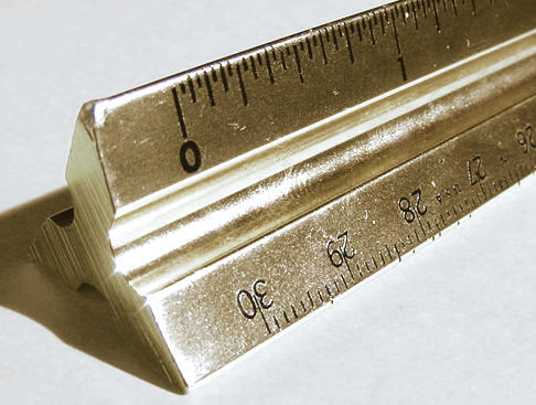
A scale rule packs several scales onto one instrument so the architect can read or draw at 1:50, 1:100 and others without arithmetic — the triangular cross-section above carries a different graduated scale along each of its six edges.
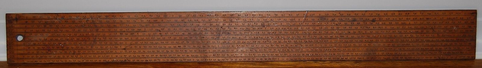
Older flat scale rules crowd many scales side by side along a single wooden strip. Whichever form it takes, the rule is only trustworthy on an original, full-size print — feed it a photocopy of unknown size and it will read a confident, wrong number.
For students & site engineers: this is why many professional and tender drawings carry the explicit note "DO NOT SCALE — WORK TO FIGURED DIMENSIONS", often alongside a graphic bar for rough field reference only. The note is a formal acknowledgement that paper is an unreliable measuring medium. It pushes everyone toward the written numbers, which brings us to the single most important rule in this guide.
4. The cardinal rule: the written dimension always wins
Every working drawing carries two kinds of length. One you can measure with a ruler off the paper — a scaled dimension. The other is written on the drawing as a number against a dimension line — a figured, or written, dimension. When the two disagree, the written dimension is correct and the scaled one is wrong. Always. No exceptions.
There are good reasons. The written number is what the designer actually intended and what the engineer designed to; the scaled length is only as accurate as the printer, the paper and your ruler. Drawings get reduced, lines have thickness, and a half-millimetre of ruler error at 1:100 is 50 mm — a finger's width of real wall — at 1:50 it is still 25 mm. You would never set out a door opening by scaling it.

The worked example above shows exactly how the disagreement plays out on a copied sheet: scaling the shrunken wall gives 3800 mm, but the written 3000 mm is the truth. Trust the writing, every time.
| Situation | What to trust | Why |
|---|---|---|
| A wall has a written dimension (3000) | The written 3000 mm | It is the designer's true intent |
| Two written dimensions exist but do not add up | Neither — query the architect | The sheet has an error to fix |
| No written dimension, only a scale bar | The scale bar, as approximate only | Better than the stated ratio on a copy |
| No dimension and no scale bar | Nothing — request a proper drawing | The sheet is not measurable |
So scaling has its place — it is wonderful for a quick sense of size, for checking a room "feels" right, for spotting an obvious mistake. But the instant a number matters — setting out a footing, cutting a beam, ordering a kitchen counter — you read the figured dimension, and if it is missing, you ask for it. A drawing that forces the site to scale critical lengths is an incomplete drawing.
Do: measure roughly off the scale bar to understand a space. Don't: ever build, cut or order from a scaled length when a written one is missing — get it added.
5. How to use this
Start every sheet the way a professional does: find the scale in the title block first, glance for a scale bar, and only then begin reading the lines — now you know exactly how much the world was shrunk. Use scaling to understand and sanity-check, and the written dimensions to build. If a sheet has no scale, no bar and no figured dimensions on the wall you care about, that is your cue to call the architect, not your contractor's tape.
From here, go back to the Construction Drawings Masterclass pillar to see how scale fits with the title block, grid and levels; learn the marks themselves in 50 Construction Drawing Symbols Every Homeowner Should Know; and when your set is in hand, run the Construction Drawing Review Checklist before any pour. If you do not yet have a drawing set, you can explore ready layouts at /house-plans, generate design options with DesignAI, or find an architect to draw and stamp your set.
Image credits
- Photograph (metal triangular architect's scale rule): User CatherineMunro on en.wikipedia — CC BY-SA 3.0, via Wikimedia Commons. Source: https://commons.wikimedia.org/wiki/File:Architects_scale.jpg
- Photograph (flat wooden draughtsman's scale rule with many engraved scales): ElliotCaspar — CC BY-SA 4.0, via Wikimedia Commons. Source: https://commons.wikimedia.org/wiki/File:Pre-1840_Architects_Scale_Rule_image_1_of_4.jpg
References & Further Reading
Indian standards & manuals
- IS 962:1989 — Code of Practice for Architectural and Building Drawings (Bureau of Indian Standards): recommended scale family, sheet sizes, line work and dimensioning in millimetres.
- National Building Code of India (NBC) 2016 — general drawing and documentation practice for building submissions.
Books / references
- M. Chakraborti, Building Construction (drawing and detailing conventions in Indian practice).
- Francis D. K. Ching, Architectural Graphics — scale, dimensioning and drawing standards.
- B. P. Verma, Civil Engineering Drawing and House Planning — drawing standards and scale practice.
Companion Studio Matrx guides
- Construction Drawings Masterclass
- How Architects Read Drawings Differently Than Homeowners
- 50 Construction Drawing Symbols Every Homeowner Should Know
- Construction Drawing Review Checklist
Author's Note — Amogh N P: The first time I watched a homeowner argue with a contractor on site, both were right and both were wrong: she had scaled a photocopied plan, he had read the written number, and the two were 40 mm apart. I have loved scale ever since for its honesty — it asks only that you read the ratio, trust the writing, and never let a shrunk piece of paper tell you a lie about your own house.
Disclaimer: This guide is an educational overview to help you read drawing scales with confidence. It is not a substitute for a licensed structural engineer, MEP consultant or registered architect. Always act on stamped, project-specific drawings, take critical lengths from written (figured) dimensions, and treat every scale, value and convention here as indicative only.
Export this guide
Related Guides — Deep-dive reading
How Architects Read Drawings Differently Than Homeowners
The same sheet, two different readings — what a trained eye notices first, the questions professionals ask of a drawing, and how to start seeing a plan the way your architect does.
Construction DrawingsConstruction Drawings Masterclass: How to Read Your Home's Working Drawings
The complete homeowner's field guide to the drawing set that builds your house — architectural, structural, plumbing, electrical and HVAC sheets, what each one is for, the symbols and scales that decode them, and how to review them before you pour a single footing.
Construction DrawingsSmall Bathroom Layout India: 3x5, 4x6 & 5x7 ft Plans That Actually Work
How to plan a tiny Indian bathroom so it feels bigger and works harder — the best fixture arrangements for 3x5, 4x6 and 5x7 ft rooms, corner basins, sliding doors, wall-hung sanitaryware, clearances in mm and rupee-smart tricks.
BathroomsRelated Tools — Try Free
Interior Layout Planner — Printable Graph Grid
Printable graph grid to sketch room layouts to scale before committing to furniture placement.
Layout ToolAI Measurement Tool
Measure your room using voice, photos, or video sweep — no tape measure needed.
DesignAICross-Ventilation Analyzer
Estimate airflow and air changes per hour (ACH) from room size, window areas, layout, and local wind — with NBC 2016 Part 8 compliance check.
Ventilation Calculator