
CCTV Network Diagram for India (2026): Mapping Cameras, Switches and Storage
A ready-to-adapt CCTV network diagram that maps IP cameras to PoE switches, up to the NVR and storage, with a segregated camera VLAN, a firewall for remote access and an IP addressing scheme — so the network is buildable, secure and supportable.
A cctv network diagram is the drawing that shows how the whole system actually connects: every IP camera to its PoE switch, each switch up to the core and the recorder, the NVR or server and its storage, the router or firewall, any remote or cloud link, and how the camera network is kept separate from the main LAN. It is the difference between a set of cameras and a network someone can build, secure and support.
This is a design deliverable. It is drawn from the camera schedule and the network schedule once the device count and locations are settled, and it is used three ways: by the installer to build the cabling and switching, by a cyber reviewer to check segregation and the firewall boundary, and by whoever inherits the system to troubleshoot and extend it. It sits alongside the broader security system architecture diagram, which shows all the security subsystems at a higher level; the network diagram zooms into the CCTV data path.
Scope and how to read this. This is a ready-to-adapt professional template, not authoritative, contractual or vendor-specific wording. Addressing is shown as a scheme to assign per project, never as fabricated live IP addresses or model numbers. Get a qualified network and security review for your actual project, and defer specifics to your equipment, your site and your organisation policy.
What a good CCTV network diagram shows
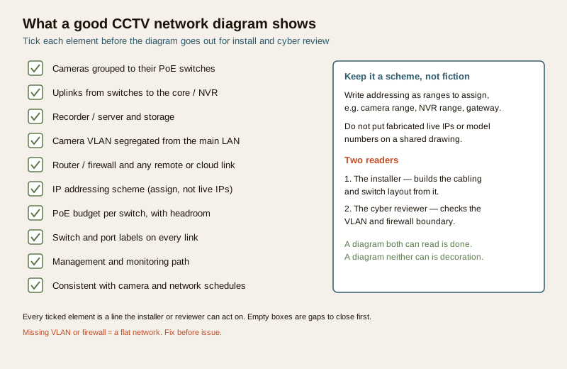
A diagram that only draws boxes and lines is decoration. A useful one lets the installer wire it and the reviewer defend it. It should show, clearly and in words:
- Cameras grouped to their PoE switches. Each camera or camera group connected to the switch that powers and carries it, so cable runs and port counts are obvious.
- Uplinks to the core or NVR. How each edge switch reaches the core switch and the recorder, and whether uplinks are single or resilient.
- The recorder or server and its storage. The NVR or VMS server and where recordings land, with retention shown as "days: verify" rather than a fabricated number.
- The segregated camera VLAN. The camera network drawn as its own VLAN, visibly separate from the office or main LAN. This is the single most important cyber-security line on the drawing.
- Router or firewall and any remote or cloud access. The boundary device, and any path out to a remote client or cloud service, drawn as passing through the firewall — never a camera wired straight to the internet.
- The IP addressing scheme. Ranges to assign for cameras, the NVR, the gateway and management, shown as a scheme, not live addresses.
- PoE budget per switch, with headroom. A note per switch that the powered devices sit inside the switch budget with margin; work the numbers in the PoE budget guide and reference it, do not invent wattages here.
- Labels and a management path. Switch and port labels on links, plus how the system is managed and monitored.
A worked example diagram
The figure below is a clean, illustrative example: cameras grouped to two PoE switches, both uplinked to a core switch that feeds the NVR and storage, the whole camera side drawn as a segregated VLAN, and a firewall as the only route between the cameras, the office LAN and any remote or cloud access. It carries no live IP addresses and no model numbers — those are assigned per project.
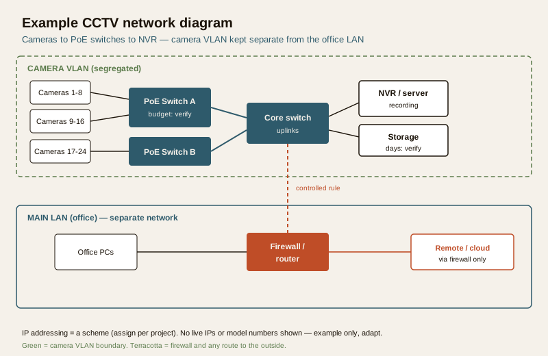
Read it as a data path: a camera powers up on its PoE switch, that switch uplinks to the core, the core delivers the stream to the NVR, and recordings sit on the storage. Everything on the camera side lives inside one VLAN. The only way in or out — office PCs viewing footage, or a remote or cloud client — is through the firewall, on a controlled rule. That one boundary is what makes the network defensible.
What to show: the filled checklist
Use this as the acceptance test for the drawing itself before it is issued. Mark each element done only when it is genuinely on the diagram in a way a reader can act on. This is a filled example — adapt to your project.
| # | Element to show | On the diagram? |
|---|---|---|
| 1 | Cameras grouped to their PoE switches | Done |
| 2 | Uplinks from each switch to core / NVR | Done |
| 3 | Recorder / server and storage (retention: verify) | Done |
| 4 | Camera VLAN drawn separate from main LAN | Done |
| 5 | Router / firewall shown as the boundary | Done |
| 6 | Remote / cloud access via the firewall only | Done |
| 7 | IP addressing shown as a scheme, not live IPs | Done |
| 8 | PoE budget per switch noted (headroom) | Done |
| 9 | Switch and port labels on links | Done |
| 10 | Consistent with camera and network schedules | Done |
Blank checklist to copy
| # | Element to show | On the diagram? |
|---|---|---|
| 1 | Cameras grouped to their PoE switches | ... |
| 2 | Uplinks from each switch to core / NVR | ... |
| 3 | Recorder / server and storage | ... |
| 4 | Camera VLAN separate from main LAN | ... |
| 5 | Router / firewall as boundary | ... |
| 6 | Remote / cloud access via firewall only | ... |
| 7 | IP addressing scheme (assign) | ... |
| 8 | PoE budget per switch (headroom) | ... |
| 9 | Switch and port labels | ... |
| 10 | Consistent with the schedules | ... |
The IP and device list
The diagram is easier to read and to build when a short companion table lists every device, what it is, the address to assign, and where it plugs in. Keep the address column as a scheme — a range to assign, or a placeholder — rather than committing live addresses to a shared drawing. This is a filled example; the values are illustrative only, adapt to your project.
| Device | Type | IP / range (assign) | Switch / port | VLAN |
|---|---|---|---|---|
| Camera C-01 | Dome IP camera | Camera range, assign | Switch A / P1 | Camera VLAN |
| Camera C-08 | Bullet IP camera | Camera range, assign | Switch A / P8 | Camera VLAN |
| Camera C-20 | PTZ IP camera | Camera range, assign | Switch B / P4 | Camera VLAN |
| PoE Switch A | Edge switch | Mgmt range, assign | Core / uplink 1 | Camera VLAN |
| PoE Switch B | Edge switch | Mgmt range, assign | Core / uplink 2 | Camera VLAN |
| NVR-01 | Recorder / server | NVR range, assign | Core / P1 | Camera VLAN |
| Firewall | Boundary / router | Gateway, assign | Core / P24 | Inter-VLAN |
Blank IP and device list to copy
| Device | Type | IP / range (assign) | Switch / port | VLAN |
|---|---|---|---|---|
| ... | ... | ... | ... | ... |
| ... | ... | ... | ... | ... |
| ... | ... | ... | ... | ... |
Field guide
- Segregate the camera VLAN. Draw the camera network as its own VLAN, separate from the office or main LAN, every time. This is best practice and the first thing a cyber reviewer looks for; see network segmentation for IoT for the reasoning.
- Plan the addressing and document it. Decide the ranges — cameras, NVR, management, gateway — as a scheme, put them in the device list, and keep them out of the drawing as live addresses. Undocumented addressing is the reason a system nobody can log into ends up being rebuilt.
- Give PoE headroom. Note per switch that the powered load sits comfortably inside the switch budget, with margin for a future camera. Work the actual figures in the PoE budget guide; do not guess wattages on the diagram.
- Label switches and ports. A link with no label is a guess on install day. Label the switch and the port at each end so the cabling matches the drawing.
- Firewall the remote access. Any path to a remote client or cloud service goes through the firewall on a defined rule. No camera or recorder is ever drawn straight to the internet; treat that as a red line, reinforced in the CCTV cyber-security guide.
- Keep it consistent with the schedules. The diagram must agree with the camera schedule and the network schedule — same device count, same names, same locations. When one changes, change the others.
Common mistakes
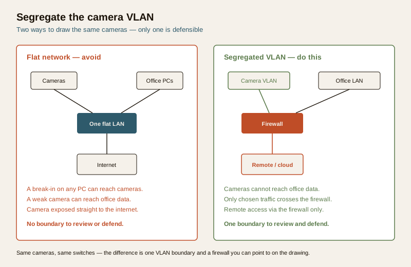
- A flat network with the office LAN. Cameras and office PCs on one flat network means a break-in on any PC can reach the cameras, and a weak camera can reach office data. Draw the VLAN.
- No segregation shown at all. If the diagram cannot show where the camera network ends and the LAN begins, there is no boundary to review or defend.
- Exhausted PoE. Loading a switch to its limit with no headroom means the next camera will not power up. Note the budget and leave margin.
- Undocumented IPs. Addresses that live only in someone memory turn into a rebuild the day that person leaves. Capture the scheme in the device list.
- A camera exposed to the internet. A recorder or camera reachable directly from outside is the classic breach. Route everything through the firewall.
How it connects
The network diagram is one document in a set, and it is only right when it agrees with its neighbours:
- The camera schedule fixes how many cameras there are and where; the diagram groups those cameras onto switches.
- The PoE budget guide sizes the power per switch that the diagram then annotates.
- Network segmentation for IoT and the CCTV cyber-security guide set the VLAN-and-firewall thinking the diagram makes visible.
- The security system architecture diagram sits above it, showing CCTV alongside the other subsystems.
Find the full set of practitioner deliverables in the professional security resources library and its resources hub.
A note on data. CCTV records identifiable people, so the network that carries and stores it holds personal data under the Digital Personal Data Protection Act, 2023. Segregation, a firewall boundary and controlled remote access are not only good engineering — they are part of handling that data responsibly. Keep the diagram and device list access-controlled, and defer specifics to your organisation policy and legal advice.
Key takeaways
- A CCTV network diagram maps the data path from cameras to switches to the NVR and storage, and it is drawn from the camera and network schedules for install, cyber review and handover.
- Show the essentials: cameras grouped to PoE switches, uplinks to the core, the recorder and storage, a segregated camera VLAN, the firewall and any remote or cloud link, the addressing scheme, PoE budget per switch, and clear labels.
- Segregate the VLAN, document the addressing, firewall the remote access — and keep the drawing consistent with the schedules.
- Use the what-to-show checklist and the IP and device list as the reusable artifacts; copy the blank versions and adapt them, keeping addresses as a scheme rather than fabricated live IPs.
References
- Digital Personal Data Protection Act, 2023 — CCTV video identifying people is personal data; keep the network, storage and access controlled and purpose-limited.
- Manufacturer documentation for your specific cameras, switches, recorder and firewall — the authoritative source for PoE budgets, addressing, VLAN and firewall configuration; follow it over any generic guidance.
- Bureau of Indian Standards catalogue for any structural, electrical, cabling or life-safety standard referenced in an install; verify the current edition at https://www.services.bis.gov.in/
This is an educational, ready-to-adapt template, not authoritative, contractual or legal advice. Network design, addressing, VLAN and firewall configuration are qualified professional tasks — engage competent network and security professionals, and defer specifics to your project, your equipment and the relevant authority.
Export this guide
Related Guides — Deep-dive reading
CCTV Remote Access in India (2026): Watch From Your Phone, Safely
How to view your own cameras from anywhere without leaving the front door open to the internet — change the defaults, use strong credentials and 2FA, keep firmware current, prefer the vendor's secure cloud relay or a VPN, segment the camera network, and treat footage as personal data.
SecurityCCTV Storage Schedule for India (2026): Sizing Recording to Retention
A ready-to-adapt design document that records, per camera or camera group, the recording settings and the retention target that together drive how much NVR, server or cloud storage the system needs.
SecurityInternet and Network Readiness for Home Security in India
Before you buy a single camera, plan the network under it: enough upload bandwidth for cloud and remote viewing, wired PoE for the cameras that matter, a segregated IoT network so a hacked gadget cannot reach your laptop, and secure remote access that never exposes your DVR to the open internet.
SecurityRelated Tools — Try Free
Security Cabling & PoE Planner
Estimate cable length, drops, PoE power budget, the right switch, conduit and cost for a CCTV/security cabling plan.
Cabling PlannerCCTV Camera Coverage & Count Calculator
Estimate how many CCTV cameras you need, the NVR channels, storage in TB for your retention period, and an indicative all-in cost with GST.
CCTV CalculatorPoE Power-Budget Calculator
Whether a PoE switch can power the connected cameras with cable-loss headroom, and how many devices it supports.
PoE Budget