
Security System Architecture Diagram for India (2026): The One Picture of the Whole System
A ready-to-adapt block diagram that shows every security subsystem, how they integrate, where the head-end and control room sit, and how it all is powered and managed, so the whole project team shares one mental model.
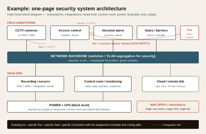
Ask five people on a security project to describe "the system" and you get five different pictures. The camera vendor sees cameras, the IT team sees switches, the fire consultant sees the panel, the client sees an app on a phone. The security system architecture diagram is the one page that puts all of them on the same picture: a single high-level block diagram showing every subsystem, how they connect and integrate, where the recording and control room sit, and how the whole thing is powered and managed. Everyone points at it and means the same thing.
This is the overview drawing that the detailed documents hang off. The network diagram, the equipment schedule and the zoning plan all zoom into a corner of this picture; the integration matrix lists in a table what this diagram shows as lines. It lives in the design stage and travels through design reviews, tender and handover as the shared reference. It is part of Studio Matrx's professional security resources toolkit.
Scope & how to read this. This is a ready-to-adapt professional template, not authoritative or contractual wording, and not a wiring drawing. Use it to build a shared overview; get professional and, where fire and life safety are involved, fire-officer review before it drives a build. Specifics come from your project, the National Building Code (NBC = SP 7:2026), the manufacturer and the authority having jurisdiction (AHJ). Where the diagram touches egress and fire, treat it as life-safety and verify.
What it is and where it sits
A security architecture diagram is deliberately high-level. It is not a cable schematic and not a rack layout; it is the block picture that answers four questions at a glance: which subsystems exist, which of them talk to each other, where the brains and the people sit, and what keeps it alive when something fails. A reader should understand the whole system in under a minute.
It is produced by the security consultant or designer during design and reviewed by the architect, the client or facility team, the IT lead and the fire consultant. In tender it tells bidders the intended shape of the system so their offers are comparable. At handover it becomes the map the operator and the maintenance vendor use. Because it is the anchor, everything else must stay consistent with it as the design develops.
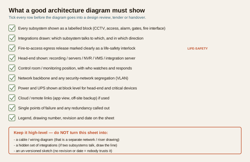
What a good architecture diagram shows
A strong diagram is complete without being cluttered. Aim to show each of the following as a block or a labelled line.
- Subsystem blocks. CCTV, access control, intrusion alarm, gates and barriers, and the fire alarm interface, each a clearly named block.
- Integrations, with direction. The lines that matter, not every cable. Typical ones: alarm to CCTV (an alarm calls up the relevant camera), access to CCTV (a door event tags footage), and fire to access (a fire condition releases egress doors). Draw who triggers whom.
- The head-end. Recording and servers, the NVR or VMS, and any integration or management server that ties subsystems together.
- Control room and monitoring. Where operators watch, the video wall, and how a response is raised. A system nobody watches is a recorder, not security.
- Network backbone and segregation. The switching that carries it, and whether the security network is segregated (for example on its own VLAN) from office and guest networks.
- Power and UPS, at block level. Which blocks sit on backed-up supply. You are not sizing batteries here, only showing that head-end, control room and critical field devices stay up.
- Cloud and remote links. App viewing, remote support and any off-site backup, drawn as an explicit link so it is not a surprise later.
- Single points of failure and redundancy. A single core switch, a single UPS or a single internet link is worth a note, so the team decides on redundancy with eyes open.
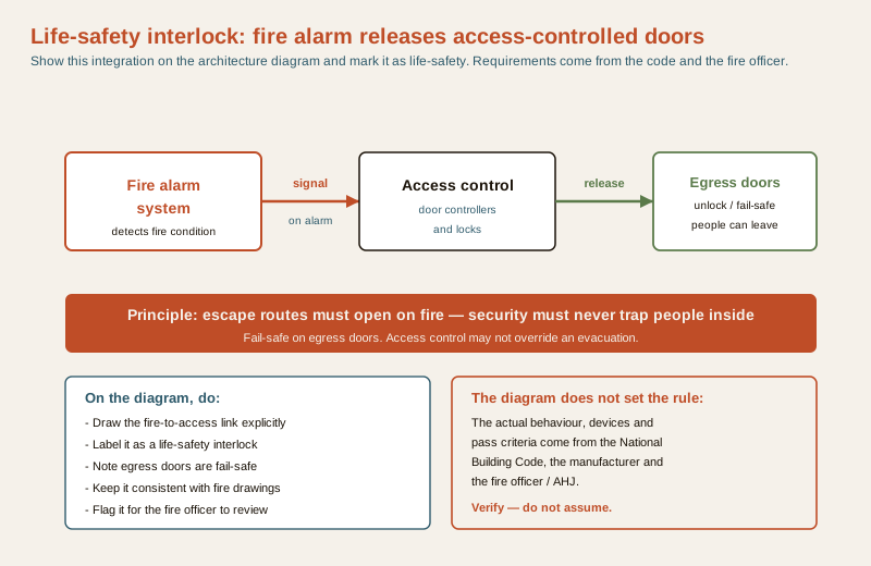
Life-safety interlock. The fire-to-access link is not just another integration. Escape routes must open on a fire condition and security must never trap people inside. Show egress doors as fail-safe, label the link a life-safety interlock, and remember the actual behaviour and pass criteria come from the code, the manufacturer and the fire officer, not from this drawing.
Worked example: a "what to show" checklist, filled
Here is the checklist run against the example diagram in the figure above. Use it to prove a diagram is complete before it goes into a review.
Example only — adapt to your project. Values are illustrative.
| # | Element the diagram must show | On this example diagram | Done |
|---|---|---|---|
| 1 | All subsystem blocks named | CCTV, access, alarm, gates, fire interface all shown | Yes |
| 2 | Integrations drawn with direction | alarm to CCTV, access to CCTV, fire to access | Yes |
| 3 | Fire-to-access egress release marked life-safety | Labelled interlock, egress doors fail-safe | Yes |
| 4 | Head-end shown | Recording or servers plus integration server block | Yes |
| 5 | Control room / monitoring position | Control room block with operator and response | Yes |
| 6 | Network backbone and segregation | Backbone bar, security VLAN noted | Yes |
| 7 | Power and UPS at block level | UPS block feeding head-end and critical devices | Yes |
| 8 | Cloud / remote links | App view and off-site backup link shown | Yes |
| 9 | Single points of failure and redundancy | Single core switch and single link flagged | Yes |
| 10 | Legend, drawing number, revision, date | Title block with drawing no., rev and date | Yes |
Blank template: copy this checklist
Copy the empty checklist below into your review sheet and tick it for each revision of the diagram. It is the core reusable artifact of this page.
| # | Element the diagram must show | Where shown on drawing | Done (Y/N) |
|---|---|---|---|
| 1 | All subsystem blocks named | ... | ... |
| 2 | Integrations drawn with direction | ... | ... |
| 3 | Fire-to-access egress release marked life-safety | ... | ... |
| 4 | Head-end (recording / servers / integration) | ... | ... |
| 5 | Control room / monitoring position | ... | ... |
| 6 | Network backbone and any segregation | ... | ... |
| 7 | Power and UPS at block level | ... | ... |
| 8 | Cloud / remote links (if used) | ... | ... |
| 9 | Single points of failure and redundancy | ... | ... |
| 10 | Legend, drawing number, revision, date | ... | ... |
| ... | ... | ... | ... |
Component and legend list
A diagram is only shared if its symbols are agreed. Keep a small legend on the sheet so a solid line, a dashed line and a highlighted block mean the same to everyone. The table below shows a worked legend followed by blank rows to adapt.
Example only — adapt symbols to your drawing standard.
| Block or item | Symbol / label on drawing | Notes |
|---|---|---|
| CCTV subsystem | Solid box, "CCTV" | Cameras to NVR or VMS |
| Access control | Solid box, "Access" | Readers, controllers, doors |
| Intrusion alarm | Solid box, "Alarm" | Sensors and panel |
| Fire alarm interface | Red-outlined box, "Fire" | Life-safety; interface only, not the full fire design |
| Head-end | Solid box, "Recording / servers" | NVR or VMS plus integration server |
| Control room | Solid box, "Control room" | Operators, video wall, response |
| Network backbone | Shaded bar | Switches; note VLAN segregation |
| Power / UPS | Solid box, "UPS" | Blocks on backed-up supply |
| Cloud / remote | Green-outlined box | App view, off-site backup |
| Integration link | Dashed line, arrowed | Direction shows who triggers whom |
| Life-safety interlock | Bold dashed line, labelled | Fire to access egress release |
| SPOF / redundancy | Callout note | Single switch, single link, single UPS |
| ... | ... | ... |
| ... | ... | ... |
Field guide: getting it right
Keep it high-level. The moment you start drawing individual cables, camera counts or IP addresses, you are building a different document. Blocks and links only; the detail belongs in the network diagram and the equipment schedule.
Show integrations and dependencies, never hide them. If two subsystems exchange a signal, draw the line and arrow it. Hidden integrations are how a project discovers at commissioning that the alarm was meant to call up a camera and never did.
Mark life-safety interlocks. The fire-to-access egress release, and any other interlock affecting escape, must be labelled as life-safety on the drawing. Note that egress doors are fail-safe and that the requirement is set by the code and the fire officer, not by the diagram.
Call out redundancy and single points of failure. Even a one-line note ("single core switch — consider redundancy") turns an invisible risk into a design decision.
Version and date the drawing. A security architecture diagram without a drawing number, revision and date is a sketch nobody trusts. Put a title block on it.
Keep it consistent with the schedules and zoning. When the equipment schedule or the zoning plan changes, update this drawing in the same pass, or the anchor drifts from reality.
Common mistakes
- Turning it into a cable diagram. Too much detail hides the shape of the system. Stay at block level.
- Hiding the integrations. A tidy diagram with no links between subsystems is not integrated, it is just co-located.
- No control room or monitoring. A picture of recorders with no one watching describes storage, not security.
- No version or date. An un-versioned drawing cannot be trusted in a review or a tender.
How it links to the other documents
The architecture diagram is the top of a small family of deliverables, and its value is that they all agree with it:
- The network diagram takes the backbone and head-end blocks and details the switches, links and addressing. See CCTV network diagram.
- The equipment schedule lists, line by line, the devices inside each block. See security equipment schedule.
- The zoning plan shows the same subsystems positioned across the site in security zones. See security zoning plan.
- The integration matrix is this diagram written as a table of who talks to whom. Keep the two in step.
For the wider picture of how these systems fit a building, see the building security systems guide, and browse the full security resources library.
Key takeaways
- The security architecture diagram is the one high-level picture that gives the whole team a shared mental model of the system.
- Show every subsystem block, the integrations with direction, the head-end, the control room, the network and segregation, power and UPS, cloud links and any single points of failure.
- Mark the fire-to-access egress interlock as life-safety, keep egress doors fail-safe, and defer the actual requirements to the code and the fire officer.
- Keep it high-level, versioned and dated, and consistent with the network diagram, equipment schedule and zoning plan.
- Use the what-to-show checklist to prove completeness and the blank template to run every revision.
References
- National Building Code of India (NBC, SP 7:2026) — for fire, egress and life-safety requirements that any fire-to-access interlock must satisfy; the code and the fire officer set the rule, not the drawing.
- Manufacturer documentation for your recorders, controllers and panels — the authoritative source for what each subsystem can integrate and how.
- Bureau of Indian Standards catalogue — verify the current edition of any standard referenced in the design at https://www.services.bis.gov.in/
This is an educational template to adapt, not legal, contractual or life-safety advice. Fire, egress and any electrical work are qualified professional tasks — engage licensed professionals and the fire officer, and get professional and legal review before this diagram drives a build.
Export this guide
Related Guides — Deep-dive reading
Access Control Maintenance in India (2026): Readers, Locks and Fail-Safe Egress
How to keep a card, keypad, fingerprint or face access-control system reading reliably and locking securely — and, above everything, how to test that its doors still release on a fire alarm and on power loss, so an access-controlled door never becomes a life-safety trap.
SecurityAccess Control Testing Checklist for India (2026): Every Door Opens and Locks as Designed
A ready-to-adapt per-door and system checklist to verify an access-control installation at commissioning and as a periodic check, with the egress and fire-to-release life-safety tests that must always pass before sign-off.
SecurityProfessional Security Resources for India (2026): The Documents Behind a Secure Project
The overview and map of the whole professional-deliverable toolkit — the brief, schedules, BOQ, checklists, handover pack and logs a consultant, designer, PMC or facility manager produces across a security project, and how each document connects to the next.
SecurityRelated Tools — Try Free
Emergency-Egress Checker
A life-safety self-check that access-controlled doors on escape routes still let people out in an emergency.
Egress CheckAccess-Control Battery-Backup Calculator
Size the standby battery so an access system keeps running through a power cut, with an egress life-safety note.
Battery BackupCCTV Camera Coverage & Count Calculator
Estimate how many CCTV cameras you need, the NVR channels, storage in TB for your retention period, and an indicative all-in cost with GST.
CCTV Calculator