
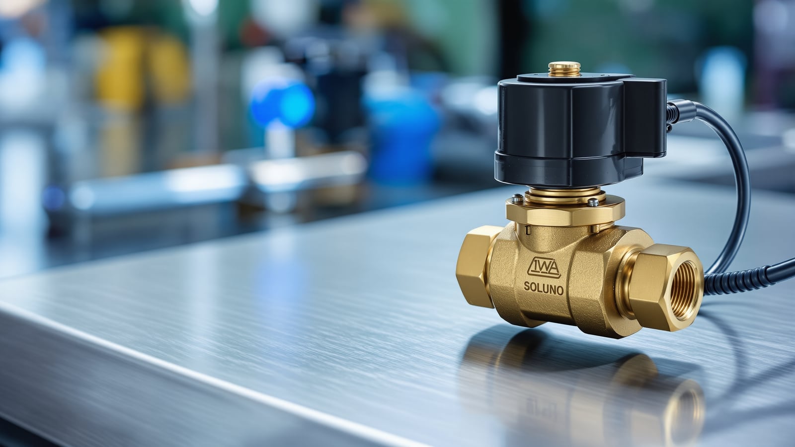
Solenoid Valves in India: How They Work, NC vs NO, Sizing, Voltage & Cost
The electrically operated valve that opens or closes the instant it gets a signal — the building block of every automatic water control. How a solenoid coil actuates the valve, normally-closed vs normally-open, direct-acting vs pilot-operated, 12/24V vs 230V, where it is used in tank filling, irrigation, sensor taps and leak shut-off, plus sizing, fail-safe behaviour and indicative cost in India.
A solenoid valve is a valve that opens or closes when an electric current energises a coil — no hand, no float, no pressure signal, just a wire carrying a switch decision. It is the single component that turns a plumbing line into something a controller, a timer or a sensor can command, which is why it sits underneath almost every "automatic" water function in a modern building.
This is a professional's guide to specifying solenoid valves in Indian water work. It sits under the Studio Matrx plumbing valves guide and is the companion to the mechanical valve guides it so often replaces or backs up — the check valve that stops reverse flow and the float valve that a level-sensor-plus-solenoid arrangement is increasingly used to supersede.
What a solenoid valve is and how the coil actuates it
Strip one down and there are only a few parts: a valve body with an inlet, an outlet and an internal orifice; a movable plunger (armature) with an elastomer seal on its tip; a spring; and a coil wound around the plunger's guide tube.
- De-energised, the spring holds the plunger against (or away from) the orifice — that resting position defines whether the valve is normally-closed or normally-open.
- Energised, current through the coil creates a magnetic field that pulls the ferromagnetic plunger along the tube, compressing the spring and flipping the valve to its other state.
- Switched off, the field collapses and the spring instantly returns the plunger to rest.
That is the whole trick: a coil converts an electrical signal into a few millimetres of plunger travel, and those millimetres open or close a water path. Switching is fast — a fraction of a second — and it is binary: a solenoid valve is an on/off (two-position) device, not a throttling one. To modulate flow you reach for a motorised control or globe valve, not a solenoid.
Normally-closed vs normally-open
The rest state — where the valve sits with no power — is the first thing you specify, because it decides what happens on a power cut and how much energy the valve burns.
- Normally-closed (NC): shut when de-energised, opens only while powered. This is the default for almost all water work. Power fails, the valve shuts and the line is safe — exactly what you want for tank filling, irrigation and leak shut-off.
- Normally-open (NO): open when de-energised, closes only while powered. Used where flow must continue if control power is lost, or where the valve is normally passing water and only occasionally interrupted.
Because most solenoid valves hold their non-rest state only while energised, an NC valve that is open for long stretches — a garden line watering for an hour — is drawing coil current the whole time and warming up. Where a valve must stay in a position for long periods, look for a latching (bi-stable) solenoid that takes a brief pulse to switch and then holds mechanically with no standing current; these are common in battery-powered irrigation and sensor products.
Direct-acting vs pilot-operated
How the plunger opens the main orifice splits solenoid valves into two families, and getting this wrong is the most common specification error in the field.
- Direct-acting: the plunger seals the main orifice itself. The coil must be strong enough to lift against the full line pressure over that orifice, so direct-acting valves are limited to small orifices and low flows — but they will work down to zero pressure differential, which matters when a valve must open on a nearly static line.
- Pilot-operated (servo / diaphragm): the plunger opens only a tiny pilot orifice; line pressure itself then does the heavy work of lifting a diaphragm off the main seat. This lets a small coil control a large valve and high flow — but it needs a minimum pressure differential (often around 0.2–0.5 bar, product-dependent) between inlet and outlet to operate. On a gravity tank with barely any head, a pilot valve may simply refuse to open; there you need a direct-acting or an assisted-lift type.
The trap: a pilot-operated valve specified for an overhead-tank gravity feed with almost no pressure difference will not open reliably. Match the valve family to the available differential pressure, not just the pipe size.
Voltage: 12/24V low-voltage vs 230V mains
The coil can be wound for whatever supply the control system offers, and the choice is as much about safety and wiring as about the valve.
- Low-voltage DC (12V or 24V): the norm for anything driven by electronics — irrigation timers, level controllers, sensor taps, dosing units, leak-detection boards. Extra-low voltage is safe to run in wet locations and near the fixture, and it interfaces directly with sensors and microcontrollers. 24V AC is also common on irrigation controllers.
- 230V AC mains: used where the valve is switched by a simple mains contactor, float-switch or panel and no electronics are involved — a pump-panel interlock, an industrial fill line. It removes the need for a separate transformer but must be wired, earthed and IP-rated for a wet plumbing location by a competent electrician.
For anything a homeowner or occupant can touch, and for every sensor-driven fixture, prefer extra-low voltage (12/24V) behind a proper SMPS/transformer. Reserve 230V coils for enclosed plant rooms and panels.
Where solenoid valves are used
The solenoid valve is the actuator; the intelligence sits in whatever sends it the signal. The common Indian applications:
- Automatic overhead-tank filling. A level sensor or level controller in the tank (float switch, probe or ultrasonic) drives an NC solenoid on the inlet: tank low, coil on, valve fills; tank full, coil off, valve shuts. This is the electronic alternative to a mechanical float valve, and it fails safe (shut) on power loss. Pair it with a check valve to stop backflow when the line depressurises.
- Irrigation and garden timers. A battery or mains timer opens zone solenoid valves on a schedule — the backbone of drip and sprinkler automation. Latching solenoids dominate here to save battery.
- Sensor taps and flush valves. The infrared sensor at a basin or urinal switches a small 6/12V solenoid for the few seconds of flow. (Fixture selection and sensor taps themselves belong to the Studio Matrx bathrooms hub — this guide covers only the valve.)
- Chemical and water dosing. Timed solenoid pulses meter dosing chemical, softener regenerant or fertigation into a line.
- Shut-off in leak-detection systems. A leak sensor commands a solenoid (or motorised) valve to isolate the supply. Keep this brief here: smart, whole-home motorised leak shut-off is owned by the Studio Matrx smart water management guide — specify the sensing, controller and app side there.
Sizing, materials and pressure range
Size a solenoid valve by flow and pressure, not by matching the pipe blindly. Two ratings decide it: the orifice/Kv (flow coefficient) must pass the design flow at the available head, and the pressure range on the data sheet — a maximum working pressure and, for pilot types, a minimum differential — must bracket your line conditions. Oversizing a pilot valve so it never sees its minimum differential is as bad as undersizing.
| Nominal size | Type usually available | Body material | Connection | Typical water use | Indicative price (valve only) |
|---|---|---|---|---|---|
| 1/4"–1/2" (8–15 mm) | Direct-acting | Brass / SS 304 | Threaded (BSP) | Sensor tap, dosing, small fill | ₹600 – ₹2,500 |
| 1/2"–1" (15–25 mm) | Pilot-operated | Brass / forged brass | Threaded (BSP) | Tank fill, irrigation zone | ₹1,200 – ₹4,500 |
| 1"–2" (25–50 mm) | Pilot-operated | Brass / SS / reinforced nylon | Threaded / flanged | Large fill line, plant water | ₹3,500 – ₹12,000 |
| 2" and up (50 mm+) | Pilot / assisted-lift | Cast / ductile iron, SS | Flanged | Bulk / industrial supply | ₹12,000+ |
Notes that decide reliability in Indian conditions:
- Body: brass or SS for potable water; reinforced engineering plastic for irrigation lines. Avoid mild-steel bodies on drinking water. Match the seal (diaphragm) to the fluid — EPDM for cold potable water, NBR/Viton for dosing chemicals and hot lines.
- Water quality: silt and grit in Indian supply chew up pilot orifices. Fit a Y-strainer upstream of every pilot-operated valve — it is the difference between years of service and a valve stuck part-open.
- Install with flow following the body arrow, coil usually upright, with a matching IP-rated coil for wet locations and isolation on both sides so the valve can be serviced without draining the system.
Fail-safe on power loss, pros and cons
The rest state is the fail-safe. An NC valve fails shut on power loss — the correct default for fill, irrigation and leak isolation, because a power cut then cannot cause a flood. An NO valve fails open, which you choose deliberately only where losing flow is worse than passing it. For a latching valve, power loss simply freezes it in its last commanded position — neither open nor shut by default — so the controller must define what "last position" should be.
| Factor | Solenoid valve | Mechanical (float/manual) equivalent |
|---|---|---|
| Control | Any electrical signal, remote/automatic | Physical (float, hand) only |
| Speed | Sub-second, precise | Slow, mechanical |
| Power needed | Yes (coil) — standing current unless latching | None |
| Fails safe on power cut | Yes, if NC | N/A — always mechanical |
| Throttling | No — on/off only | Some valves throttle |
| Grit tolerance | Low (needs strainer) | Higher |
| Cost | Higher + wiring | Lower |
Pros: instant, automatable, remotely controllable, precise, and cheap to integrate with sensors and timers. Cons: needs power and wiring, is on/off only, is sensitive to grit and to the pressure-differential window, and the coil and diaphragm are wearing parts. The rule: use a solenoid where you need automation or remote control, and a mechanical float valve or check valve where a passive, power-free device does the job just as well.
References
- Manufacturer data sheet and rating — the governing document for any solenoid valve: it fixes the coil voltage, orifice/Kv, maximum working pressure, minimum differential (for pilot types), seal material, IP rating and body material. It overrides every indicative figure in this guide for warranty and compliance.
- Indicative prices and pressure figures here are planning estimates for Indian conditions; confirm the actual product rating, seal compatibility and local water quality with the supplier and a licensed plumber before installation.
- The Studio Matrx plumbing valves guide for where solenoid valves sit among check, float and control valves, and the smart water management guide for whole-home leak-detection and motorised shut-off systems that use solenoid or motorised valves as their actuator.
Export this guide
Related Guides — Deep-dive reading
Butterfly Valves in India: Wafer vs Lug vs Flanged, Sizing, Operators & Cost
The compact quarter-turn disc valve that isolates and throttles large-diameter lines — building risers, pump headers, tank connections, HVAC chilled-water and fire mains — at a fraction of the size, weight and cost of a gate valve. How the rotating disc works, which body style to specify, lever versus gear operator, materials and sizes, pros, cons and indicative pricing.
PlumbingPressure Reducing Valves (PRV) in India: How They Work, Setting Outlet Pressure, Sizing & Cost
The spring-and-diaphragm valve that drops a high, variable inlet pressure to a steady, safe downstream pressure — how a PRV regulates, why every high-rise and municipal-fed home needs one before its fixtures and geysers, how to set the outlet in bar, where to install it, and how to size, maintain and cost it in Indian work.
PlumbingBathroom Water Supply India: Cold & Hot Feed, Pipe Sizing, Pressure & Booster Pumps (2026)
How water actually reaches your fixtures in an Indian home — gravity-fed cold from the overhead tank, hot from the geyser, the pipe sizes that decide whether your shower gushes or dribbles, isolation valves at every fixture, booster pumps and hard-water protection, all mapped to IS 1172.
BathroomsRelated Tools — Try Free
Cross-Ventilation Analyzer
Estimate airflow and air changes per hour (ACH) from room size, window areas, layout, and local wind — with NBC 2016 Part 8 compliance check.
Ventilation CalculatorAccess-Control Battery-Backup Calculator
Size the standby battery so an access system keeps running through a power cut, with an egress life-safety note.
Battery BackupAccess-Control Power Calculator
Total current and power an access system draws, to size the power supply — locks, readers and controllers.
AC Power