
Cross Ventilation in Indian Homes
Science, Physics, and Planning — A Professional Guide for Architects
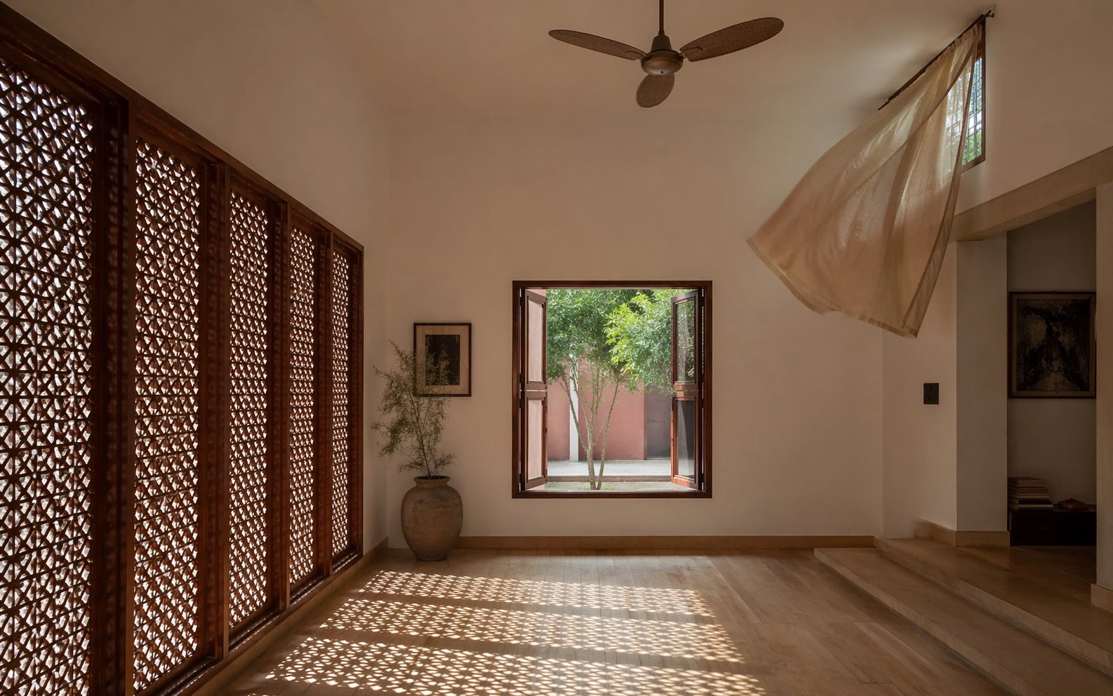
India's domestic architecture once breathed with extraordinary sophistication. The nalukettu of Kerala, the pol-house of Ahmedabad, the haveli of Rajasthan, the tenement-with-courtyard of Chettinad — each was a ventilation machine calibrated to its climate. Air moved through them continuously, driven by subtle pressure differences that their builders understood empirically and tuned through generations of iteration.
Modern Indian apartment design, by contrast, has largely forgotten how buildings breathe. Single-orientation glazing, deep floor plates without openings on opposite walls, fly-screens and security grilles stacked three-deep on every window, balconies enclosed with glass and turned into stores, internal bathrooms without ventilation shafts — these are the defining pathologies of twenty-first-century residential construction across Mumbai, Bengaluru, Delhi, Hyderabad, Chennai, and Pune. The cost is paid in dependence on air conditioning, in summer indoor temperatures that rise 4–6 °C above optimum, in chronic indoor air quality problems, and in an electricity bill that would be cut by 30–45 per cent if the walls simply worked (Manu et al., 2016; Indraganti, 2010).
This guide is an attempt to return cross-ventilation to the toolkit of the practising Indian architect. It covers the physics in rigorous but plain terms; the design geometry that governs how much air actually moves; the orientation, opening type, and room-depth rules that separate a well-ventilated home from a stagnant one; the four traditional Indian typologies that got this right and what they can teach modern practice; and the NBC 2016, IS 3362, and Eco-Niwas Samhita provisions that govern compliance. The companion Cross-Ventilation Analyzer tool implements the CIBSE AM10 simplified model discussed below; this guide is the theoretical foundation behind it.
"The open-to-sky space is, in a warm climate, the most important architectural element." — Charles Correa (1930–2015), from The New Landscape (Correa, 1985)
1. Why Cross-Ventilation Matters — Health, Energy, Comfort
Natural ventilation performs four functions simultaneously, each with measurable effect on occupant wellbeing and building performance.
Indoor air quality. A continuously ventilated room flushes CO₂, volatile organic compounds (VOCs), cooking fumes, and combustion products. CO₂ concentration is the most common proxy: outdoor air is approximately 420 ppm, acceptable indoor ceiling is 1,000 ppm (ASHRAE 62.1), and cognitive impairment becomes measurable above 1,400 ppm (Satish et al., 2012, Environmental Health Perspectives). A bedroom with four occupants and no ventilation reaches 2,000 ppm within 90 minutes of closing the door.
Thermal comfort. Air movement over skin increases convective and evaporative heat loss, lowering the perceived (effective) temperature. Empirical work by the India Model for Adaptive Comfort (IMAC) — the most extensive thermal comfort study conducted in India, covering 16 cities and 6,330 subjects — shows that an air velocity of 0.8 m/s extends the comfort band by approximately 2.5 °C compared with still air, and that Indian occupants of naturally ventilated buildings tolerate up to 32 °C indoor when air is moving (Manu et al., 2016). This single finding upends the assumption that indoor spaces must be cooled to 24 °C to be comfortable.
Energy. Space conditioning accounts for 30–45 per cent of residential electricity demand in Indian urban households (Krishnamurthy and Kriplani, 2013, cited in BEE, 2018). Homes designed for effective cross-ventilation reduce cooling hours by 40–70 per cent depending on climate zone (Dili, Naseer and Varghese, 2010; Chandel, Sharma and Marwah, 2016), a reduction that cumulatively matters at national scale.
Structural durability. Indoor humidity above 70 per cent for prolonged periods damages plaster, timber, upholstery, and electronics, and supports mould growth that becomes a chronic indoor air quality problem. Cross-ventilation flushes moisture as effectively as it flushes heat and CO₂.
Typical ACH Benchmarks for Indian Residential Spaces
| Room Type | Design Target (ACH) | Minimum Acceptable (ACH) | Source |
|---|---|---|---|
| Living / Dining | 6 | 3 | IS 3362 Clause 4; CIBSE TM40 |
| Bedroom (occupied) | 4 | 2 | ASHRAE 62.1 Table 6.2; IS 3362 |
| Kitchen (without hood) | 10 | 6 | SP 41 Section 3; NBC 2016 Part 9 |
| Bathroom / WC | 8 (exhaust) | 5 | NBC 2016 Part 8 Section 2 |
| Home office / study | 5 | 3 | ASHRAE 62.1 |
ACH (Air Changes per Hour) is the defining performance metric: it states how many times the air in the room volume is fully replaced per hour by outdoor air. A 48 m³ living room (4.5 × 3.5 × 3.0 m) at 6 ACH requires 288 m³/h of airflow.
"A house should open itself to the climate, not defend itself against it." — Laurie Baker (1917–2007), architect of Kerala
2. The Two Drivers — Wind and Buoyancy
Air moves through a building for one of two reasons, or both in combination.
Wind-driven flow arises when wind produces higher static pressure on the windward facade than on the leeward facade. The pressure difference drives air through the windward openings, across the interior, and out the leeward openings. This is the ventilation most architects think of first — and it is powerful when it works, but depends on the wind actually blowing and being approximately perpendicular to the windward facade.
Buoyancy-driven flow (also called stack or chimney effect) arises when indoor air is warmer than outdoor air. The warmer indoor air is less dense and rises; if an opening is available at the top of the warm column (clerestory, ventilator above a door, upper courtyard storey), the warm air leaves through it, and cooler outdoor air is drawn in through openings at the bottom. Stack flow is proportional to ΔT (indoor–outdoor temperature difference) and Δh (vertical distance between inlet and outlet), and it works at night, in still conditions, when wind-driven flow has shut off.
In real buildings the two effects act together. The standard approach (Etheridge, 2011; CIBSE, 2005) is envelope superposition — treat the two flows as independent and combine them as:
``
Q_total = √(Q_wind² + Q_stack²)
`
This is conservative: it assumes that when wind and stack drivers are aligned (both pushing air in the same direction) they add, and when opposed they cancel. In practice, well-designed buildings align the two — low windward inlets drive air in, and high leeward clerestories let warm stale air out, so both drivers reinforce the same flow path.

"If we do not look to the roots, we lose the knowledge of the centuries." — Hassan Fathy (1900–1989), Egyptian architect, from Architecture for the Poor (Fathy, 1973)
3. Wind-Driven Ventilation — The Physics
Pressure Coefficients
The wind arriving at a building creates a distribution of pressures on its surfaces. The windward face (the one the wind is blowing directly onto) experiences positive pressure; the leeward face experiences negative (suction); and the side facades show intermediate values depending on angle. The dimensionless surface pressure coefficient Cp relates local surface pressure to free-stream dynamic pressure:
`
Cp = (p_surface − p_free-stream) / (½ ρ V²)
`
For a rectangular building with the wind perpendicular to the windward facade, typical values from wind-tunnel measurements (Liddament, 1996; ASHRAE, 2021, Ch. 16) are:
| Facade | Cp (perpendicular wind) |
|---|---|
| Windward | +0.7 to +0.8 |
| Leeward | −0.2 to −0.4 |
| Sidewall | −0.5 to −0.7 |
| Flat roof | −0.3 to −0.6 |
The driving pressure difference ΔCp = Cp_inlet − Cp_outlet is what moves air. For a perpendicular wind with a windward inlet and leeward outlet, ΔCp ≈ 0.95. This is the design optimum.
Wind Approach Angle
Wind rarely blows perpendicular to any particular facade. As the wind angle rotates away from perpendicular, ΔCp falls — approximately as cos1.3(θ) for typical residential geometries (CIBSE AM10, 2005; Ghiaus and Allard, 2005):
| Approach Angle θ (degrees from normal) | ΔCp | Wind-flow effectiveness |
|---|---|---|
| 0 (perpendicular) | 0.95 | 100% |
| 15 | 0.88 | 93% |
| 30 | 0.78 | 82% |
| 45 | 0.60 | 63% |
| 60 | 0.37 | 39% |
| 75 | 0.15 | 16% |
| 90 (parallel to facade) | 0 | 0% |
The design implication is decisive: orienting openings to within ±30° of the prevailing wind is worth several times more airflow than any amount of opening enlargement. An apartment with 1.5 m² of window directly facing the wind ventilates better than one with 4.0 m² of window facing 75° off-axis.
Facade Wind Speed — Terrain Correction
Published wind speeds (from the India Meteorological Department, IMD) are measured at 10 m height over open terrain, typically at airfields. The actual wind speed at a residential facade depends on terrain roughness upstream, expressed by the power-law profile (IS 875 Part 3:2015):
`
V_z / V_ref = (z / z_ref)^α
`
where α is the terrain exponent:
| Terrain (IS 875 Category) | Description | α | Typical facade correction for 3rd-floor apt |
|---|---|---|---|
| Cat 1 | Open sea, flat open terrain | 0.14 | 0.95 × V_IMD |
| Cat 2 | Scattered obstructions, rural | 0.22 | 0.80 × V_IMD |
| Cat 3 | Suburban, periphery | 0.32 | 0.65 × V_IMD |
| Cat 4 | Dense urban, high-rise canyon | 0.43 | 0.45 × V_IMD |
A ground-floor flat in a dense Mumbai colony may receive only 35–45 per cent of the IMD-reported wind — a correction that a naive design omits entirely. The Cross-Ventilation Analyzer tool exposes this factor directly.
The Wind-Flow Equation
For a pair of openings, the wind-driven volumetric flow rate through the building is (CIBSE, 2005, Eq. 4.2):
`
Q_wind = Cd · A_eff · V_facade · √|ΔCp|
`
where Cd is the discharge coefficient of the controlling opening, A_eff is the paired-opening effective area (Section 5), V_facade is the facade wind speed (V_IMD × terrain factor), and ΔCp depends on orientation.
Prevailing Winds for Major Indian Cities
Long-term averages (IMD, 2020, Climatological Tables; supplemented by Manu et al., 2016) for the hot months when ventilation matters most:
| City | Mean wind (m/s at 10 m) | Prevailing direction (hot months) | Notes |
|---|---|---|---|
| Mumbai | 3.6 | W / SW (sea breeze) | Strong afternoon sea breeze — openings on W-facing facades capture this |
| Chennai | 3.4 | E / SE (sea breeze) | E-facing openings work well; N-S compromise for morning/afternoon |
| Kolkata | 2.7 | S (kal-baisakhi) | Southerly pre-monsoon; limited in dry season |
| Bengaluru | 2.8 | W / SW | Plateau-steady; modest but consistent |
| Pune | 3.0 | W | Western ghats funnel — strong afternoon breeze |
| Kochi | 2.9 | W (sea breeze) | Humid; supplement with stack |
| Hyderabad | 2.9 | W / SW | Deccan-plateau; mild |
| Delhi | 2.4 | NW (loo winds pre-monsoon) | Hot-dry; combine with thermal-mass night-flush |
| Ahmedabad | 2.6 | SW | Hot-dry; stack at night critical |
| Jaipur | 2.3 | W | Arid; wind-catcher orientation on W wall |
4. Buoyancy-Driven Ventilation — Stack and Night-Flush
When wind drops — a still night in Bengaluru in May, a humid afternoon in Chennai with the sea breeze slackening — wind-driven ventilation fails. Buoyancy takes over.
Warm indoor air is less dense than cool outdoor air. If the building provides a low inlet and a high outlet, the pressure difference driven by this density contrast pulls cool air in at the bottom and pushes warm air out at the top. The governing equation (Etheridge, 2011; Allard, 1998) is:
`
Q_stack = Cd · A_eff · √(2 g · Δh · ΔT / T_avg)
`
where g = 9.81 m/s², Δh is the vertical distance between inlet and outlet centres (m), ΔT is the indoor–outdoor temperature difference (K), and T_avg is the mean absolute temperature (K).
Stack Flow Sensitivity
| Δh (m) | ΔT = 2 K | ΔT = 5 K | ΔT = 8 K |
|---|---|---|---|
| 0.5 | 0.40 · Cd·A | 0.64 · Cd·A | 0.81 · Cd·A |
| 1.0 | 0.57 · Cd·A | 0.91 · Cd·A | 1.15 · Cd·A |
| 2.0 | 0.81 · Cd·A | 1.28 · Cd·A | 1.62 · Cd·A |
| 3.0 | 0.99 · Cd·A | 1.57 · Cd·A | 1.99 · Cd·A |
| 5.0 | 1.28 · Cd·A | 2.02 · Cd·A | 2.56 · Cd·A |
(Values in m/s flow velocity multiplied by Cd·A m². Assumes T_avg ≈ 300 K.)
Read this table carefully. A 0.5 m vertical offset at 2 K ΔT — the typical situation in a modern apartment with same-height opposite windows and a mild night — delivers roughly 40 per cent of what a 2 m offset at 5 K delivers. The classic courtyard house, with a full-storey stack (Δh ≈ 3–4 m) and strong diurnal temperature swing (ΔT ≈ 5–8 K in hot-dry climates), operates in the upper-right corner of this table. The modern apartment operates in the lower-left.
Night-Flush Cooling — The Hot-Dry Strategy
Hot-dry climates (Delhi, Jaipur, Ahmedabad, Jodhpur) present a thermal gift: the diurnal temperature swing is large (15–20 °C between day and night). A building with high thermal mass can be sealed during the day (preventing hot air entry), allowing the mass to absorb internal heat gains while remaining cooler than the exterior. At night, when the exterior drops below the interior, the building is opened and stack-ventilation flushes the stored heat out through high openings, drawing in cool night air through low openings. The cooled mass then serves as a "cold battery" through the following morning (Givoni, 1969; Santamouris, 2006).
The strategy works only if four conditions are met:
1. Diurnal swing ≥ 10 K (most Indian hot-dry cities in summer)
2. High thermal mass walls (230 mm brick minimum; 450 mm stone preferred)
3. Effective stack geometry — Δh ≥ 2 m with secure operable night openings
4. Building is actually closed during daytime (behavioural; automatable with motorised louvers)
Courtyard as Thermal Chimney
The traditional Indian courtyard is more than a decorative feature — it is a thermal chimney. Solar gain on the courtyard floor and walls creates rising warm air throughout the day, which pulls cooler air from shaded rooms at the perimeter, across the rooms, and up through the courtyard to the sky. At night, the same geometry operates in reverse: the courtyard radiates heat to the cold sky, cooling down faster than the enclosed rooms; the cool courtyard air sinks, flushing residual heat from the rooms through perimeter openings. Dili, Naseer and Varghese (2010) measured interior temperatures in traditional Kerala nalukettu houses 4–6 °C below ambient peak — with zero mechanical cooling.

"The verandah, the courtyard, the open corridor — these are the rooms of the tropical house." — Geoffrey Bawa (1919–2003), Sri Lankan architect
5. Effective Opening Area — Why Geometry Matters
A common mistake in residential design is to size openings by total area without understanding that airflow is controlled by the paired opening geometry. When air must pass through two openings in series (inlet and outlet), the effective flow area A_eff is:
`
A_eff = (A_in · A_out) / √(A_in² + A_out²)
`
This expression has three important properties:
Property 1 — Smaller opening dominates. If A_in = 1 m² and A_out = 4 m², A_eff = 4/√17 ≈ 0.97 m² — barely larger than the smaller opening alone. The flow is throttled at the smaller aperture. Quadrupling one opening while leaving the other fixed yields almost nothing.
Property 2 — Balanced pair gives A/√2. If A_in = A_out = A, A_eff = A/√2 ≈ 0.707A. Two equal 1 m² openings give 0.707 m² of effective area — not 2 m² as some architects assume, and not 1 m² either.
Property 3 — Single-sided is fundamentally different. With only one opening, the formula is inapplicable. The wind-driven flow through a single opening is due to turbulent pressure fluctuations at the opening edge, and is approximately two orders of magnitude smaller per unit area than a paired system (ASHRAE, 2021):
`
Q_single ≈ 0.005 · A · V_wind (empirical)
``
compared with Q_paired ≈ 0.05 · A_eff · V_wind (typical Cd × √ΔCp). Put concretely, a single-sided room achieves roughly 5 per cent of the ventilation of an equivalent cross-ventilated room. This is why deep, single-orientation apartments are ventilation disasters regardless of how large their windows are.

The Design Rule
| Condition | Design guidance |
|---|---|
| Cross-ventilation (openings on opposite walls) | Size both openings equal; aim for total operable area ≥ 15 % of floor area |
| Corner ventilation (openings on adjacent walls) | Accept ~45 % reduction vs cross; compensate with 20–30 % larger total area |
| Single-sided | Treat as ventilation failure at design stage; seek second opening |
| Stack-only (no wind expected) | Size for Δh ≥ 2 m; expect 30–50 % of wind-driven flow |
6. Opening Types and Discharge Coefficients
The dimensionless discharge coefficient Cd captures how efficiently a given opening converts pressure difference into volumetric flow. It depends on the opening's geometry — smooth apertures give high Cd, obstructed ones lower:

Cd Values and Effective Open-Area Ratios
| Opening Type | Cd | Open-Area Ratio (free flow fraction) | Source |
|---|---|---|---|
| Plain door (no obstruction) | 0.70 | 1.0 | CIBSE AM10 Table A2 |
| Plain casement/sliding window | 0.62 | 1.0 | CIBSE AM10; ASHRAE Handbook |
| Clerestory / ventilator (short-throat) | 0.55 | 1.0 | CIBSE AM10 |
| Window with mosquito screen | 0.50 | 1.0 | CIBSE AM10 (screen factor) |
| Louvered shutter (45° vanes) | 0.40 | 0.75 | IS 3362 Annex A |
| Window with security grille (<50% open) | 0.35 | 1.0 | Field-derived; Liddament (1996) |
| Jali — open pattern (55% porosity) | 0.34 | 0.55 | Krishan et al. (2001) |
| Jali — dense pattern (35% porosity) | 0.30 | 0.35 | Krishan et al. (2001) |
Effective flow area = geometric area × open-area ratio. A 1 m² dense jali has an effective flow area of only 0.35 m² before Cd is applied — its effective opening contribution is therefore 0.35 × 0.30 = 0.105 in pressure-area terms, roughly one-sixth of a plain 1 m² window at Cd 0.62.
Controlling Cd — in a cross-ventilated pair, the lower of the two openings' Cd values governs the flow (the flow is only as fast as the throttling element allows). A room with a plain casement inlet (Cd 0.62) and a dense-jali outlet (Cd 0.30) flows at Cd 0.30 overall.
Screens and Grilles — The Hidden Losses
Fly-screens cost approximately 15–20 per cent of the flow (CIBSE AM10; field measurements in Indraganti, 2010). Security grilles with less than 50 per cent open area can halve the flow. Stacking fly-screen plus grille plus heavy curtain produces composite losses of 60–70 per cent. Architects specifying 100 per cent of NBC-required opening area and then hanging all three layers over it are designing for failure.
Design guidance: specify the opening Cd explicitly in performance specifications. For bedrooms in malaria-belt cities (Assam, Odisha, coastal Andhra) where mosquito screens are non-negotiable, compensate by increasing geometric opening area by 20–25 per cent.
"Touch the earth lightly." — Glenn Murcutt (b. 1936), Australian architect, Pritzker Prize 2002

7. Orientation — Reading the Wind Rose
Orientation is the single most consequential decision for cross-ventilation performance. It is fixed at the plot-purchase or master-planning stage and cannot be remedied later by any amount of window enlargement.
The design input is the wind rose — a polar frequency diagram of wind direction and speed at the site, aggregated over the months when ventilation matters (typically March–October for most of India). IMD publishes wind roses for major cities in its Climatological Tables series; more recent data is available from CPCB monitoring stations and the ISHRAE weather file set (ISHRAE, 2014).
Orientation Principles by Climate Zone
Warm-humid (Mumbai, Chennai, Kochi, Kolkata): Maximise openings on the facade facing the prevailing sea breeze (W in Mumbai/Kochi; E in Chennai; S in Kolkata). Cross-openings on the opposite facade. The sea breeze is dependable: 2–4 m/s from mid-morning to late evening, failing only on rare overcast days.
Hot-dry (Delhi, Jaipur, Ahmedabad, Jodhpur): The daytime wind is hot and dust-laden — openings may actually worsen indoor comfort during peak hours (Givoni, 1969; Krishan et al., 2001). Strategy inverts: small daytime openings (operable for limited ventilation), large operable night openings oriented to the cooler night breeze (often a different direction from the daytime loo — typically NW or N).
Composite (Bengaluru, Pune, Hyderabad, Nagpur): Year-round cross-ventilation; prioritise prevailing wind (typically W or SW) with continuous operation in mild months and selective night-flush in summer.
Moderate (Bengaluru plateau, Ooty, Panchgani): Controlled ventilation. Mild all year; openings generous but with good rain protection.
Cold (Shimla, Srinagar, Shillong): Envelope-tight design for winter; openable only in summer for limited cross-flow.
Practical Orientation Rules
1. The longer facade of the building should align with ±30° of the prevailing warm-season wind.
2. Primary living spaces should face the prevailing wind directly (windward inlet).
3. Bedrooms benefit from night-wind orientation, which in many Indian cities differs from the daytime prevailing direction (IMD wind roses show this bimodal behaviour clearly).
4. Kitchen and utility areas should be on the leeward or crosswind side so cooking fumes and utility moisture are pulled out rather than blown through living spaces.
5. Puja rooms, studies, and guest bedrooms — intermittent occupation — can occupy less-ventilated positions.
6. Avoid orienting a primary facade parallel to the prevailing wind (θ = 90° gives ΔCp ≈ 0, and wind-driven flow vanishes).

8. Room Depth, Ceiling Height, and Flow Path

Ventilation performance degrades with room depth. Air entering through a window decelerates by viscous friction and jet spread; by a certain distance from the inlet, there is insufficient momentum to maintain flow, and a stagnant zone forms.
Depth-to-Height Rules
| Ventilation Type | Maximum effective depth (multiple of ceiling height H) |
|---|---|
| Single-sided, single opening | 2.0 × H |
| Single-sided, two openings at different heights | 2.5 × H |
| Cross-ventilation (opposite walls) | 5.0 × H |
| Cross-ventilation with courtyard stack | 7.0 × H |
These rules (Allard, 1998; Etheridge, 2011; IS 3362:1977) assume a ceiling height of 2.7–3.0 m. A 3.0 m ceiling room can support cross-ventilated room depth of 15 m — a generous 5-bay space. A 2.4 m ceiling (the depressing minimum common in modern Indian apartments) reduces the cross-ventilated depth to 12 m, and single-sided to 4.8 m — tight even for a bedroom.
Design implication: high ceilings are a passive-ventilation tool, not a decorative luxury. Traditional Indian homes typically used 3.0–4.0 m ceilings for exactly this reason. Modern apartment regulations and FSI pressures that push ceilings below 2.7 m impose a real ventilation penalty.
Ceiling Fans as Flow Extenders
Ceiling fans do not ventilate — they recirculate existing room air. But they meaningfully extend the thermal-comfort benefit of a given ACH by driving air velocity over the skin. A ceiling fan at medium speed produces air velocity of 0.8–1.2 m/s at occupant level, which per IMAC (Manu et al., 2016) extends the comfort band by 2.5–3.5 K. A well-ventilated room with a ceiling fan is comfortable at 30–32 °C indoor — a standard that naturally-ventilated buildings routinely meet across India's long summer.
9. Traditional Indian Typologies — What Still Works

Four centuries of iterative Indian building practice produced typologies that handled cross-ventilation with subtlety. Each is worth understanding because modern practice has largely forgotten their logic.
Comparison of Traditional Ventilation Typologies
| Typology | Region | Key ventilation feature | Achieves |
|---|---|---|---|
| Nalukettu | Kerala | Central nadumuttam (courtyard) + low deep eaves + timber jali | Continuous stack + perimeter cross-flow; 4–6 °C below ambient peak |
| Pol-house | Ahmedabad, Gujarat | Narrow plan, tall stack, central chowk; high windows on inner facade | Daytime shaded stack; night-flush via chowk to sky |
| Rajasthani haveli | Jaipur, Jodhpur, Bikaner | Jharokha (projecting balcony), high jaali screens, inner courtyard, thick stone | Wind acceleration through jaalis; thermal-mass night-flush |
| Tamil agraharam / row-house | Tamil Nadu | Thinnai (raised platform) + long deep plan + rear courtyard (koodam) | Shaded sea breeze funnelled; stack at rear |
| Bengali verandah-house | Kolkata, Murshidabad | Wrap-around verandah 3–5 m deep; high ceilings 4+ m; louvered shutters | Shaded perimeter ventilation; deep room penetration via verandah-door chain |
All five share four principles:
1. Openings on opposite sides at different heights — guaranteeing both wind-flow and stack-flow even when one driver fails.
2. A central open-to-sky space — courtyard or verandah acting as thermal chimney and circulation hub.
3. Shading integrated with ventilation — jalis, chajjas, verandahs that admit air while excluding direct sun.
4. High ceilings — 3.0–4.5 m common, multiplying the depth a room could be ventilated.
Modern practice inverted all four: small openings on one side, no open-to-sky intermediate, solid glazing without shading, and 2.4 m ceilings. The result is the apartment that requires 14-hour-a-day air conditioning to remain habitable.
Courtyard Physics
The quantitative contribution of a courtyard is striking. For a 4 × 4 m courtyard in a two-storey home with 6 m clear height:
- Stack Δh (courtyard floor to top-of-envelope): 6 m
- Daytime ΔT (sunlit courtyard stone vs shaded interior): 3–5 K in Ahmedabad summer
- Area of perimeter openings (summed across rooms opening onto courtyard): 8–12 m²
Applying the stack equation: Q_stack ≈ Cd × A_eff × √(2 × 9.81 × 6 × 4 / 300) ≈ 0.62 × A_eff × 1.25 ≈ 0.78 · A_eff m/s × 4 m² ≈ 3.1 m³/s, or about 11,000 m³/h. For a 150 m² house at 3 m ceiling (450 m³), this is 24 ACH — deep into "good" territory with no wind at all.
"A house is a machine for living in, but the climate is a parameter, not an enemy." — B.V. Doshi (1927–2023), Pritzker Prize laureate, paraphrased from his 1989 Aga Khan Award lecture
10. Climate-Zone Strategy Matrix
Cross-ventilation strategy must be specific to climate. ECBC 2017 and NBC 2016 Part 11 adopt a five-zone classification; residential design practice refines this into operational rules:
| Climate Zone | Cities | Dominant strategy | Ventilation posture |
|---|---|---|---|
| Hot-Dry | Jodhpur, Jaipur, Ahmedabad, Delhi, Aurangabad, Nagpur | Night-flush stack + daytime thermal mass | Limited small daytime openings; large operable night openings with secure louvers |
| Warm-Humid | Mumbai, Chennai, Kolkata, Kochi, Goa, Bhubaneswar, Visakhapatnam | Continuous cross-ventilation; avoid thermal mass | Maximum operable area year-round; prioritise opposite-wall cross-flow; stack weak due to low ΔT |
| Composite | Bengaluru, Pune, Hyderabad, Bhopal, Lucknow | Hybrid — cross-vent most of year; night-flush in summer dry season | Generous operable area with seasonal adjustability |
| Moderate | Bengaluru plateau, Ooty, Kodaikanal, Pune hill stations | Controlled ventilation; mild all year | Large openings with good weather sealing |
| Cold | Shimla, Srinagar, Shillong, Dharamsala, Leh | Envelope-tight for winter; summer-only cross-flow | Operable openings limited to summer; insulated frames; air-tight winter seal |
The single largest conceptual error in contemporary Indian practice is the application of warm-humid strategy to hot-dry cities — specifying large glazing on all facades of a Delhi or Jaipur apartment. The summer mid-afternoon loo at 45 °C blows dust and heat through those generous openings and, rather than cooling the interior, raises it 3–5 °C above what a sealed, mass-heavy building would achieve (Krishan et al., 2001; Chandel, Sharma and Marwah, 2016).
11. NBC 2016, IS 3362, and Eco-Niwas Samhita — Code Compliance
NBC 2016 Part 8 Section 1 — Ventilation
| Room Type | Minimum openable area (% of floor area) | Minimum openable fraction (of opening) |
|---|---|---|
| Habitable rooms (living, bedroom, kitchen) | 10 % | 50 % |
| Bathroom, WC | 5 % | 50 % or mechanical exhaust |
| Staircase, corridor | 7.5 % | 50 % |
| Kitchen (in addition to WFR) | Effective chimney/hood per IS 1884 | — |
A 15 m² living room requires 1.5 m² of openable window with at least 0.75 m² actually operable. The NBC requirement is prescriptive and binary — it does not guarantee good ventilation, only a minimum opening size. A room can pass NBC and still deliver 2 ACH if the opening geometry, orientation, or room depth is poor.
IS 3362:1977 — Natural Ventilation Recommendations
IS 3362 is the Indian performance standard for natural ventilation of residential buildings. Key provisions:
- Clause 4: Minimum 30 m³/h per person continuous air change in habitable rooms; 85 m³/h in tropical-humid zones; 200 m³/h in kitchen during cooking.
- Clause 5: Inlet and outlet must be provided on different facades, with inlet below body level and outlet above head level where feasible.
- Annex A: Tabulates discharge coefficients for common opening types (the basis for the Cd table above).
- Clause 6.3: Recommends minimum ceiling height of 2.75 m for naturally-ventilated rooms; 3.0 m in warm-humid zones.
IS 3362 is performance-based (specifies airflow) rather than prescriptive (specifies opening area); it is the appropriate reference for design verification. The Cross-Ventilation Analyzer tool produces IS 3362-compliant reports directly.
Eco-Niwas Samhita 2018 — Residential ECBC
| Provision | Requirement |
|---|---|
| Openable Window Area (OWA) | ≥ 10 % of carpet area for habitable rooms |
| Ventilation Rate Requirement | Per IS 3362 / ASHRAE 62.1, whichever applies |
| Window-to-Wall Ratio (WWR) | Upper limit varies by climate; warm-humid permits higher |
| Shading Requirement | Solar heat-gain coefficient (SHGC) limits by orientation |
Eco-Niwas Samhita 2018 applies to residential buildings with plot area ≥ 500 m² and is progressively becoming mandatory for state housing schemes. Its provisions complement NBC 2016 Part 8 rather than replace them.
NBC 2016 Part 11 — Climate Classification
NBC 2016 Part 11 establishes the five climate zones used throughout Indian building regulation and forms the basis for zone-specific ventilation, shading, and glazing provisions. It classifies cities using annual mean temperature and annual relative humidity thresholds. Designers should always confirm climate zone assignment from NBC 2016 Part 11 rather than informal attributions — several cities sit at zone boundaries.
12. Common Apartment Failures — and Retrofits
Even within the constraints of existing apartment typologies, cross-ventilation can often be substantially improved. Common failures and their remedies:
| Failure Mode | Typical symptom | Retrofit |
|---|---|---|
| Single-orientation glazing | Entire living-dining on one facade | Open interior doors during day; deploy cross-flow via window + main entrance door + service window |
| Balcony enclosed with glass | Designed cross-flow opening blocked | Convert enclosure to operable louvered/sliding system with ≥ 50 % openable area |
| Security grilles over windows | 50–60 % flow loss | Specify grilles with ≥ 70 % open area; expanded mesh or vertical-slat designs over plate grille |
| Triple-layer fly-screen + grille + curtain | 70 % cumulative flow loss | Choose one insect barrier per room; manage curtains based on time of day |
| No clerestory / high outlet | Stack flow unavailable | Add transom operable above doors; openable clerestory in service/utility areas |
| Internal bathroom, no shaft | Humidity and odour accumulation | Retrofit mechanical exhaust with humidistat control; min 25 L/s |
| Kitchen without range hood | Cooking fumes cross rooms | Install IS 1884-compliant hood, exhaust to exterior, not recirculating |
| Deep plan with no central open-to-sky | Middle rooms stagnant | Create light/ventilation shaft if structure permits; otherwise mechanical supply through duct |
Most of these interventions are achievable in an existing apartment by the owner within a moderate budget. The larger point — for architects designing new buildings — is that the failure modes are all preventable at zero cost at the planning stage.
The Architect's Checklist
Before committing a plan, verify:
1. Each habitable room has openings on at least two different facades (or one facade + a courtyard/light-shaft).
2. Prevailing warm-season wind is aligned within ±30° of the primary inlet facade.
3. Cross-ventilated room depth ≤ 5 × ceiling height.
4. NBC 2016 Part 8 Section 1 WFR minima met for each room.
5. Opening Cd after grilles and screens is ≥ 0.35 for primary inlets.
6. Kitchen has both plan ventilation (cross-flow) and active ventilation (hood per IS 1884).
7. Bathrooms have operable window OR mechanical exhaust per NBC 2016 Part 8.
8. At least one stack route exists — door-transom pairs, clerestory-over-courtyard, or light-shaft — to cover still-air conditions.
9. Ceiling fans integrated into living and sleeping spaces for comfort-band extension.
10. IS 3362 air-change targets met for design-day conditions (verified in the Cross-Ventilation Analyzer).
"Every building is a climate instrument, whether its architect intended it or not." — Anupama Kundoo (b. 1967), architect, paraphrased from Kundoo (2020)
References
- Allard, F. (1998) Natural Ventilation in Buildings: A Design Handbook. London: James & James Science Publishers.
- ASHRAE (2019) ANSI/ASHRAE Standard 62.1-2019: Ventilation for Acceptable Indoor Air Quality. Atlanta: American Society of Heating, Refrigerating and Air-Conditioning Engineers.
- ASHRAE (2021) Handbook — Fundamentals. Chapter 16: Ventilation and Infiltration. Atlanta: ASHRAE.
- Bansal, N.K. and Minke, G. (1988) Climatic Zones and Rural Housing in India. Jülich: Kernforschungsanlage Jülich GmbH.
- Bureau of Indian Standards (1977) IS 3362:1977 — Code of Practice for Natural Ventilation of Residential Buildings. New Delhi: BIS.
- Bureau of Indian Standards (1984) IS 1884:1984 — Specification for Kitchen Hood and Chimney. New Delhi: BIS.
- Bureau of Indian Standards (1987) SP 41 (S&T):1987 — Handbook on Functional Requirements of Buildings (other than Industrial Buildings). New Delhi: BIS.
- Bureau of Indian Standards (2015) IS 875 (Part 3):2015 — Code of Practice for Design Loads (Other than Earthquake) for Buildings and Structures — Wind Loads. New Delhi: BIS.
- Bureau of Indian Standards (2016) SP 7:2016 — National Building Code of India 2016. New Delhi: BIS.
- Bureau of Energy Efficiency (2018) Eco-Niwas Samhita 2018: Energy Conservation Building Code for Residential Buildings. New Delhi: BEE, Ministry of Power, Government of India.
- Chandel, S.S., Sharma, V. and Marwah, B.M. (2016) 'Review of energy-efficient features in vernacular architecture for improving indoor thermal comfort conditions', Renewable and Sustainable Energy Reviews, 65, pp. 459–477.
- CIBSE (2005) AM10: Natural Ventilation in Non-Domestic Buildings. London: Chartered Institution of Building Services Engineers.
- CIBSE (2015) Guide B2: Ventilation and Ductwork. London: CIBSE.
- Correa, C. (1985) The New Landscape: Urbanisation in the Third World. Mumbai: Book Society of India.
- Dili, A.S., Naseer, M.A. and Varghese, T.Z. (2010) 'Passive environment control system of Kerala vernacular residential architecture for a comfortable indoor environment: a qualitative and quantitative analyses', Energy and Buildings, 42(6), pp. 917–927.
- Etheridge, D. (2011) Natural Ventilation of Buildings: Theory, Measurement and Design. Chichester: Wiley.
- Fathy, H. (1973) Architecture for the Poor: An Experiment in Rural Egypt. Chicago: University of Chicago Press.
- Ghiaus, C. and Allard, F. (Eds.) (2005) Natural Ventilation in the Urban Environment: Assessment and Design. London: Earthscan.
- Givoni, B. (1969) Man, Climate and Architecture. London: Applied Science Publishers.
- India Meteorological Department (2020) Climatological Tables of Observatories in India 1981–2010. New Delhi: IMD.
- Indraganti, M. (2010) 'Thermal comfort in naturally ventilated apartments in summer: findings from a field study in Hyderabad, India', Applied Energy, 87(3), pp. 866–883.
- ISHRAE (2014) ISHRAE Weather Data File Set for Indian Cities. New Delhi: Indian Society of Heating, Refrigerating and Air Conditioning Engineers.
- Koenigsberger, O.H., Ingersoll, T.G., Mayhew, A. and Szokolay, S.V. (1973) Manual of Tropical Housing and Building: Part 1 — Climatic Design. London: Longman.
- Krishan, A., Baker, N., Yannas, S. and Szokolay, S. (Eds.) (2001) Climate Responsive Architecture: A Design Handbook for Energy Efficient Buildings. New Delhi: Tata McGraw-Hill.
- Kundoo, A. (2020) Taking Time. Barcelona: Urbanext.
- Liddament, M. (1996) A Guide to Energy Efficient Ventilation. Coventry: Air Infiltration and Ventilation Centre (AIVC).
- Manu, S., Shukla, Y., Rawal, R., Thomas, L.E. and de Dear, R. (2016) 'Field studies of thermal comfort across multiple climate zones for the subcontinent: India Model for Adaptive Comfort (IMAC)', Building and Environment, 98, pp. 55–70.
- Oke, T.R. (1987) Boundary Layer Climates. 2nd edn. London: Routledge.
- Rapoport, A. (1969) House Form and Culture. Englewood Cliffs: Prentice-Hall.
- Santamouris, M. (Ed.) (2006) Advances in Passive Cooling. London: Earthscan.
- Satish, U., Mendell, M.J., Shekhar, K., Hotchi, T., Sullivan, D., Streufert, S. and Fisk, W.J. (2012) 'Is CO₂ an indoor pollutant? Direct effects of low-to-moderate CO₂ concentrations on human decision-making performance', Environmental Health Perspectives, 120(12), pp. 1671–1677.
- Szokolay, S.V. (2014) Introduction to Architectural Science: The Basis of Sustainable Design. 3rd edn. London: Routledge.
Author's Note: The simplified ventilation model presented here (CIBSE AM10 envelope superposition with IS 3362 Cd values) is appropriate for schematic and design-development decisions. For LEED v4.1, GRIHA 2019, or code-path performance credits, designers should validate with EnergyPlus AirflowNetwork (AFN) or IES-VE MacroFlo using a full pressure-node network and an ISHRAE weather file. The Cross-Ventilation Analyzer tool at /for-designers/cross-ventilation-analyzer implements the AM10 simplified model and is sufficient for preliminary and design-development stage work; the present guide provides the theoretical and regulatory basis behind it.
Disclaimer: This article is for informational and educational purposes only. It does not constitute professional architectural or engineering advice. Cross-ventilation design must be undertaken by qualified professionals in accordance with the Indian Standards, National Building Code, and local bye-laws cited. Studio Matrx, its authors, and its contributors accept no liability for decisions made on the basis of the information contained in this guide.
Interactive · Cross-ventilation patterns
Opposite walls · Excellent · 4-8 ACH
Inlet and outlet on facing walls — straight-line cross-breeze through the room.
Pros
- • Strongest cross-ventilation
- • Whole room flushed
- • Comfortable without fan most of the year
Cons
- • Privacy needs window treatments
Export this guide
Related Guides — Deep-dive reading
Climate-Responsive Facades for India: Designing Your Home's Skin for Your Weather
A homeowner's plain-language guide to the facade strategy for every Indian climate zone — what your walls, windows, shading, and colours should actually do where you live
Building FacadesEnergy-Efficient Facades in India: How the Building Skin Cuts Your Cooling, Heating & Lighting Bills
How a building facade drives cooling, heating and lighting energy in India, the three levers of solar-heat-gain control, insulation and daylighting, U-value, SHGC, VLT and WWR in plain terms, ECBC and Eco-Niwas expectations, and real Indian green buildings.
Building FacadesDesigning a Naturally Energy-Efficient Indian Home
Comfort first, gadgets last — passive design, orientation, insulation, ventilation and the climate wisdom that cuts Indian energy bills
SustainabilityRelated Tools — Try Free
Brise-Soleil Visualizer
Interactive horizontal-louvre cut-off angle calculator — sun altitude, louvre depth, and spacing inputs with a live shadow preview. Computes θ = arctan(spacing/depth) for façade shading, ECBC envelope compliance, hospital daylight design, and tropical sun-control detailing.
Sun Shading ToolCross-Ventilation Analyzer
Estimate airflow and air changes per hour (ACH) from room size, window areas, layout, and local wind — with NBC 2016 Part 8 compliance check.
Ventilation CalculatorGreen Building Window Compliance Tool
Check your window design against Eco-Niwas Samhita — WWR, VLT, SHGC and U-value pass or fail.
ENS Pre-check