
Camera Field-of-View Schedule for India (2026): Proving Each Camera Sees What It Should
A ready-to-adapt professional schedule that records, per camera, the scene it must cover and to what purpose level - monitor, detect, recognise or identify - so coverage intent is stated at design and proven at commissioning.
A camera list tells you where cameras are. A camera field-of-view schedule tells you what each one is actually meant to see - and to what quality. It is the document that pins down coverage intent: for every camera, the scene it must cover, how much of the frame the target should fill, and therefore whether the design will hold up when something happens. Without it, "we have thirty cameras" is a count, not a coverage guarantee.
This is a companion to the plain camera list in the camera schedule and the area-by-area picture in the CCTV coverage schedule. Where those record hardware and zones, the field-of-view schedule records purpose and proof - and it is written at design, then verified line by line at commissioning. It sits inside the wider professional security resources toolkit.
Scope and how to read this. This is a ready-to-adapt professional template, not authoritative, contractual or legal wording. The exact lens, sensor, mounting height and pixel density for any purpose level come from your project, the site survey, the equipment you specify and the manufacturer data - engineer each camera to its purpose. Get professional review for the contract documents. Where a real figure belongs, this page says "specify" or "engineer to purpose" rather than inventing a number.
What the schedule is, and where it sits
The field-of-view schedule is produced by the security consultant, designer or PMC during design, alongside the camera layout. It is issued for procurement so the installer prices the right lenses and mounts, and it becomes the acceptance yardstick at commissioning: each camera is walked, its live view compared to the intent, and only then is the row marked verified. It is handed over as part of the as-built pack.
Think of it as the bridge between a marketing promise ("full coverage") and an engineering fact ("this camera, at this scene, achieves this purpose"). It makes coverage auditable.
The concept: purpose drives the view
Every camera in the schedule is defined by five linked decisions. Get the first right and the rest follow.
- Scene / target. What must this camera cover - a gate line, a lobby, a cash counter, a car park aisle? Name it plainly.
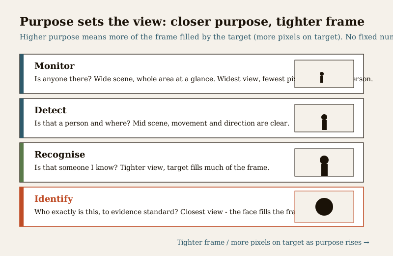
- Purpose level. What must the footage let you do? The widely used ladder runs monitor, detect, recognise, identify. Monitor: is anyone in the area at all. Detect: a person is present and where they are moving. Recognise: this is someone I already know. Identify: establish who a stranger is to an evidential standard. The key idea, in words: the higher the purpose, the more of the frame the target must fill - more pixels on target - which means a tighter, closer view.
- Intended view. Wide, mid or tight, following directly from the purpose. Identify needs the closest, tightest view of the lot; monitor tolerates the widest.
- Coverage width and distance intent. How wide a scene at roughly what range - a doorway a few metres away, or an approach path further out. State the intent; the exact distance for a purpose is engineered, not guessed.
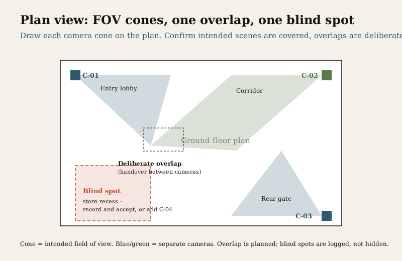
- Lens / angle and blind spots. The angle of view needed to hold the scene, plus any overlap with a neighbour (deliberate, for handover between cameras) and any blind spot (recorded and accepted, or closed with another camera).
Do not chase one camera doing everything. A single wide camera cannot both survey a whole yard and identify a face at the gate - those are different purpose levels needing different views. Split the job: a wide "detect" camera for the scene, a tight "identify" camera on the choke point. The schedule makes that split explicit.
Worked example: a filled field-of-view schedule
Example only - adapt to your project. Values are generic and illustrative. Lenses, angles, distances and pixel densities are shown as "specify" or "engineer to purpose" - never copy them as facts.
| Camera ref | Scene / target | Purpose level | Intended view | Approx distance intent | Lens / angle note | Lighting / IR need | Blind-spot / overlap note | Verified at commissioning |
|---|---|---|---|---|---|---|---|---|
| C-01 | Main gate approach - people entering | Identify | Tight | Choke point, close range - specify | Narrow angle to fill frame with face; engineer to purpose | Even face lighting; avoid backlight - see lighting guide | Overlaps C-02 for handover | Y / N |
| C-02 | Front boundary line | Detect | Wide | Along the line - specify | Wide angle to hold the run; engineer to purpose | IR or low-light rated for night | Overlaps C-01; blind spot behind planter recorded | Y / N |
| C-03 | Lobby and reception counter | Recognise | Mid | Room depth - specify | Angle to keep counter and door in frame | Interior lighting adequate; confirm on site | No overlap; corner near lift is blind - accepted | Y / N |
| C-04 | Basement parking aisle | Detect | Wide | Aisle length - specify | Wide angle down the aisle; engineer to purpose | IR required; confirm range for aisle | Overlaps C-05 at ramp | Y / N |
| C-05 | Ramp and shutter | Recognise | Mid | Ramp mouth - specify | Angle to read a person and vehicle direction | IR at night; headlight glare to be checked | Overlaps C-04 | Y / N |
| C-06 | Rear service gate | Identify | Tight | Close range at gate - specify | Narrow angle for face at the leaf | Dedicated light or IR; verify at night | Blind spot in bin bay recorded, accepted | Y / N |
Blank, copy-ready template
Copy this into your sheet or drawing register. One row per camera; carry the same camera refs used in your camera list and coverage schedule so the documents cross-check.
| Camera ref | Scene / target | Purpose level (monitor / detect / recognise / identify) | Intended view (wide / mid / tight) | Approx distance intent | Lens / angle note | Lighting / IR need | Blind-spot / overlap note | Verified at commissioning (Y / N) |
|---|---|---|---|---|---|---|---|---|
| ... | ... | ... | ... | ... | specify | ... | ... | Y / N |
| ... | ... | ... | ... | ... | specify | ... | ... | Y / N |
| ... | ... | ... | ... | ... | specify | ... | ... | Y / N |
| ... | ... | ... | ... | ... | specify | ... | ... | Y / N |
Field guide: how to fill each column well
- Camera ref. Reuse the reference from the camera schedule exactly. One camera, one ref, across every document.
- Scene / target. Name the thing that must be captured, not just the room. "People entering at the gate" is stronger than "gate area" because it forces a purpose decision.
- Purpose level. Pick the highest level the scene genuinely needs, and no higher - identify everywhere is expensive and rarely justified. Choke points where a face must be established get identify; open areas get detect. The coverage planning guide helps decide.
- Intended view. Wide, mid or tight, matched to the purpose. Remember the rule: identify needs the closest view. If the scene is wide and the purpose is identify, that is a signal you need two cameras, not one.
- Distance intent. State the range you are designing for. The exact pixel density that achieves a purpose at that range is engineered from the equipment - specify it with the manufacturer data, do not assume.
- Lens / angle note. Record the intent ("narrow angle to fill frame with a face"); the final focal length and sensor are selected during procurement to meet it.
- Lighting / IR need. A purpose is only met if the scene is lit. Identify at a gate at night needs face-quality light or IR; note the need here and design it with the lighting for facial identification guidance. Backlight from a bright sky or headlights defeats an identify camera even in daylight.
- Blind-spot / overlap note. Mark overlaps as deliberate handover zones, and record blind spots honestly. A logged, accepted blind spot is a design decision; an unnoticed one is a failure waiting to be found after an incident. Perimeter runs especially need this discipline - see perimeter CCTV.
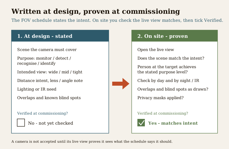
- Verified at commissioning. Left as N at design. It only becomes Y when someone stands on site, opens the live view and confirms the scene matches the stated purpose.
Verifying on site: turning intent into proof
Commissioning is where the schedule earns its keep. For each camera, open the live view and check:
- Does the scene match? The framed area is what the schedule says it should be, with the deliberate overlaps present.
- Is the purpose met? Have a person stand at the target and judge whether the footage supports the stated purpose - can you monitor, detect, recognise or identify as intended? Where identify is claimed, the face must be usable, not a distant blur.
- Day and night. Check again under night or IR conditions. A camera that identifies at noon and fails at midnight has not met an identify purpose.
- Blind spots as drawn. Confirm the accepted gaps are the ones on the plan and no new ones have appeared from a shifted mount.
Only then mark the row verified, date it and note who checked. A camera is not accepted until its live view proves it sees what the schedule promised.
Privacy and DPDP. Footage that identifies people is personal data under the Digital Personal Data Protection Act, 2023. A field-of-view schedule is also a privacy control: it defines exactly what each camera is meant to see, which means anything outside that intent - a neighbour window, a private balcony, a residential interior - should be masked or the camera re-aimed. Record required privacy masks against the relevant rows and confirm they are applied at commissioning. Do not over-capture beyond the stated purpose.
How it connects to the neighbouring documents
The field-of-view schedule does not stand alone:
- The camera schedule lists the hardware and refs; this schedule adds the purpose and view for each of those refs.
- The CCTV coverage schedule rolls the cameras up into area-by-area coverage; the field-of-view rows are the evidence beneath it.
- The coverage planning guide is where the purpose decisions are reasoned before they land in these rows.
- Commissioning uses the "Verified" column as its acceptance checklist, and the completed schedule is handed over as part of the as-built record.
Keep the camera refs identical across all of them, issue the field-of-view schedule with the layout at design, and close it out at commissioning. That is how coverage stops being a claim and becomes something you can prove.
Completion checklist
- Every camera ref from the camera schedule has a row here.
- Each row states a scene, a single purpose level, and an intended view that matches that purpose.
- Distance, lens/angle and lighting are recorded as intent ("specify" / "engineer to purpose"), not invented numbers.
- Overlaps are marked deliberate; blind spots are recorded and accepted or closed.
- Required privacy masks are noted against the relevant rows (DPDP).
- The "Verified at commissioning" column is filled on site, dated and signed off.
References
- Digital Personal Data Protection Act, 2023 - CCTV footage identifying people is personal data; capture only what the stated purpose needs, mask areas outside intent, and keep access and retention controlled.
- Manufacturer camera and lens data - the authoritative source for the angle of view, sensor and pixel density that achieve a given purpose at a given distance; engineer each camera to its purpose from this data.
- Recognised CCTV operational-requirement practice (monitor / detect / recognise / identify purpose levels) - use as a qualitative framework; confirm the specific pixel-on-target criteria with your equipment and project standard.
- Bureau of Indian Standards catalogue - verify the current edition of any standard referenced in your specification at https://www.services.bis.gov.in/
This is an educational, ready-to-adapt template, not authoritative, contractual or legal advice. Lens selection, mounting and any electrical work are qualified professional tasks - engage licensed professionals, and consult a professional for legal or data-protection questions.
Export this guide
Related Guides — Deep-dive reading
CCTV Coverage Schedule for India (2026): Mapping Every Camera to a Purpose
A ready-to-adapt design-stage schedule that lists every zone to be covered, ties each one to a camera reference and a coverage purpose, and makes gaps and overlaps visible before you write the camera schedule and BOQ.
SecurityLighting for Facial Identification in India (2026): How Light Turns CCTV Footage From a Hooded Shape Into a Face You Could Name
Detection, recognition, identification: how to light the gate, door or lift lobby so a camera captures a face that is actually identifiable as evidence, not just proof that someone was there.
SecurityProfessional Security Resources for India (2026): The Documents Behind a Secure Project
The overview and map of the whole professional-deliverable toolkit — the brief, schedules, BOQ, checklists, handover pack and logs a consultant, designer, PMC or facility manager produces across a security project, and how each document connects to the next.
SecurityRelated Tools — Try Free
CCTV Commissioning & Handover Checklist
An interactive go/no-go checklist to run at handover — cameras day and night, recording, alerts, passwords and documents — before you clear the final bill.
Handover ChecklistCCTV Camera Overlap Calculator
The overlap or blind gap between two adjacent cameras, from coverage width and spacing, plus the spacing for a target overlap.
OverlapSite & Perimeter Security Assessment
Rate your site across five areas — site, neighbourhood, perimeter, entry/exit and lighting — for a readiness score and prioritised fixes.
Site Assessment