
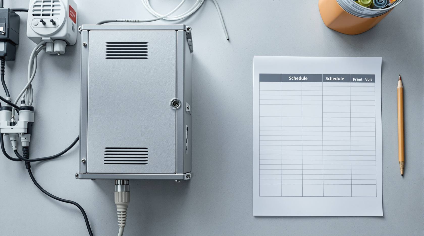
Security Power Schedule for India (2026): Every Device, Its Supply and Its Backup
A ready-to-adapt schedule that lists every security device, how it is powered and how it is backed up, so nothing goes dark unexpectedly during a power cut.
A security system is only as reliable as the power behind it. The cameras at the gate, the alarm panel, the access controllers and the recorder each draw power from somewhere, and each needs to be told what to do when the mains fails. The security power schedule is the one document that captures that: every device, how it is supplied, and how it is backed up. Get it right and the system keeps watching through a power cut. Skip it and you find out the hard way, at the worst possible time, that the recorder was never on the UPS.
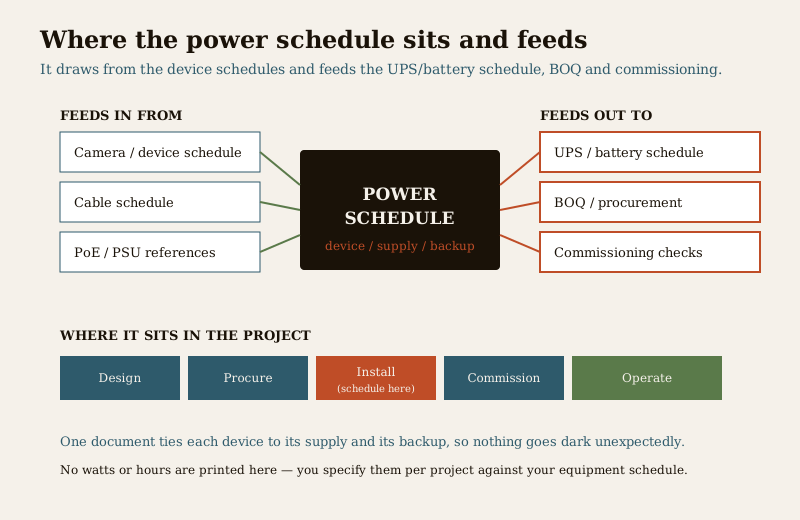
This resource sits in Studio Matrx's professional security resources library as a practitioner deliverable. It is produced during design and firmed up at install: it draws from the camera and device schedule and the cable schedule, it feeds the UPS and battery sizing, the BOQ, and the commissioning checks. Think of it as the bridge between "what equipment are we installing" and "what power and backup does it all need."
Scope & how to read this. This is a ready-to-adapt professional template, not authoritative or contractual wording. The actual watts, amps, VA and backup hours come from your project, your equipment data sheets and your electrical designer, and any mains-side work must be designed and carried out by a licensed electrician. Nothing here fixes a number for you. Get professional and legal review for contract documents (specification, BOQ, tender), and defer specifics to your equipment manufacturers and the authority having jurisdiction.
What the power schedule is and where it sits
A power schedule is a table with one row per device or device group and a column for each power question: what supplies it, from which source, how much it draws, whether it must be backed up, from what backup source, and for how long. It is not the electrical drawing and it is not the UPS calculation; it is the load list that both of those depend on.
In the project lifecycle it appears at design, is refined during procurement as real equipment is chosen, and is finalised at install and commissioning when the actual devices and supplies are on site. The security consultant or designer produces it; the electrical designer, installer and commissioning engineer receive it. It matters because it is the single place where "does the recorder stay on during a cut" is answered on purpose rather than by accident.
The concept in plain terms
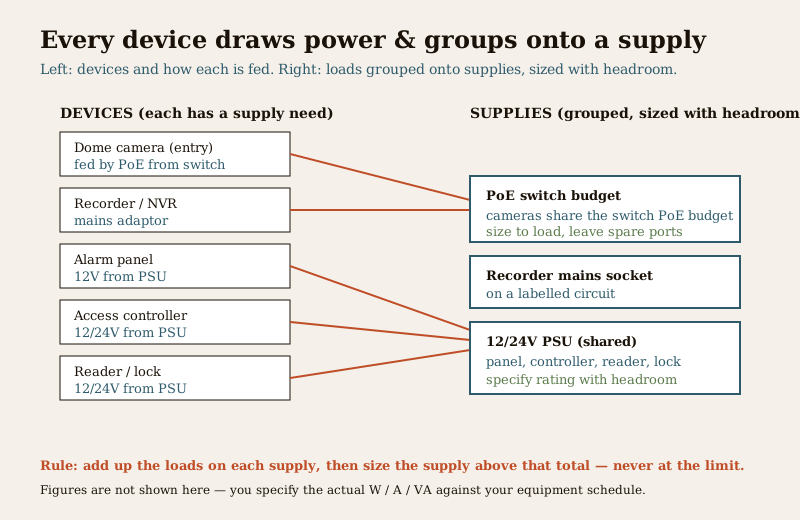
Every device is fed one of a few ways. A recorder or a standalone camera often runs off a mains adaptor. Network cameras are usually fed by PoE (Power over Ethernet) from the switch, so they share the switch power budget. Panels, controllers, readers and electric locks typically run on low-voltage 12V or 24V from a PSU (power supply unit). The schedule records which of these applies to each device.
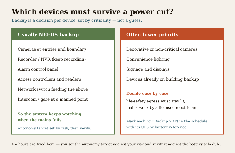
Then you group the loads. Cameras share a switch, so their loads add up against that switch PoE budget. Several low-voltage devices share a PSU, so their loads add up against that PSU rating. You size each supply above the total it carries so there is headroom for start-up surge and future additions, never right at the limit. And separately, for each device, you decide backup by criticality: the cameras at entries and the boundary, the recorder, the alarm panel, the access controllers and the switch that feeds them usually need to ride through a cut, so they sit on a UPS or battery with an autonomy target set by risk. A decorative camera or a convenience display may not. The schedule is where every one of those decisions is written down and checked.
Worked example power schedule
Here is a realistic, illustrative power schedule for a small mixed system. It shows how the columns are used together. The loads and autonomy targets are written as "specify" and "size to load" on purpose, because those numbers belong to your actual equipment and your risk assessment, not to a template.
Example only, adapt to your project. Device names, supply types and references below are generic illustrations. Do not copy the loads or hours as facts; each of them says "specify" because you fill it from the data sheet and the sizing calculation.
| Device / group | Supply type | Source (PSU / switch ref) | Load note | Backup Y/N | Backup source | Autonomy target | Status |
|---|---|---|---|---|---|---|---|
| Cameras C-01 to C-04 (entries) | PoE | SW-01 PoE budget | specify W per camera | Y | UPS-01 | set by risk, verify | Design |
| Recorder / NVR | Mains adaptor | Socket on labelled circuit | specify W | Y | UPS-01 | set by risk, verify | Design |
| PoE switch SW-01 | Mains adaptor | Socket on labelled circuit | size to load | Y | UPS-01 | set by risk, verify | Design |
| Alarm control panel | 12V DC | PSU-01 | specify A | Y | Panel standby battery | per panel spec, verify | Design |
| Access controller AC-01 | 12/24V DC | PSU-02 | specify A | Y | PSU-02 battery | set by risk, verify | Design |
| Reader / electric lock, Main Gate | 12/24V DC | PSU-02 | specify A (incl. lock) | Y | PSU-02 battery | set by risk, verify | Design |
| Camera C-05 (decorative, lobby) | PoE | SW-01 PoE budget | specify W | N | none | not required | Design |
Every "Y" in the Backup column is a promise you make to the UPS and battery schedule; every load note is a number the electrical designer needs. The Status column tracks each row from Design through Procure, Install and Commission.
Blank, copy-ready template
Copy this table into your project sheet and fill one row per device or group. Keep the "specify / size to load / verify" habit until real numbers are confirmed against data sheets and the sizing calculation.
| Device / group | Supply type | Source (PSU / switch ref) | Load note | Backup Y/N | Backup source | Autonomy target | Status |
|---|---|---|---|---|---|---|---|
| ... | mains / PoE / 12V / 24V | ... | specify W / A | Y / N | UPS / battery ref | set by risk, verify | Design |
| ... | ... | ... | ... | ... | ... | ... | ... |
| ... | ... | ... | ... | ... | ... | ... | ... |
Column and field guide
- Device / group. One device, or a sensible group that shares a supply (for example all cameras on one switch). Use the same IDs as your camera and device schedule so the documents line up.
- Supply type. How it is fed: mains, PoE, or low-voltage 12V or 24V DC. This decides which source column applies.
- Source (PSU / switch ref). The specific supply that feeds it, by reference, so the schedule ties to a real PSU or switch, not "a socket somewhere."
- Load note. The draw, written as "specify W" or "size to load" until confirmed from the data sheet. Do not guess a number, and do not carry a proposal figure as if it were measured.
- Backup Y/N. Whether this device must survive a cut. This is a criticality decision, covered next.
- Backup source. The UPS, panel standby battery or PSU battery that carries it, by reference, so the UPS and backup design can size it.
- Autonomy target. How long it must ride through, set by risk not by guess, then verified against the battery calculation.
- Status. Design, Procure, Install or Commission, so the schedule tracks reality as the job progresses.
Field guide: how to use it well
Group loads onto supplies, then size with headroom. Add up everything on a PoE switch against its budget, and everything on a PSU against its rating, then choose a supply comfortably above that total. Sizing a PSU right at its rated output leaves no room for surge or a future device and is a common cause of nuisance dropouts. The security power supply requirements explainer covers how PoE budgets and PSU headroom work, and links the electrical safety picture, because mains work is a licensed electrician's job.
Back up the critical devices, deliberately. The devices that make the system a security system, the entry and boundary cameras, the recorder, the alarm panel, the access controllers and the switch feeding them, usually need backup so the system does not go blind during a cut. Mark each one clearly and tie it to a backup source. Decide the rest case by case; a decorative camera may not warrant a battery, but life-safety egress lighting must stay lit regardless.
Set autonomy by risk, not by a round number. How many hours of backup you need depends on the site, the typical outage, and how critical continuous coverage is, not on a figure copied from another job. Write the target as "set by risk, verify" and confirm it against a proper battery sizing rather than a round number guessed on site.
Common mistakes to avoid.
- No backup on critical devices. The recorder or the switch left off the UPS, so a cut takes the whole system down and no footage is recorded during the very event you cared about.
- A PSU or switch sized with no headroom. Loaded to its limit, it browns out under surge or the moment one more device is added.
- Guessed loads carried as facts. A proposal wattage treated as measured, so the UPS is undersized and the autonomy never materialises.
- Sources left vague. "On the socket" instead of a referenced PSU or switch, so nobody can trace what feeds what during a fault.
How it connects to the neighbouring documents
The power schedule is a hub. It draws from the camera and device schedule, which lists what is being installed, and from the cable schedule, which shows how each device is wired and where the PoE and PSU runs go. It feeds the UPS and battery schedule, so the CCTV and security power backup design can size the autonomy for every device you marked "Y." It feeds the BOQ, because each supply and battery becomes a procurement line. And it feeds commissioning, where the installer confirms that every device is actually on the supply and backup the schedule promised.
For the wider set of practitioner deliverables this belongs to, see the professional security resources guide, which explains how the schedules, checklists and registers fit together across a project.
Completion checklist
- Every device or group has a row, with the same IDs as the device schedule.
- Supply type and a referenced source are filled for each row.
- Loads are written as "specify / size to load" until confirmed from data sheets, never guessed.
- Backup Y/N is a deliberate criticality decision, and every "Y" names a backup source.
- Autonomy is set by risk and marked for verification against the battery sizing.
- Supplies are sized above their grouped load, with headroom.
- Status is tracked from Design through Commission.
Key takeaways
- A power schedule answers one question per device: how it is supplied and how it is backed up, so nothing goes dark unexpectedly.
- Group loads onto supplies and size with headroom; never load a PoE switch or PSU to its limit.
- Back up the critical devices on purpose, the entry cameras, recorder, panel, controllers and their switch, and set autonomy by risk, then verify.
- Do not fabricate loads or hours. Write "specify" and confirm against data sheets and the battery sizing.
- It ties the whole power story together, drawing from the device and cable schedules and feeding the UPS schedule, the BOQ and commissioning.
References
- Your equipment manufacturer data sheets, the authoritative source for each device power draw, PoE class, PSU and battery requirement; follow them over any generic figure.
- A licensed electrical designer and installer for all mains-side supply, circuit and earthing design; this schedule records loads and does not replace electrical design.
- Bureau of Indian Standards catalogue for any electrical or life-safety standard referenced on your project; verify the current edition at https://www.services.bis.gov.in/
This is an educational template to adapt, not legal, electrical or contractual advice. All mains-electrical work is a licensed professional task, and the actual power and backup figures come from your equipment, your electrical designer and the authority having jurisdiction.
Export this guide
Related Guides — Deep-dive reading
Professional Security Resources for India (2026): The Documents Behind a Secure Project
The overview and map of the whole professional-deliverable toolkit — the brief, schedules, BOQ, checklists, handover pack and logs a consultant, designer, PMC or facility manager produces across a security project, and how each document connects to the next.
SecurityUPS and Battery Schedule for India (2026): Keeping the System Alive Through a Cut
A ready-to-adapt schedule that lists each backup unit, what it protects and the autonomy it must deliver, so cameras, panels, controllers and the recorder ride through India's frequent power cuts.
SecurityElectrical Safety for Security Systems in India (2026): Powering It Without Peril
A homeowner's guide to the power side of home and RWA security systems, CCTV, alarms, gates, access control and NVRs, done so it protects you instead of quietly becoming a shock or fire hazard. What makes a supply safe, what to insist on, and why the mains work belongs to a licensed electrician.
SecurityRelated Tools — Try Free
Access-Control Battery-Backup Calculator
Size the standby battery so an access system keeps running through a power cut, with an egress life-safety note.
Battery BackupAccess-Control Power Calculator
Total current and power an access system draws, to size the power supply — locks, readers and controllers.
AC PowerPoE Power-Budget Calculator
Whether a PoE switch can power the connected cameras with cable-loss headroom, and how many devices it supports.
PoE Budget