
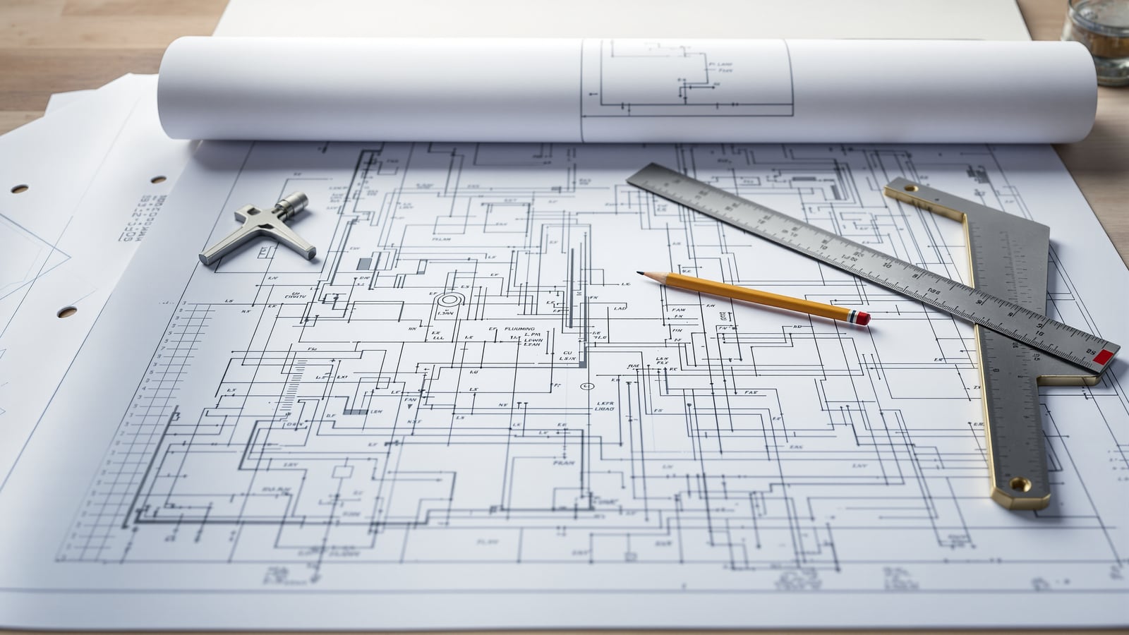
Plumbing Drawings for Indian Building Projects: How to Read and Prepare the Set
A practitioner's guide to the plumbing drawing set — layouts, risers, isometrics, details and as-builts — with symbol conventions, annotation basics and services coordination for Indian projects.
On most Indian projects the plumbing installed on site is only ever as good as the drawings it was built from. A clear, coordinated plumbing drawings set turns a designer's intent into something a contractor can price, a plumber can lay, and an inspector can verify. This guide is a practical walk-through of what that set contains, how to read each sheet, how to prepare and annotate it, and how it must talk to the architectural, structural and electrical drawings around it. It is a process guide — for the physics of pipes, pumps and traps, follow the pillars linked throughout.
Why the drawing set matters
A plumbing installation is buried in walls, chased into floors, dropped through shafts and cast into slabs. Once concrete is poured or tiles are laid, mistakes are expensive to undo. The drawing set is where those mistakes get caught — on paper — before they become site problems. It is also the single reference that the consultant, the main contractor, the plumbing subcontractor, the site engineer and the client's project manager all read from, so it has to be unambiguous.
Treat the drawing set as the contract for what gets built underground and behind walls. If it is not on the drawing, it will not reliably happen on site — and if it is drawn wrong, it will be built wrong.
Good drawings do three jobs at once: they describe the system, they let it be measured for a BOQ and tender, and they leave a record (the as-built) for whoever maintains the building for the next forty years.
The plumbing drawing set: what it contains
A complete set is not one drawing but a family of them, each answering a different question. The table below is a typical drawing-set index for an Indian building project — use it as a checklist when you issue or receive a set.
| Sheet / drawing type | What it shows | Question it answers |
|---|---|---|
| Cover sheet & drawing index | Sheet list, revisions, north point, legend reference | What is in this set, at what revision? |
| General notes & legend | Symbols, line types, abbreviations, specification notes | How do I read every other sheet? |
| Water supply layout (per floor) | Cold, hot and flushing pipe runs in plan, fixtures, valves | Where does each pipe run on this floor? |
| Drainage & vent layout (per floor) | Soil, waste and vent runs, gully traps, floor traps, gradients | How does waste leave this floor? |
| Riser / schematic diagram | Vertical stacks, tank feeds, pumps, floor-to-floor connections | How do the floors connect vertically? |
| Isometric drawings | 3D single-line view of a toilet group or stack | Exactly how is this cluster piped and vented? |
| Detail drawings | Toilet-shaft sections, tank rooms, pump rooms, trap details | How is this specific junction built? |
| External / site services | Underground drainage, manholes, water mains, RWH, STP tie-ins | How does the building connect to the outside? |
| As-built / red-line set | The system as actually installed | What is really in the ground and the walls? |
Layout (plan) drawings
Plan drawings are the workhorses — one per floor, drawn over the architectural floor plan (usually screened back to grey) so pipe runs read against rooms, walls and fixtures. Water supply and drainage are normally separate sheets, or clearly separated by line type, because overlaying every service on one plan becomes unreadable. Plans show horizontal runs, fixture positions, valve and clean-out locations, and pipe sizes called out along each run.
Riser diagrams and schematics
A riser diagram is a not-to-scale vertical schematic showing how floors stack and connect: the underground and overhead tanks, the pump set, the rising mains, each floor take-off, and the drainage stacks with their vents. It is the single sheet that lets you understand the whole building's water and waste logic at a glance — invaluable for a high-rise. See /guides/plumbing-systems-guide-india for the system logic these diagrams represent.
Isometric drawings
Isometrics are single-line 3D-style views, typically drawn at 30 degrees, of a discrete piece of the system — a single toilet, a toilet group, or one stack. They remove the ambiguity that plans and risers leave behind: exactly which pipe connects to what, in what order, with what fall and which vent. For a WC-plus-basin-plus-shower cluster, the isometric is where the plumber sees the true build sequence.
Detail drawings
Details are large-scale sections and blow-ups of the tricky bits: the toilet-shaft section, the pump-room piping, the underground tank, a gully trap, a waterproofing upstand at a floor trap. They are where the concealed-work decisions get pinned down — coordinate them with /guides/concealed-plumbing-india.
As-built and red-line drawings
During construction the plumber marks up a print in red ink wherever the installation departs from the issued drawing — a re-routed pipe, a relocated clean-out, an added valve. These red-line drawings are then formalised into the as-built set at handover. The as-built is the most valuable long-term document in the whole set, because it is the only one that tells the truth about what is actually buried where. Never let a project close without it.
Reading the sheet: symbols, line types and scale
Every plumbing drawing rests on a shared visual language. There is no single universal symbol number you should quote blindly — conventions vary between consultants and follow project standards and the drawing legend. Always read the legend on the general-notes sheet first, because that legend governs that set. The table below is a representative symbol and line-type legend of the kind you will meet.
| Element | Typical representation | Notes |
|---|---|---|
| Cold water supply | Solid line, labelled CW | Line weight/colour per project legend |
| Hot water supply | Long-dash line, labelled HW | Often a distinct colour on colour prints |
| Soil / waste pipe | Heavy solid line, labelled SW / WP | Drainage runs are usually the heaviest weight |
| Vent pipe | Dashed or dot-dash line, labelled V | Keeps vents legible against waste runs |
| Rising main / pumped line | Line with flow arrow | Arrow shows direction of flow |
| Valve (gate/ball) | Bow-tie or circle symbol | Type noted alongside |
| Floor trap / gully trap | Small square or circle with cross | FT / GT abbreviation |
| Clean-out / inspection eye | Circle with "CO" tag | Access point for rodding |
| Pipe drop / rise | Dot (drop) or arrow-and-tail | Reads the pipe going down or up through a slab |
| Fixture (WC, WHB, etc.) | Standardised plan symbol | Matched to the fixture schedule |
Line types carry as much meaning as symbols: continuous lines for the service being described, dashed for a different service or for pipe below/behind, and arrowheads for flow direction. Line weight creates hierarchy — the drainage you are describing is drawn heavy; the architectural background is screened light.
Scale matters because it sets how much can be shown. Floor-plan layouts are typically drawn at scales such as 1:100 or 1:50; toilet enlargements and details at 1:20 or 1:10; risers and isometrics are usually schematic and not to scale (marked NTS). Confirm the scale in every title block and never measure off a print reduced or enlarged from its stated scale.
Annotation ties it together: pipe sizes (nominal bore) called out on each run, invert or floor levels where relevant, gradients for drainage (expressed as a fall ratio), fixture tags cross-referenced to a schedule, and section markers pointing to the detail sheets. Keep annotation consistent across the set — the same abbreviation must mean the same thing on every sheet.
How the drawings develop through the project
Drawings are not issued once; they evolve through named stages, each with its own purpose and level of detail.
- Concept / schematic — single-line risers and block layouts to prove the strategy and inform loads. Ties to /guides/plumbing-planning-new-homes-india.
- Detailed design / GFC (Good For Construction) — the full coordinated set: layouts, risers, isometrics and details, sized and annotated, ready to build from.
- Tender / BOQ — the same drawings used to measure quantities; the drawing set and the BOQ must agree.
- Shop / construction drawings — the contractor's fabrication-level sheets, coordinated against site reality.
- As-built — the red-lined reality, formalised at handover.
A drawing labelled "for information" or "for tender" is not the same as "GFC" — never let a plumber build from anything but the current GFC revision. Track revisions rigorously: every sheet carries a revision number, a date and a description of what changed, and superseded prints must be withdrawn from site.
Coordinating with architecture, structure and electrical
This is where plumbing drawings earn their keep. A pipe does not live alone — it shares walls, floors, ceilings and shafts with structure, electrical, HVAC and fire services. Coordination means overlaying all services and resolving clashes on paper.
- Architectural coordination — fixture positions, tile setting-out, false-ceiling voids for concealed runs, wall thicknesses that must house a concealed pipe. Plumbing layouts are drawn over the architectural base for exactly this reason.
- Structural coordination — this is the critical one. Pipes cross beams and slabs, so you must agree sleeves (cast-in openings for pipes to pass through), cut-outs and shafts with the structural engineer before the slab is poured. A sleeve missed at casting means core-drilling later — costly and sometimes not permitted through a beam. Mark every slab penetration on a coordinated services drawing and get structural sign-off.
- Electrical and other services — maintain separation between water lines and electrical conduits/panels, and sequence who occupies a shared shaft or ceiling void. A services coordination drawing (a combined-services layout) is the deliverable that proves the clash-free routing.
- Shafts and service ducts — plumbing stacks live in dedicated shafts. The shaft must be sized on the drawings to hold every pipe plus access and future maintenance clearance, and its position must be consistent from the layout up through the riser.
Preparing a set: a working sequence
If you are producing the drawings, a reliable order keeps rework down:
1. Fix fixture positions with the architect and lock the toilet/utility layouts.
2. Set the riser strategy (tanks, pumps, stacks, shaft locations) as a schematic.
3. Draw the per-floor layouts over the architectural base, sizing and annotating runs.
4. Develop isometrics for each fixture cluster and stack.
5. Produce the detail sheets for shafts, tank and pump rooms, and traps.
6. Overlay all services, resolve clashes, and mark every sleeve and cut-out.
7. Compile the index, legend and general notes; issue as GFC with a clean revision block.
8. Through construction, collect red-lines; formalise the as-built at handover.
Quantities for tender come off this set — keep the drawings and the BOQ aligned, and point rates to current market or SOR figures via the cost guide rather than freezing numbers on the drawing.
Copy-ready plumbing drawings checklist
Lift this straight onto your next project:
- [ ] Drawing index and revision block complete; every sheet listed and dated.
- [ ] General-notes sheet carries a full symbol legend, line-type key and abbreviations.
- [ ] Per-floor water supply layouts: runs sized, valves and fixtures located.
- [ ] Per-floor drainage and vent layouts: gradients, traps and clean-outs shown.
- [ ] Riser / schematic diagram covering tanks, pumps, stacks and vents.
- [ ] Isometrics for each fixture cluster and stack.
- [ ] Detail sheets for shafts, tank room, pump room and key traps.
- [ ] External services: manholes, invert levels, mains and STP/RWH tie-ins.
- [ ] Scales stated in every title block; NTS marked where schematic.
- [ ] Combined-services coordination sheet with all clashes resolved.
- [ ] Every slab sleeve and cut-out marked and structurally signed off before pour.
- [ ] Shafts sized for all pipes plus maintenance access.
- [ ] Current GFC revision issued; superseded prints withdrawn from site.
- [ ] Red-line prints maintained during construction.
- [ ] As-built set formalised and handed over with the O&M documents.
Where to go next
- The whole plumbing system, end to end: /guides/plumbing-systems-guide-india
- Planning plumbing for a new home: /guides/plumbing-planning-new-homes-india
- Concealed plumbing and its details: /guides/concealed-plumbing-india
- The professional-resources pillar (checklists, templates, toolkits): /guides/plumbing-professional-resources-india
References
Cited by name and issuing body — always confirm current details at the official source and against the approved project specification:
- National Building Code of India 2016 (NBC 2016), Part 9 — Plumbing Services — Bureau of Indian Standards (BIS); the framework your local bye-laws draw upon.
- IS standards for plumbing symbols, drafting practice, pipes and fittings — Bureau of Indian Standards (BIS); read the legend on the actual set, and follow the project standard.
- CPHEEO manuals on water supply and sewerage — Central Public Health & Environmental Engineering Organisation, Ministry of Housing & Urban Affairs.
- Approved project specification and drawing standards — the governing legend, scales and conventions for your specific set.
Export this guide
Related Guides — Deep-dive reading
How All Construction Drawings Work Together
From one grid to a finished house — how architectural, structural and MEP sheets coordinate, where clashes hide, the order drawings are issued, and how a small change ripples across the whole set.
Construction DrawingsBathroom Planning for New Homes in India: Get It Right Before You Build
The bathroom decisions you cannot undo once the slab is cast — location and stacking, sunken vs non-sunken slabs, waterproofing, and the plumbing, electrical and ventilation you must coordinate with the civil work, stage by stage.
BathroomsBathroom Plumbing India: The Complete Guide to Water Supply, Drainage, Traps & Pipes
The whole plumbing picture for an Indian bathroom in one place — the two systems (cold and hot water supply, and waste/soil drainage with its vented SWV stack), traps and the floor trap, slopes and gradients, concealed vs exposed pipework, pipe materials (CPVC/UPVC/PEX/GI) and the overhead-tank pressure reality — with the coordination that must happen before any civil work starts.
BathroomsRelated Tools — Try Free
Rainwater Tank Sizer
How big should your rainwater tank be? Computes annual harvest, recommended tank capacity in litres, water-bill savings, and payback — for 10 Indian cities.
RWH CalculatorPlumbing Pressure-Test & Leak Checklist
Pre-closure pressure and leak test — 9 categories, 60+ checkpoints across water supply, drainage, fixtures, waterproofing, hot water, tanks.
Pre-Closure TestBathroom Drainage Pipe Calculator
Recommended drain and waste pipe sizes, slopes and stack size for a bathroom's fixtures — indicative IS 1172 / NBC plumbing practice.
Bathroom Calculator