
Fire-Alarm Device Schedule for India (2026): Every Detector, Zone and Address
A ready-to-adapt device schedule that lists every fire-alarm detector, call point, sounder and module against its location, its zone (conventional) or address (addressable), its loop and its panel — the record that drives panel programming, the cause-and-effect matrix, cabling and commissioning.
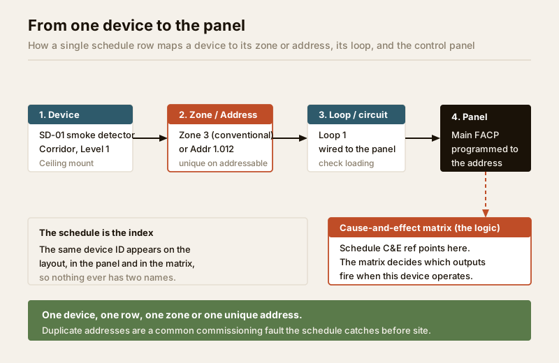
A fire-alarm system is only as good as the list that says what every device is, where it sits, and what the panel should do when it operates. That list is the fire-alarm device schedule: one row per physical device — each smoke, heat or multi-sensor detector, each manual call point, each sounder or strobe, each monitor, control or interface module — mapped to a location, a zone (on a conventional system) or an address (on an addressable one), a loop or circuit, and the panel it reports to. It is the single spreadsheet that ties the drawings, the panel programming, the cause-and-effect matrix, the cabling and the commissioning record together.
This resource is part of Studio Matrx's professional security resources toolkit and its how-to-use overview. It sits in the middle of the fire-system lifecycle: after the concept and zoning are set, the schedule captures every device the design calls for; during procurement it becomes the count that the tender and the delivery are checked against; at installation it is marked up as-built; and at commissioning it becomes the tested-and-signed record handed to the client and, in part, to the fire officer.
Scope & how to read this. This is a ready-to-adapt professional template, not authoritative, contractual or legal wording, and it does not set any life-safety requirement. Device selection, coverage, spacing, zoning, the cause-and-effect logic and the test criteria are fixed by the National Building Code (SP 7:2026), the product manufacturer and the fire officer or fire consultant on your project. The schedule RECORDS that design — it does not replace it. Verify every figure with your consultant and the Authority Having Jurisdiction (AHJ), and get professional review before it drives any procurement or contract.
Where the schedule sits, and what it feeds
Think of the device schedule as the master index that everything else references by device ID. Get the ID and the zone-or-address right, and four other documents fall into place:
- Panel programming. On an addressable panel, each device is programmed with the address in this schedule; on a conventional panel, each detection circuit is a zone. The schedule is the programmer's worksheet — see fire-alarm control panels.
- The cause-and-effect matrix. Each device (or its zone) is an input; the schedule's cause-and-effect reference points to the row in the matrix that says what outputs fire when that input operates. The matrix is set by the consultant and the fire officer, not by this list.
- Zoning and drawings. The zone column has to agree with the fire-alarm zoning plan and the layout drawings, so a device never appears in two zones or none.
- Cabling and power. The cable-type column flags where fire-survival (fire-resistant) cable is required so the cable fire-performance schedule and the loop/circuit loading agree.
The columns, explained
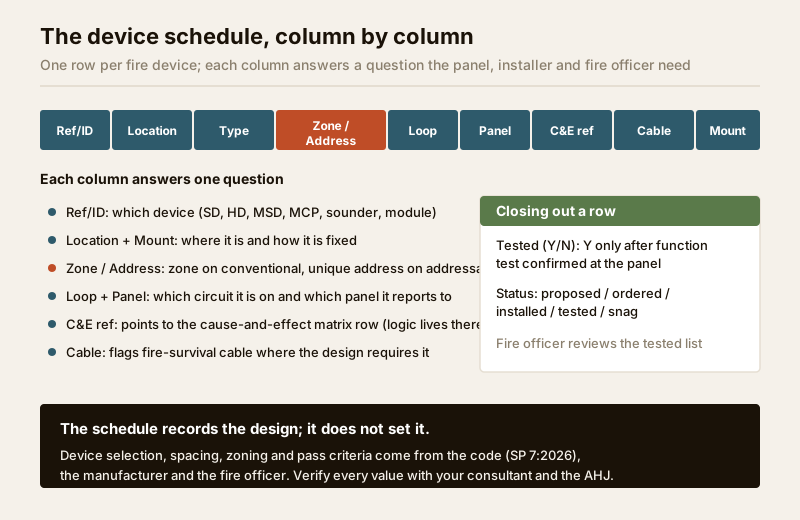
Keep one row per physical device. These are the columns that make the schedule useful to the programmer, the installer, the tester and the fire officer alike.
- Device ref / ID — a short unique tag, ideally typed: "SD" smoke detector, "HD" heat detector, "MSD" multi-sensor, "MCP" manual call point, "SD/ST" sounder or strobe, "MM" monitor module, "CM" control module, "IM" interface. Keep it stable from design through as-built.
- Location — plain-language position ("Corridor, Level 1, near lift lobby") plus a grid or drawing reference so it can be found on the layout.
- Device type — what the device is and the sensing principle where relevant (smoke, heat, multi-sensor). Smoke-versus-heat selection is a design decision set by the code and consultant, not by this table.
- Zone (conventional) / Address (addressable) — the heart of the schedule. On a conventional system this is the zone number the device sits in; on an addressable system it is the loop-and-address the device answers to. Fill the column that matches your system and leave the other marked "n/a".
- Loop / circuit — the loop (addressable) or detection circuit (conventional) the device is wired on, for loading and fault-finding.
- Panel — which control panel or repeater the device reports to (matters on networked or multi-panel jobs).
- Cause-and-effect ref — a pointer to the row in the cause-and-effect matrix for this input; do not restate the logic here.
- Cable type — the cable serving the device, flagging fire-survival cable where the design requires it; the actual specification is verified against the code and the cable schedule.
- Mounting — ceiling, wall, height or special mount (duct, void, high-level), so the installer and tester know where to look.
- Commissioned / tested (Y/N) — set to Y only when the device has been function-tested and its response confirmed at the panel during commissioning.
- Status — a working state: proposed, ordered, installed, tested, or snag.
Worked example device schedule
The rows below are illustrative only, to show the shape of a filled schedule. The zone numbers, addresses and cable notes are placeholders — replace every one with values from your own design.
Example only — adapt to your project. These device IDs, zones and addresses are generic and must not be treated as real coverage, spacing or addressing. Coverage, detector selection, zoning and the cause-and-effect logic come from SP 7:2026, the manufacturer and the fire officer. Verify each row with your consultant and the AHJ.
| Device ref | Location | Device type | Zone / Address | Loop / circuit | Panel | C&E ref | Cable type | Mounting | Tested (Y/N) | Status |
|---|---|---|---|---|---|---|---|---|---|---|
| SD-01 | Corridor, Level 1 | Smoke detector | Zone 3 / Addr 1.012 | Loop 1 | Main FACP | CE-03 | verify (fire-survival where required) | Ceiling | N | Installed |
| HD-01 | Kitchen, Level 1 | Heat detector | Zone 4 / Addr 1.018 | Loop 1 | Main FACP | CE-04 | verify | Ceiling | N | Installed |
| MSD-02 | Server room | Multi-sensor detector | Zone 5 / Addr 1.031 | Loop 1 | Main FACP | CE-05 | verify (fire-survival) | Ceiling | N | Ordered |
| MCP-01 | Level 1 stair lobby | Manual call point | Zone 3 / Addr 1.040 | Loop 1 | Main FACP | CE-01 | verify | Wall, exit route | N | Installed |
| SDR-01 | Corridor, Level 1 | Sounder / strobe | Zone 3 / Addr 1.055 | Loop 2 | Main FACP | CE-10 | fire-survival (verify) | Wall / high-level | N | Installed |
| MM-01 | Sprinkler flow switch | Monitor module | Zone 6 / Addr 2.008 | Loop 2 | Main FACP | CE-06 | verify | Riser, plant | N | Proposed |
| CM-01 | AHU shutdown relay | Control module | -- / Addr 2.014 | Loop 2 | Main FACP | CE-12 | fire-survival (verify) | Plant room | N | Proposed |
Notes columns like "verify" and "e.g." are deliberate: where a real cable grade, address or panel type belongs, the schedule says "specify" or "verify" until the consultant confirms it, so no placeholder is ever mistaken for a design decision.
Blank template — copy and adapt
Copy the header row and the placeholder rows into your project sheet and fill one row per device. Add repeater or per-panel tabs on larger jobs. Delete the worked-example values above and keep only your own.
| Device ref | Location | Device type | Zone / Address | Loop / circuit | Panel | C&E ref | Cable type | Mounting | Tested (Y/N) | Status |
|---|---|---|---|---|---|---|---|---|---|---|
| ... | ... | ... | ... | ... | ... | ... | ... | ... | Y / N | ... |
| ... | ... | ... | ... | ... | ... | ... | ... | ... | Y / N | ... |
| ... | ... | ... | ... | ... | ... | ... | ... | ... | Y / N | ... |
| ... | ... | ... | ... | ... | ... | ... | ... | ... | Y / N | ... |
A short header block above the table is worth keeping too: project name, building, panel make and type (conventional or addressable), number of loops or zones, the drawing revision the schedule matches, prepared-by, and checked-by. That header is how a fire officer or a future engineer knows which revision they are reading.
Conventional zones versus addressable addresses
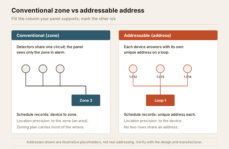
The one column that trips people up is the zone-or-address column, because it works differently on the two system types. Fill the column your panel supports and mark the other "n/a".
| Aspect | Conventional (zone) | Addressable (address) |
|---|---|---|
| What the schedule records | The zone number each device belongs to | The unique loop-and-address of each device |
| Panel sees | A zone in alarm | The exact device in alarm |
| Wiring | Detection circuits, one per zone (grouped) | Addressable loops, many devices per loop |
| Location precision | To the zone (a defined area) | To the individual device |
| Where to read more | Fire-alarm zoning | Addressable fire-alarm systems |
On a conventional system the schedule is essentially a device-to-zone list, and the zoning plan carries most of the "where". On an addressable system each row must have a unique address, and duplicate addresses are one of the most common commissioning faults the schedule helps you catch before you are on site.
How to use and adapt it
- Number before you draw. Assign the device IDs first and use the same IDs on the layout, the schedule and the panel, so nothing has two names.
- One device, one row, one zone-or-address. If a device appears twice, or in no zone, the schedule has found a design error early — fix it here, not on site.
- Keep it as-built. Positions and addresses shift during install. Mark the schedule up as work proceeds and reissue it as the as-built record at handover.
- Do not restate logic. The cause-and-effect reference points at the matrix; the matrix, owned by the consultant and the fire officer, is where the "what happens when" lives.
- Flag fire-survival cable, do not specify it here. The cable column signals where survival cable is required; confirm the grade against the cable fire-performance schedule and the code.
Life-safety: this schedule records the design, it does not set the standard. Which detector goes where (smoke versus heat versus multi-sensor), how far apart devices sit, how areas are zoned, what the cause-and-effect logic is, and what counts as a pass at commissioning are all determined by the National Building Code (SP 7:2026), the manufacturer's data and the fire officer or fire consultant — never by this template. Do not tune coverage, spacing or logic from a schedule; use the schedule to record what the code-compliant design specifies, and have that design signed off by your consultant and the AHJ.
How it connects to the other documents
The device schedule is one member of a family that a fire and security consultant hands over together:
- The zoning plan (fire-alarm zoning) defines the zones this schedule references.
- The panel and cause-and-effect (fire-alarm control panels) turn the device list into programmed inputs and outputs.
- The cable and power schedules (cable fire-performance requirements) take the cable-type and loop-loading flags from here.
- The wider equipment schedule for the non-fire security devices on the same project follows this same one-row-per-device shape.
- The testing checklist and the Fire NOC rely on the "tested (Y/N)" column: a device is only closed out when it has been function-tested and confirmed at the panel, and the completed schedule is part of the evidence the fire officer reviews.
Completion checklist
- Every device has a unique ID, and the same ID appears on the layout and at the panel.
- Every row has a zone (conventional) or a unique address (addressable), never both blank and never a duplicate address.
- Loop or circuit loading has been checked against the panel and cable design.
- Each cable-type cell is filled or marked "verify", with fire-survival flagged where the design requires it.
- Each row links to a cause-and-effect reference in the matrix.
- The header block records the panel type, loop/zone count, drawing revision, prepared-by and checked-by.
- No placeholder value (a zone, address, cable grade or model) has been left in as if it were real.
- The completed, as-built schedule is signed off by the consultant and available for the fire officer at commissioning.
References
- National Building Code of India (SP 7:2026), Bureau of Indian Standards — the authority for fire detection and alarm design, device selection, zoning and testing. Verify the current edition and clauses with your consultant; confirm status at https://www.services.bis.gov.in/
- Manufacturer documentation for your specific panel and devices — the authoritative source for addressing, loop loading, mounting and function testing; follow it over any generic guidance.
- The fire officer / Authority Having Jurisdiction and your fire consultant — the final word on coverage, cause-and-effect and acceptance criteria for your building.
This is an educational template to adapt, not authoritative, contractual or legal wording, and it sets no life-safety requirement. Fire-alarm design, installation and commissioning are qualified professional tasks — engage a competent fire consultant and licensed installer, and defer all specifics to the code, the manufacturer and the AHJ.
Export this guide
Related Guides — Deep-dive reading
Fire Alarm Testing Checklist for India (2026): A Record, Not the Rulebook
A ready-to-adapt checklist to record the testing of a fire alarm and detection system at commissioning and periodically — with the loud reminder that the code (NBC, SP 7:2026), the manufacturer and the fire officer set the actual scope, methods, pass criteria and frequencies, not this sheet.
SecurityAddressable Fire Alarm Systems in India (2026): Loops, Exact Location & When You Need One
The system for larger, complex buildings where you must know exactly which device triggered - how the loop and unique device addresses work, when the Fire NOC demands one, and how to specify it well.
SecurityHow to Choose a Fire Alarm in India (2026): A Life-Safety, Code-Governed Buying Guide
A fire alarm is not shopped on price or looks. It is specified to the National Building Code and the local fire officer, built from listed and certified parts, and installed by a licensed contractor. This guide shows a homeowner, manager or architect how to choose and verify one correctly.
SecurityRelated Tools — Try Free
CCTV Commissioning & Handover Checklist
An interactive go/no-go checklist to run at handover — cameras day and night, recording, alerts, passwords and documents — before you clear the final bill.
Handover ChecklistInterior Contract Clause Checklist
16 sections and 98 checkboxes covering scope, BOQ, milestones, penalties, warranty, and disputes.
Contract ChecklistContract Studio
AI generates professional architecture service agreements with milestones and scope.
ArchitectAI