
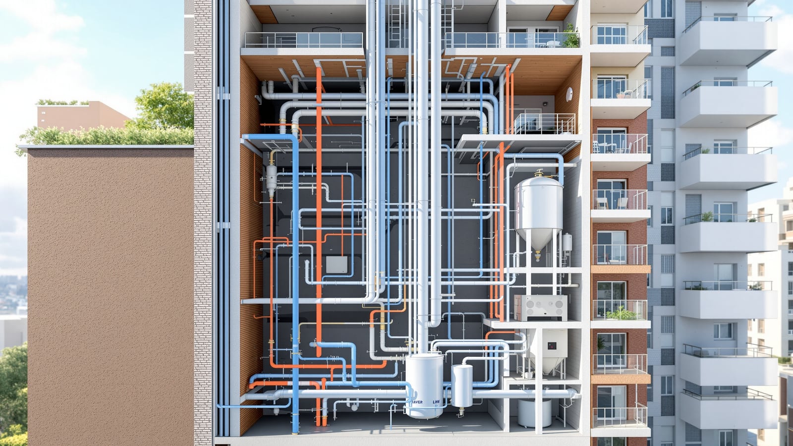
High-Rise Plumbing Systems (India): Pressure Zoning, Boosters & Tall Stacks
A professional, India-first deep dive into plumbing for towers and multi-storey buildings — the pressure problem, vertical pressure zoning, break-pressure tanks, hydro-pneumatic and booster pumps, pressure-reducing valves, and tall soil, waste and vent stacks with offsets.
A twenty-storey tower is not a bungalow stacked twenty times — it is a pressure-management problem wearing a plumbing costume. Once a building climbs past roughly seven or eight floors, the static head of a single water column becomes both your friend and your enemy: it gives you gravity flow for free, but it also blows out taps, cracks fittings and hammers pipes on the lower floors. This Studio Matrx guide goes a level deeper than our building-services pillar on exactly this problem — how to zone, break, boost and drain a tall building in India.
If you want the whole-building overview first, read the Building Plumbing Services Guide and the flagship Plumbing Systems Guide. For shorter blocks, our Low-Rise Plumbing Systems guide is the right companion — this one assumes you are working on a genuine high-rise.
The pressure problem in tall buildings
Water pressure in a static column rises about 1 bar for every 10.2 m of height — roughly 0.1 bar per metre, or close to 1 bar per three floors at a typical 3 m to 3.3 m floor-to-floor. In old plumbing shorthand, every 30 ft of drop adds about 13 psi.
Now run the arithmetic on a downfeed tower fed from an overhead tank. A fixture on the ground floor of a 20-storey building sits perhaps 60 m below that tank. Ignoring friction, it sees about 6 bar of static pressure. Meanwhile the flush valve, the mixer cartridge and the diverter it feeds are all rated for a fraction of that.
Two hard limits define the window you must design inside:
- Maximum static pressure at a fixture should stay around 3 to 4.5 bar (NBC and most fixture makers cluster here). Above roughly 5 bar you get spray, splash, water hammer, premature cartridge failure and noisy pipes — and you waste water.
- Minimum residual (flow) pressure at the highest, farthest fixture must stay above the fixture's need — commonly 0.5 to 1 bar for taps, but 1.5 to 2 bar or more for a rain shower, an instant geyser or a flush valve.
| Height above fixture | Approx. static pressure | Practical meaning |
|---|---|---|
| 5 m (~1-2 floors) | ~0.5 bar | Minimum for many taps; weak for showers |
| 10 m (~3 floors) | ~1.0 bar | Comfortable tap flow |
| 20 m (~6-7 floors) | ~2.0 bar | Good showers; upper edge for comfort |
| 35 m (~11 floors) | ~3.5 bar | At the fixture-rating ceiling |
| 45 m+ (~15 floors) | ~4.5 bar+ | PRV territory — protect the fixtures |
| 60 m (~20 floors) | ~6.0 bar | Well beyond fixture limits — must be broken |
The whole discipline of high-rise plumbing is keeping every single fixture inside that ~1 to 4.5 bar band, no matter where it sits in a 60 m to 150 m column. You cannot do it with one tank and one riser. You do it by breaking the column into zones.
Pressure zoning: break the column every 5-7 floors
The core principle is simple: never let an uninterrupted water column exceed the height that produces safe fixture pressure. In practice, designers cap a single pressure zone at about 5 to 7 floors, i.e. roughly 15 m to 22 m of vertical run, so the bottom fixture of each zone sees around 2 to 3.5 bar static and never approaches the danger line.
There are three ways to establish zones, and real towers usually mix them:
- Downfeed from an overhead tank, zoned by PRVs. One high tank feeds the whole tower; each 5-7 floor band gets a pressure-reducing valve on its riser tap-off so the lower zones are protected. Cheapest to build, but a single PRV failure exposes a whole zone.
- Downfeed with intermediate break-pressure tanks. The column is physically interrupted every several floors by a mid-level tank open to atmosphere, which resets static pressure to zero at that level. Most robust, but it eats floor area and adds structural load.
- Upfeed by hydro-pneumatic or zoned booster pumps. Pumps push water up from a low-level tank and hold each zone at a set pressure. Common in modern Indian towers where a full overhead tank is undesirable.
Rule of thumb: size each zone so the lowest fixture in it stays under ~4.5 bar and the highest fixture stays above its minimum flow pressure. If those two numbers cannot both be met, the zone is too tall — split it.
The diagram below shows a single downfeed tower zoned three ways: a break-pressure tank resetting the column mid-height, and PRVs trimming the sub-zones below it.
Break-pressure and mid-level tanks
A break-pressure tank (also called a break tank or intermediate storage tank) is an open, vented vessel placed part-way up the tower. Water arrives, fills it, and leaves under a fresh, short static head measured only from that tank — not from the roof. It breaks the column, resetting pressure to atmospheric.
Where they earn their keep:
- Very tall towers where even zoned PRVs would sit above their comfortable turndown ratio.
- Refuge-floor or service-floor levels, which many Indian high-rises already provide at intervals — a natural home for a mid-level tank.
- Buildings where you want each zone hydraulically independent, so a fault in one does not drain or over-pressurise another.
The trade-offs are real: a break tank consumes floor area, adds dead and live structural load (a cubic metre of water is a tonne), needs its own float control and overflow, and introduces a second free water surface to keep clean. Size the volume for the zone's peak flow plus a short buffer, not for a full day's storage — that is what the low-level and terrace tanks are for.
Hydro-pneumatic systems
A hydro-pneumatic system replaces (or supplements) the overhead tank with a pressure vessel and a pump set. The vessel holds a cushion of compressed air over water; the pumps top it up. As fixtures draw, the air cushion maintains pressure between a cut-in and cut-out setpoint, so you get steady pressure without a tall gravity column.
Why Indian developers increasingly favour them:
- No large overhead tank competing for premium terrace real estate or adding rooftop load.
- Tight, tunable pressure band — ideal for uniform shower performance across floors.
- Naturally paired with variable-frequency drives (VFDs), which ramp pump speed to demand, saving energy and softening starts.
The catch: hydro-pneumatic sets are fully power-dependent. Lose the mains and the DG both, and the tower loses water — whereas a gravity overhead tank keeps flowing. Most designs hedge by keeping a smaller overhead tank for fire and emergency domestic reserve, and running domestic supply hydro-pneumatically below it.
Transfer pumps, booster pumps and PRVs
Three pump-and-valve roles do the vertical heavy lifting. Do not conflate them:
- Transfer pumps move water in bulk from the underground tank (UGT) to overhead or mid-level tanks. They are sized for fill time and lift, not for fixture pressure — they run intermittently on tank floats.
- Booster pumps (including hydro-pneumatic sets and zone boosters) provide fixture pressure to a zone in an upfeed or supplemented system. They run on demand and must hold a steady head.
- Pressure-reducing valves (PRVs) do the opposite — they throttle excess pressure down to a safe setpoint on downfeed risers and zone tap-offs. Every zone whose static pressure would exceed ~4.5 bar needs one.
| Device | Job | Sizing driver | Typical setpoint / duty |
|---|---|---|---|
| Transfer pump | UGT to OHT / mid-tank | Flow (L/min) and lift (m) | Runs on float; fills tank |
| Booster / hydro-pneumatic | Add pressure to a zone | Demand flow + required head | Hold ~2.5-4 bar band |
| Zone PRV | Reduce downfeed pressure | Inlet pressure and flow | Set outlet ~3-3.5 bar |
| Terrace / OHT | Gravity reserve + fire | Storage volume (day + fire) | Static, by height |
A few professional habits worth building in:
- Duty and standby. Every critical pump gets a standby of equal rating on auto-changeover. A tower with a single booster is a tower with a single point of failure.
- Design the PRV turndown. A PRV asked to drop 6 bar to 3 bar at low flow will chatter and wear. Where the ratio is large, stage two PRVs in series or add a break tank instead.
- Water hammer. Fast-closing solenoids and flush valves on a boosted riser demand air chambers or arrestors near the fixtures, and slow-closing or soft-start pump control at the plant.
- Metering and daily demand. Size storage and pumps to a realistic 135 lpcd domestic demand (per CPHEEO), adding institutional and flushing loads separately, and confirm against local bye-law minimums.
For everything downstream of the toilet — treatment, recycling and disposal — this guide hands off to the STP hub rather than repeating it. See STP for high-rise buildings for how tower sewage is treated and reused, including dual-plumbing for flushing.
The tall soil, waste and vent stack — with offsets
Drainage in a high-rise is not just a bigger downpipe. A tall soil and waste stack carries a fast-moving annular sheet of water and air; if the air side is not managed, the moving water siphons the traps on intermediate floors and foul air enters flats. The venting system is what keeps every trap sealed.
Key principles for the vertical drainage system:
- Two-pipe or single-stack-with-vent. Modern Indian towers commonly use a properly vented single-stack or a fully vented two-pipe system. Provide a vent stack running parallel to the soil stack, cross-connected at intervals, so the stack pressure never swings enough to break a trap seal.
- Stack sizing by drainage fixture units (DFU). Size the soil stack from the accumulated DFU load and the number of floors it serves, per NBC Part 9 / IS tables — an oversized dry stack de-primes traps; an undersized one floods.
- Terminate vents above the roof, clear of terraces, tanks and occupied openings, and never let a vent double as a rainwater outlet.
Offsets are where tall stacks get their reputation. When a stack must jog horizontally to dodge a column, transfer to a shaft or land on the treatment inlet, that horizontal run disrupts the falling flow, spikes pressure below it and can flood the offset:
- Keep offsets as few as possible; a straight stack is a happy stack.
- Where an offset is unavoidable, use two 45° bends rather than a single 90°, maintain drainage slope through the horizontal leg, and treat the run as a horizontal drain for sizing.
- Relieve the pressure surge: provide a relief vent connecting the stack just above and below the offset, so the trapped air can escape rather than blow trap seals on the floors nearby.
- Below a large offset, keep fixture branch connections a safe distance away — the zone just under an offset is a high-turbulence, high-pressure region.
The diagram contrasts a clean straight stack with a properly detailed offset.
Bringing it together on a real tower
A workable domestic-water strategy for a typical 20-storey Indian residential tower:
1. Underground tank (UGT) stores the day's demand plus fire reserve; transfer pumps lift to a terrace tank and possibly a mid-level break tank on the service floor.
2. Top zone feeds by gravity from the terrace tank; middle and lower zones feed from the break tank and through zone PRVs, so no fixture exceeds ~4 bar.
3. Where the developer skips a large overhead tank, a hydro-pneumatic set with VFD and standby holds the domestic zones, with a small OHT retained for fire and emergency reserve.
4. Drainage runs a vented stack per shaft, straight wherever possible, with relief-vented 45° offsets only where the structure forces a jog.
Every number here is indicative. Fixture ratings, PRV setpoints, DFU tables, tank volumes and local storage minimums must be confirmed against NBC 2016 Part 9, the relevant IS pipe and fitting standards, your fixture manufacturers' data, and your city's development-authority bye-laws — with a licensed plumbing engineer signing the hydraulics. Studio Matrx guides give you the model; the local code gives you the numbers.
For the layer above this — how these systems coordinate with electrical, HVAC and fire in the shafts — return to the Building Plumbing Services Guide.
References
- National Building Code of India (NBC) 2016, Part 9 — Plumbing Services (water supply, drainage, and sanitation provisions).
- CPHEEO Manual on Water Supply and Treatment and CPHEEO Manual on Sewerage and Sewage Treatment, Ministry of Housing and Urban Affairs (design demand such as 135 lpcd, storage and drainage guidance).
- Bureau of Indian Standards (IS) codes for pipes, fittings and plumbing practice, referenced within NBC Part 9 (confirm the current edition for each material before specifying).
- Local municipal and development-authority building bye-laws for storage, dual-plumbing and approval requirements (binding overlay — always verify).
Export this guide
Related Guides — Deep-dive reading
Bathroom Plumbing Code India: NBC 2016 Part 9, UPC-I & the IS Standards That Govern Pipework
A professional reference to the codes and standards that govern bathroom plumbing in India — the National Building Code (NBC 2016) Part 9 on Plumbing Services, the Uniform Plumbing Code India (UPC-I), the CPHEEO Manual, and the IS standards for water supply, drainage, trap seals, pipe sizing, slopes and venting — with a caveat to always verify the current code and your local authority.
BathroomsLow-Rise Plumbing Systems in India: Houses, Villas & Buildings up to 4 Storeys
How plumbing is organised for independent houses, villas and low-rise buildings up to about four storeys — the simple overhead-tank gravity model, when a small booster is still worth adding, single- versus multi-floor distribution, and the simpler stack and venting a low building can get away with.
PlumbingBuilding Plumbing Services Guide (India): MEP-Grade Water, Drainage & Riser Design
A professional, India-first reference to plumbing engineering for larger and commercial buildings — integrated design with MEP, multi-storey water distribution, and drainage and venting stacks.
PlumbingRelated Tools — Try Free
Rainwater Tank Sizer
How big should your rainwater tank be? Computes annual harvest, recommended tank capacity in litres, water-bill savings, and payback — for 10 Indian cities.
RWH CalculatorCross-Ventilation Analyzer
Estimate airflow and air changes per hour (ACH) from room size, window areas, layout, and local wind — with NBC 2016 Part 8 compliance check.
Ventilation CalculatorShower Pump Calculator
Check whether your shower needs a pressure-boost pump and what size — available vs required pressure from your tank height or supply.
Bathroom Calculator