

Orthographic Projection & Solids
How plan, elevation and section are really made.
Every plan, section and elevation is an orthographic projection — and there is a precise geometry beneath it, worked out by Gaspard Monge over two centuries ago. Learn that geometry and the drawings stop being conventions to memorise and become something you can reason about.
Learning objectives
By the end of this lesson, you will be able to — mapped to the course outcomes for Building Materials & Construction I:
Explain orthographic projection and why three views fix an object.
Distinguish first-angle from third-angle and place the views correctly.
Project simple solids and find the true shape of a section.
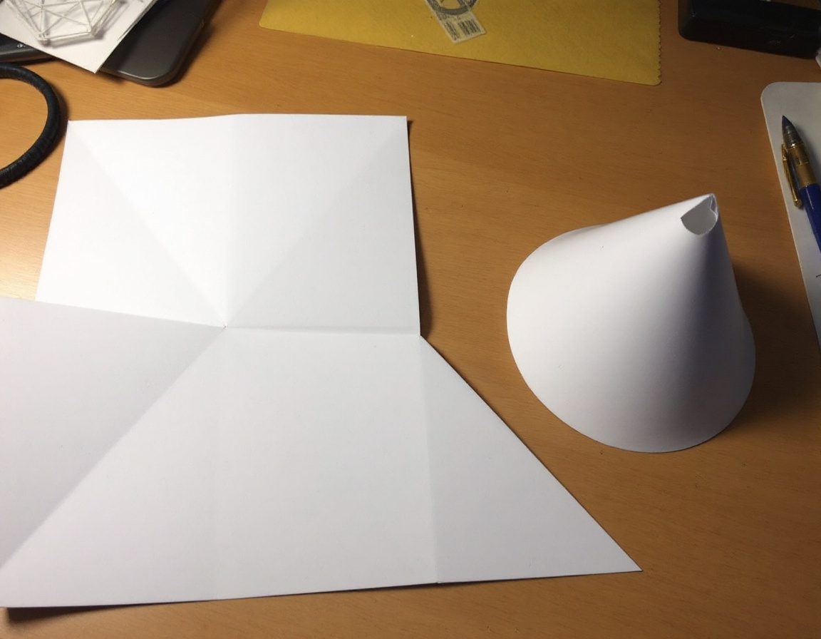
Develop the surface of a cone or prism into a flat pattern.
The principle, and first vs third angle
This is the constructed theory beneath the freehand plans and sections you draw in Design Drawing. Select a topic.
Multiview projection
Parallel projectors strike the plane of projection at 90°, so faces parallel to the plane appear true. The three principal planes (horizontal, vertical, profile) give plan, front elevation and side elevation. One view fixes only two dimensions — you need three to be unambiguous.[1]
Sections & development
A cutting plane reveals the interior and a true shape; unfolding a surface gives a flat pattern to cut and fold. Cones and cylinders develop exactly — a sphere never can.[2, 3]

The geometry beneath it all
All of this rests on descriptive geometry, devised by Gaspard Monge (kept a French military secret, published 1799) to represent 3-D objects in 2-D by systematic projection. Its two core problems — the true length of a line and the true shape of a plane — are exactly what auxiliary views and sections recover. CAD did not replace it; it automated it.[4]
Self-assessment
1. In FIRST-angle projection, the plan (top view) is placed:
2. The 'true shape' of a section is found by:
3. Which surface CANNOT be developed (flattened) without distortion?
Recap
References & further reading
- [1]Multiview orthographic projection — principle, the four quadrants, first vs third angle, the symbol. https://en.wikipedia.org/wiki/Multiview_orthographic_projection
- [2]Projection and sections of solids; true shape of section; hatching. Brainkart. https://www.brainkart.com/article/Projection-of-Solids-and-Section-of-Solids_6520/
- [3]Developable surfaces — cylinders/cones develop; spheres cannot (Gaussian curvature). https://en.wikipedia.org/wiki/Developable_surface
- [4]Gaspard Monge and the origin of descriptive geometry (Géométrie descriptive, 1799). Britannica. https://www.britannica.com/biography/Gaspard-Monge-comte-de-Peluse
Further reading
- Bhatt, N.D. (2014). Engineering Drawing — Plane and Solid Geometry (53rd ed.). Anand: Charotar — Orthographic Projection, Projection of Solids, Sections, Development.
- Paré, E.G., Loving, R.O. & Hill, I.L. Descriptive Geometry. New York: Macmillan / Prentice Hall.
- Monge, G. (1799). Géométrie descriptive. Paris — the founding text of the discipline.
Sources gathered and fact-checked June 2026. Published values vary by source, sample and method — treat as indicative and confirm against the cited standard before structural use.
The author
Amogh N P
Architect, interior designer, and creative polymath. Studio Matrx began in his notebooks — his vision of design made honest, useful, and open to everyone. Its Academy is written and taught in his memory, and free, forever.
More about Amogh →