
 Lesson 6.3
Lesson 6.3 · Designing for Robots & Printing
Computational & Parametric Workflows
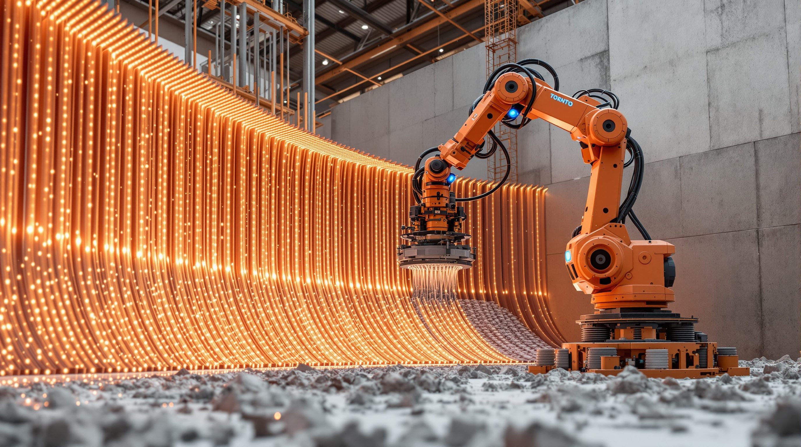
These buildings are rarely drawn line by line - they are designed as rules, parameters and algorithms that generate geometry and feed it straight to the machine, which is exactly why computational and parametric design and robotic fabrication grew up together and are now almost inseparable
How do you design a facade of a thousand different panels, each tuned to the sun, and hand it to a machine without drawing a thousand drawings? You do not draw the panels. You write the rule that makes them.
Imagine being asked to design a screen wall whose openings grow larger toward the top to catch more light, where every one of four hundred apertures differs slightly from its neighbours, and then to produce the fabrication data for a robot to make each unique piece. Drawing that by hand, panel by panel, would be maddening and error-strewn, and a single change to the brief would mean starting over. This is not an edge case in robotic fabrication; it is the normal case. The freedom to vary and complexify that the last lesson celebrated is only usable if there is a way to design that does not collapse under its own variation.
That way is computational and parametric design. Instead of drawing the final geometry directly, you define the design as a set of parameters (the inputs you can tune - spacing, angle, height, thickness) and rules or algorithms (the relationships that turn those inputs into geometry). The model generates the four hundred apertures from the rule; change the rule or a parameter and the whole design updates at once; and crucially, the same computational model that generates the geometry can generate the fabrication data that drives the machine. This is why robotic fabrication and computational design are not two separate skills that happen to be used together - they are two ends of one continuous workflow, and understanding that link is central to understanding how these buildings are actually made.
Don't draw the shape - write the RULE. Parameters + rules -> families of geometry -> fabrication data -> machine. Parametric (you author) / generative (computer proposes, you judge). Geometry, not guarantees.
Why fabrication and computation grew up together
The deep reason robotic fabrication and computational design are inseparable is that both speak the same language: explicit, machine-readable geometry. A machine cannot act on a hand sketch or a designer's intention; it needs geometry defined precisely enough to generate a toolpath. Computational design produces exactly that - geometry built from unambiguous rules and numbers. The output of a computational model is not a suggestive drawing but a definite, complete description of form that can flow downstream into fabrication data with no human re-interpretation. The two technologies fit together because one produces what the other consumes.
There is a historical and practical logic too. The freedoms robotic fabrication unlocks - complexity and variation at low cost - are precisely the things that are impossible to exploit with conventional drawing. If every part can be different, you need a way to design that does not require drawing every part; if complex curved form is affordable to build, you need a way to design complex curved form that does not require plotting every point by hand. Computational design is that way. So the capability of the machine created a demand for a new way of designing, and the two developed together: the history of digital fabrication in architecture is also the history of computational and parametric design tools. You rarely find one without the other.
This is why 'fabrication-literate' and 'computationally literate' have become almost the same thing for a designer working in this space. To design a varied, complex, machine-made element and actually get it built, you need to think in terms of rules and parameters that both generate the form and produce the fabrication output. A designer who can only draw fixed shapes by hand is limited to what can be drawn by hand - which throws away most of what robotic fabrication is good for. The link runs the other way too: computational design without a fabrication endpoint can drift into pretty but unbuildable geometry, while fabrication grounds it in what can actually be made.
A note on scope and honesty: this lesson teaches the shape of the workflow and why it matters, not a specific software tutorial, and it does not turn a designer into a structural engineer. The computational model can generate geometry and fabrication data; it does not certify that the result is strong, reinforced or code-compliant. Those remain, as always, the province of qualified engineers, certified testing, the manufacturer's verified data and the governing codes.
Parametric design: rules, parameters and families
Parametric design is the foundational idea, and it is simpler than the jargon suggests. Instead of drawing a shape as fixed coordinates, you define it by its parameters and the relationships between them. A parametric column is not 'a cylinder 400mm across and 3m tall drawn here'; it is 'a column whose diameter is a function of the load it carries and whose height reaches from this floor to that beam'. Change the load or move the beam, and the column updates itself, because it was defined by rules, not fixed points. The design is a recipe, not a photograph.
This unlocks three things that matter enormously for fabrication. The first is effortless variation: because the form comes from a rule, applying the rule with different inputs produces a whole family of related but distinct parts - the thousand different panels, each generated from the same logic with different parameters. This is how mass customisation is actually achieved in practice; the rule is authored once, the variants are generated automatically. The second is change without redrawing: because everything is related, a change to a parameter or a rule ripples through the entire model, so the design can be explored, tuned and corrected quickly - and the fabrication data regenerates with it. The third is embedded constraints: you can build the fabrication limits into the rules themselves, so the model only ever generates geometry that respects, say, the overhang angle or the envelope - designing with the grain by construction rather than by after-the-fact checking.
In practice this is done in visual or code-based environments - the best known in architecture being Grasshopper (a visual programming tool inside the Rhino modeller), alongside other node-based and scripted tools, and the parametric capabilities built into BIM software. The designer assembles a graph of operations: inputs feed components that generate and transform geometry, and sliders or data drive the parameters. It is a genuine shift in skill - closer to a blend of designing and light programming - but it is learnable, and it is increasingly a core literacy rather than an exotic specialism.
The honest caveat is that parametric power can become parametric self-indulgence: elaborate models that generate dazzling geometry disconnected from any real need, buildability or budget. A parametric model is only as good as the thinking behind its rules, and the same discipline from the last lesson applies - the variation and complexity it makes easy must still earn their place, and the binding engineering still sits with the engineers.
Parametric = design the RULE, not the shape. Parameters (sliders) + relationships -> a family of geometry. Change a parameter, the whole model + fab data update.
Generative and computational design: the machine proposes
If parametric design is authoring a rule and tuning its inputs yourself, generative design goes a step further: you define the goals and constraints, and let the computer generate and evaluate many candidate solutions, searching the design space for ones that perform well. You tell it what you want (minimise material, carry this load, maximise daylight, stay within these limits) and it proposes options - sometimes forms a human would never have drawn - which you then judge and refine. The designer shifts from drawing the answer to framing the problem and choosing among machine-generated answers.
This matters for fabrication in two ways. First, the performance-tuned, often organic forms that generative design produces - material concentrated exactly where load flows, lattices and voids where material is not needed - are frequently only buildable by additive fabrication, because conventional construction could not economically make such complex, optimised geometry. Generative design and robotic fabrication are therefore natural partners: the one proposes forms that only the other can build. Second, because the generative process already works from explicit geometry and quantified goals, its output can flow into the same fabrication chain - the optimised form becomes a toolpath.
It is worth being precise and sober about the terms, because they attract hype. 'Computational design' broadly means using computation as an active part of designing, of which parametric and generative design are the main strands. 'Generative design' specifically means algorithmically generating and evaluating many options against goals. And the newer wave of AI-assisted generative tools can propose options faster and from looser prompts - genuinely useful, and genuinely over-sold. In every case the computer is generating and evaluating geometry and performance; it is not exercising engineering judgement, guaranteeing safety, or accounting for everything a real building must satisfy. A generatively optimised structural form is a proposal, not a verified structure.
So the competent stance mirrors the rest of the course: use these tools to explore a vast design space and to generate forms tuned to real performance and makeable by the machine, while keeping a human designer's judgement firmly in charge of what is actually good, appropriate and buildable - and keeping every binding structural, reinforcement, material and code question with the qualified engineers, certified testing, the manufacturer's data and the governing codes. The algorithm widens your options; it does not replace your judgement or the engineer's.
From parameters to machine: the workflow end to end
Put the pieces together and a characteristic workflow emerges, worth seeing as a whole because it is how these projects actually run. It begins with intent and parameters: the designer frames what the element must do and identifies the variables - the spacing, angles, thicknesses, performance targets. Next, a parametric or generative model turns those into geometry: a rule-based definition generates the form (and a family of variants), often with the fabrication constraints - overhang, envelope, layer logic - built into the rules so the output is buildable by construction. Along the way the design is evaluated - against daylight, structure-as-indicator, material use, cost - and tuned, the parameters adjusted until the form performs and pleases.
Then the model produces fabrication data. This is the pivot from design to making: the geometry is sliced into layers, toolpaths are generated, and machine instructions (G-code or a robot program) are written - almost always automatically, from the same digital model, which is the whole point. Because the geometry was defined computationally and explicitly, this translation can be clean and direct, with no human redrawing. The data goes to the machine - the printer or robot arm - which executes it to produce the physical element. The next lesson follows this digital-to-physical chain in detail, including where it is fragile; here the point is simply that computational design and fabrication are the two ends of one connected pipeline.
The power of this is real: a change upstream (a new parameter, a revised rule, a different generative goal) can propagate all the way down to new fabrication data with little manual rework, which is what makes variation and iteration affordable. Often this sits within or alongside a BIM model, connecting the fabrication workflow to the wider coordination of the building. This integration - design, analysis, fabrication data and coordination sharing one digital model - is much of what 'digital fabrication' and 'file-to-factory' really mean.
Two honesties to close. First, the clean pipeline is an ideal; in reality there are breaks, translations, manual fixes and tolerances at every hand-off (the subject of the next lesson), and the chain is only as strong as its weakest link. Second, and unchanging: the computational model generates geometry and fabrication data, not guarantees. Whether the designed and generated element is structurally safe, properly reinforced, and compliant with code is determined by qualified structural engineers, material specialists, certified testing, the manufacturer's verified data and the governing codes (NBC India and local regulations). The workflow is a powerful way to design and make complex, varied, buildable form - not a substitute for the engineering and approval that make it a real, safe building.
Structural design & testing
Whether a computationally generated form is safe
A parametric or generative form, however optimised, is a proposal until a qualified structural engineer designs it and certified testing confirms it. Computation informs, it does not certify. Module 8.1.
Reinforcement strategy
Tensile strength in generated printed geometry
The central unsolved problem of 3DCP is not solved by a clever model; how to reinforce a generated form is the engineer's decision. Module 4.3.
Fabrication constraint data
The limits built into the rules (overhang, envelope, layer height)
The numeric limits encoded in a parametric model must come from the manufacturer's verified machine and material data, not assumed values, and be confirmed for the actual machine. Module 4.2.
Codes, standards & approval
Legal use of computationally generated forms
Novel generated geometry is approved via the governing codes (NBC India), the authority and the engineer - the model does not confer compliance. Module 8.2.
Workshop — write the rule, not the shape
You can grasp parametric thinking without any software by doing on paper what a parametric model does in code: defining a rule and a parameter, then generating a family of outputs by varying the input. This workshop builds the mental model that underlies every computational fabrication workflow.
Grid paper and a pencil is enough. If you want to go further, install a node-based tool such as Grasshopper and rebuild your rule - but the concept is the goal, not the software.
Goal: think in rules and parameters instead of fixed shapes
Inputs: a simple element to 'parameterise' (a louvre screen, a baluster run, a perforated panel), this lesson, grid paper
Time: ~45 minutes
- 1Choose your element and identify its parameters: what could vary? (e.g. louvre angle, spacing, depth). Pick one or two as your variables.
- 2Write the rule in plain words: state how the geometry is produced from the parameters and from a real driver (e.g. 'louvre angle = steeper where the sun is higher'). This is your algorithm, in English.
- 3Generate a family by hand: draw the element three times with three different parameter values (or across a gradient), following your rule exactly. You are doing what the model would do.
- 4Build in a constraint: add a fabrication limit to your rule (e.g. 'overhang never exceeds the safe corbel angle', 'each part fits within size X') and redraw so the rule only ever produces buildable geometry.
- 5Reflect: note how a single change to the rule would change all the variants at once, and write down which questions (strength of the generated form, reinforcement, code) you would still send to the engineer - the model generates geometry, not guarantees.
You’ll walk away with
A one-page 'parametric sketch': the parameters, the rule in plain words (including a fabrication constraint), a hand-generated family of three variants, and the note of deferred engineering questions. It is the thinking behind every parametric fabrication model, made visible.
Three altitudes on the same idea
Read the band that fits you — or all three.
To design seriously for robotic fabrication at building scale, computational and parametric thinking is no longer optional - it is the medium. Designing a varied, complex, performance-tuned element and getting it built means defining it as rules and parameters that both generate the geometry and feed the fabrication data, rather than drawing fixed shapes by hand. Build the fabrication constraints into your rules so the model generates buildable form by construction; use generative tools to explore forms tuned to real performance; and keep the pipeline connected, often within BIM, so a change upstream flows to new fabrication data. Keep human judgement in charge of what is actually good and appropriate, make complexity earn its place, and remember the model generates geometry, not guarantees - structural safety, reinforcement and code stay with your engineer, certified testing, the manufacturer's data and the codes.
Parametric tools are the practical key to bespoke, varied fabricated components. A parametric definition lets you design a screen, panel set, railing or light fitting as a rule - openings that change across a surface, a pattern tuned to a room - and generate both the geometry and the fabrication data for each unique piece without drawing each one. Learn a node-based tool (Grasshopper is the common entry point) enough to author simple rules and families, build in the fabrication limits so your output stays makeable, and let variation respond to something real. You do not need to become a computational engineer; you need enough fluency to design families of makeable components and hand clean geometry to the fabricator. Keep structural, fire and safety-critical questions with the relevant specialists and the manufacturer's data.
Grasp the single idea at the core of this lesson: these buildings are designed as rules and parameters, not drawn line by line - which is why computational design and robotic fabrication are inseparable. Parametric design means authoring the rule that generates the form (and a whole family of variants), so variation and change become easy and the fabrication data regenerates automatically. Generative design goes further - you frame goals and constraints and the computer proposes options you judge. Both produce the explicit, machine-readable geometry that fabrication needs, which is the link. Starting to learn a parametric tool is one of the highest-leverage skills for this field and a strong portfolio thread. Keep clear that the computer generates geometry and options, not engineering guarantees - safety, reinforcement and code remain with the engineers and the codes.
“Parametric and generative design mean the computer designs the building for you - you set some goals and the algorithm produces the finished, optimised, ready-to-build design automatically.”
Do it yourself
No tools needed - reason it through.
- 1Explain why computational design and robotic fabrication are described as inseparable - what do they have in common?
- 2What does it mean to design 'the rule, not the shape'? Give the column example in your own words.
- 3Name the three things parametric design unlocks that matter for fabrication (variation, change, embedded constraints) and explain one.
- 4How does generative design differ from parametric design, and why are generatively optimised forms often only buildable by additive fabrication?
- 5Trace the end-to-end workflow from intent to machine, and state clearly what the computational model does NOT guarantee and who owns those questions.
The one line to carry out
Peer-reviewed journals & authoritative standards
- 01Parametric design — Wikipedia — Parametric design, 2026.
- 02Computational design — Wikipedia — Computational design, 2026.
- 03Generative design — Wikipedia — Generative design, 2026.
- 04Building information modeling — Wikipedia — Building information modeling, 2026.
- 05Digital fabrication — Wikipedia — Digital fabrication, 2026.
The workflow ends by handing geometry to a machine - but the journey from a design model to a physically built object passes through slicing, toolpaths, machine code and real material, and error and tolerance enter at every step. Next we follow that digital-to-physical chain in full: its promise, and its fragility.
The author
Amogh N P
Architect, interior designer, and creative polymath. Studio Matrx began in his notebooks — his vision of design made honest, useful, and open to everyone. Its Academy is written and taught in his memory, and free, forever.
More about Amogh →