
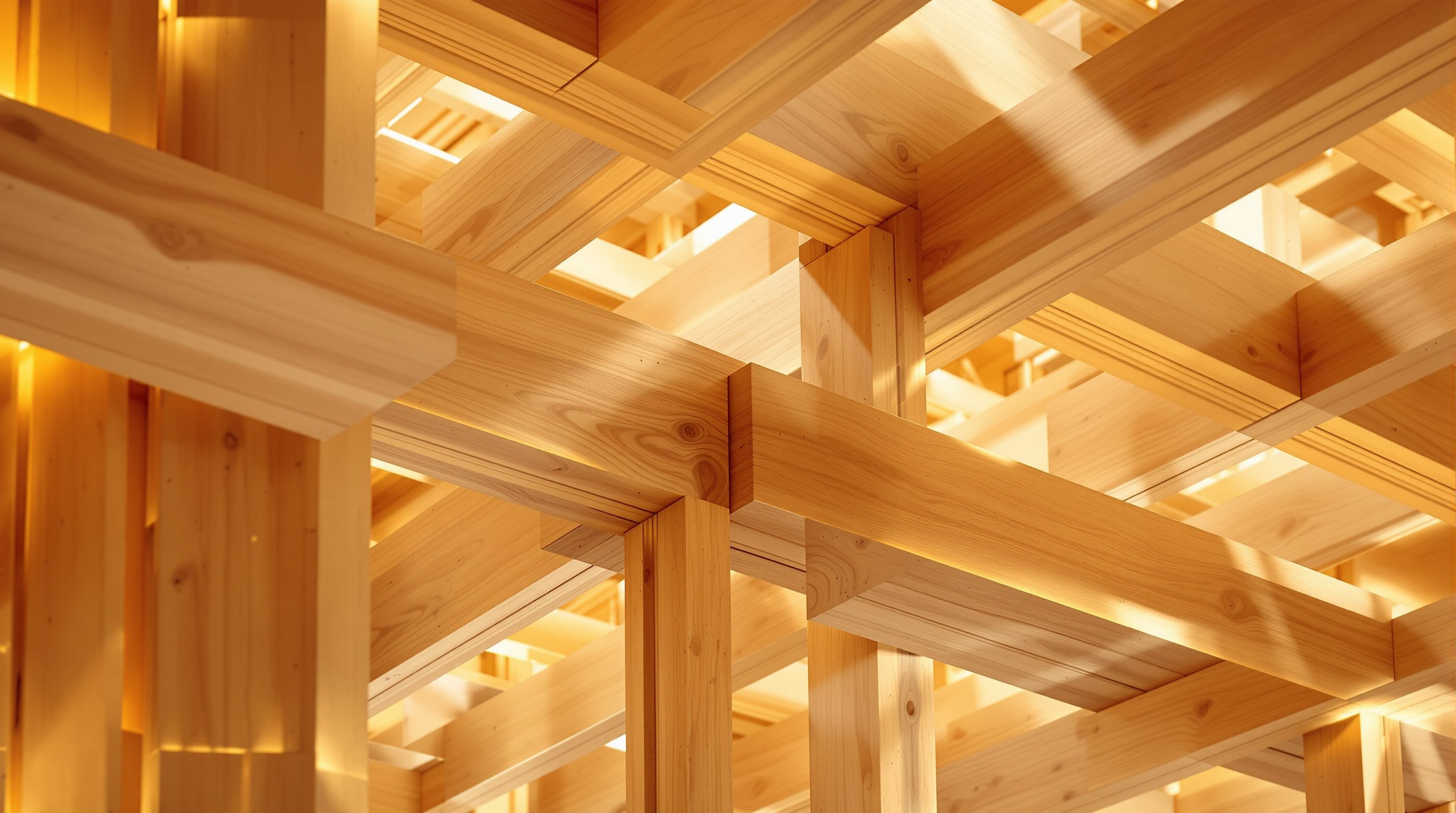
 Lesson 9.1
Lesson 9.1 · Detailing, Finishes & the Exposed Aesthetic
Connection Detailing
In a timber building the connections are where structure, buildability and beauty all meet at once - and deciding whether to hide the steel or celebrate it is one of the most architectural choices you will make
A mass-timber building is only as good as its joints. Everything - strength, speed, cost and character - passes through the connections.
In concrete you pour a frame that is monolithic - beams and columns become one continuous mass, and the connections almost disappear into the casting. Timber is the opposite. A mass-timber building is a kit of discrete, prefabricated pieces - panels, beams, columns - that must be joined together, and every load in the building has to travel through those joints to reach the ground. This makes connections the single most concentrated design problem in timber: they carry the structure, they decide how quickly and cheaply the building can be assembled, and, because timber is so often left exposed, they are frequently the thing you actually see.
That triple role - structural, buildable and visible - is what makes connection detailing the most architectural part of timber engineering, and the subject of this lesson. A joint can be a hidden steel plate slotted invisibly into the wood so the building reads as pure timber, or it can be a frankly expressed bracket, celebrated as a piece of tectonic honesty. Both are legitimate; the choice is yours to make and it changes the whole character of the building. What is never yours to invent is the capacity - how many fasteners, what steel, what spacing, what the joint can actually carry. That belongs to the structural engineer and the code. This lesson teaches you to design the joint as architecture while deferring its numbers to the specialist.
The joints ARE the design. Concealed or expressed - decide early. Survive: tolerance, movement, fire, moisture. You own intent; the engineer owns capacity.
Why connections are the heart of timber design
To design in timber well you have to reverse an instinct trained by concrete. A cast concrete frame is effectively continuous - the material flows around corners and the joints are formed in the pour, so a designer rarely thinks about them as discrete objects. Mass timber is a kit of parts: every column, beam and panel is a separate manufactured element, and the building only stands because those elements are fastened to one another. Every gravity load, every wind and seismic force, and every tie that holds the structure together as one has to pass through a connection. Get the connections right and the building is strong, quick to erect and elegant; get them wrong and it is weak, slow, expensive or ugly - often all four. This is why experienced timber engineers say the connections are the design.
Connections concentrate difficulty because timber is not steel. Wood is much stronger along the grain than across it, it is weaker in the small zones where fasteners bite, and it moves as its moisture changes - so a joint must introduce load into the wood gently, spread it across enough fibres, and tolerate a little movement without splitting. That is a real engineering problem, and it is precisely why the capacities are the engineer's province: how a connection actually performs depends on fastener type and spacing, edge and end distances, the direction of load to grain, the product, moisture and the governing code. None of those are numbers you should be inventing at the drawing board.
But a huge amount is genuinely yours. Where a connection occurs, how it is expressed, whether it is concealed or celebrated, how it coordinates with the grid, the services and the finishes, how it looks to someone standing under it - these are architectural decisions, and they must be made early, because a joint cannot be redesigned into a building after the grid and the products are fixed. The craft of timber detailing is to hold the two together: to compose beautiful, buildable joints as architecture, and to hand the structural engineer a clear, early brief so they can make those joints safe. Think of yourself as the author of the connection's intent and the engineer as the author of its capacity - and never confuse the two roles.
Concrete flows and hides its joints. Timber is a kit - every load passes through a connection. The joints ARE the design.
The connection families - and what each is good for
You do not need to design connections to speak about them intelligently, and a designer should know the broad families so they can brief an engineer and detail around the result. In mass timber the common approaches fall into a few groups. Dowel-type fasteners - screws, bolts, dowels and nails - are the workhorses: slender steel elements that pass through the timber and transfer load by bearing and shear. Long self-tapping screws in particular have transformed timber connections, letting a lot of capacity be introduced discreetly. Steel plates and brackets - flat plates, angle brackets, shoes and hangers, bolted or screwed to the timber - are the visible, adaptable family you see in many exposed frames. Concealed connectors are proprietary steel components routed into slots or pockets in the timber so that, once assembled, little or no steel shows. Traditional carpentry joints - mortise-and-tenon, dovetails and the like, sometimes revived with CNC precision - transfer load through shaped timber-on-timber bearing and are prized for their craft, though their capacity is limited and they are usually reserved for lighter or expressive work.
Each family trades off differently across the things you care about: capacity (how much it can carry), buildability (how quickly and forgivingly it goes together on site), appearance (how much steel shows), and cost. A screwed bracket is cheap, strong and fast but visible; a concealed connector is neat and clean but often more expensive and fussier to fit; a carpentry joint is beautiful but limited and slow. There is rarely a single right answer - only the right answer for this building, its loads, its budget and its intended look.
The practical point for a designer is to understand these families as a palette and to choose the intent early - "here we want the joints invisible," "here the bracket is part of the language" - then work with the engineer to realise it. The engineer will select the actual fasteners and their numbers to meet the loads and the code; you select the character and coordinate the detail. Knowing the palette lets you have that conversation as a partner rather than a spectator, and lets you draw a connection that is plausible from the first sketch rather than a wish that the engineer then has to reject.
Concealed or expressed - the most architectural choice
The single most consequential detailing decision in an exposed timber building is whether its connections are concealed or expressed, because it sets the entire visual language of the structure. In the concealed approach, the steel that does the work is hidden - plates slotted into routed grooves, screws driven at angles and plugged, connectors buried in pockets - so that what you see is timber meeting timber, apparently held by nothing. The building reads as pure, warm, monolithic wood; the effect can be serene and almost magical, a frame that seems to defy the need for fixings. In the expressed approach, the connectors are shown deliberately - a black steel bracket, visible bolts, a cast shoe - and made into a considered part of the architecture, in the honest tradition that a building should show how it stands up. Both are entirely valid; neither is more "correct."
The choice carries real consequences beyond looks. Concealed connections are often more expensive and more demanding to fabricate and fit, because the routing and the tolerances are exacting and there is less room to adjust on site; they can also complicate fire and inspection, since hidden steel may need protection and cannot be seen after assembly. Expressed connections are usually cheaper, faster and more forgiving, and they can be inspected at a glance - but only if the exposed steel is detailed with enough care to look intentional rather than industrial, and its own fire protection is resolved, because exposed steel softens in fire far faster than the charring timber around it. So the decision ripples into cost, programme, fire strategy and inspection, not just aesthetics.
Good practice is to decide the intent early and consistently, then let it guide a hierarchy: perhaps the primary frame's joints are quietly concealed while a few signature connections are expressed as moments of craft, or vice versa. What you should avoid is deciding by accident - discovering on site that connections meant to be invisible are studded with visible plates, or that "expressed" joints look like an afterthought. As the designer you own this intent; write it into the drawings and the engineer's brief, and coordinate it with the fire engineer, so the finished joints say exactly what you meant them to say.
Concealed = pure wood, no visible steel, pricier and fussier. Expressed = honest, cheaper, faster - but detail the steel with care and protect it in fire.
Detailing the joint - tolerance, movement, fire and craft
Whatever family and expression you choose, a connection has to survive four realities, and detailing well means designing for all of them. The first is tolerance and buildability. A timber building is prefabricated to fine tolerances but the world it lands in is not perfect, so joints need deliberate small gaps and adjustment - slotted holes, packing, a millimetre or two of play - or the kit simply will not go together on site. A connection that is theoretically strong but impossible to assemble has failed. The second is movement: wood shrinks and swells across the grain as its moisture changes, and a good detail lets that happen without splitting the timber or prising the joint apart - which usually means not restraining the wood hard across its grain and avoiding stacking many joints so their movement accumulates.
The third reality is fire, and it is safety-critical, so it is deferred to the fire engineer, but the designer must know it shapes the detail. Exposed timber chars slowly and predictably and can be engineered to keep its strength, but the steel in a connection does not char - it conducts heat and loses strength quickly - so connectors in a fire-rated exposed frame often need to be protected, recessed into the timber, or sized and covered so they survive the required time. This is a major reason concealed connections are sometimes chosen, and a major reason expressed steel must be checked by the fire engineer rather than assumed safe. The fourth reality is moisture and durability: a connection is a place where water can be trapped and steel can corrode, so details should shed water, avoid pockets that hold it, and keep the joint dry, especially anywhere near the envelope.
Holding all four together is the craft. And the discipline that makes it work is coordination: connections are designed in the BIM model with the engineer and the fabricator, because the fasteners, the routing and the tolerances all have to be manufactured into the pieces before they arrive - there is little cutting-and-fixing on a mass-timber site. So the designer's job is to set the intent, understand these four realities, and coordinate early and precisely with the engineer, the fire engineer and the fabricator, while deferring every capacity, fastener schedule and fire figure to them and the code. Design the joint as architecture; let the specialists make it stand up and survive.
Connection design (structural/timber engineer + code)
Fastener type and number, spacing, edge/end distances, capacity
Safety-critical and never a design-board number - every connection capacity comes from a licensed structural/timber engineer and the current code (NBC/IS; Eurocode 5 where used). Principles here only.
Fire protection of connections (fire engineer + code)
Protecting or recessing steel; fire performance of exposed connectors
Exposed steel loses strength fast in fire while timber chars slowly - connectors in a fire-rated frame must be resolved with the fire engineer and code, not assumed safe.
Tolerance & coordination
Assembly gaps, routing, fabrication in BIM
Joints are manufactured into the pieces off a coordinated model; deliberate tolerances make the kit assemble. Coordinate with engineer and fabricator - see Module 8.
Workshop — design the intent of one timber connection
Connection detailing begins with intent, long before any capacity is known. In this workshop you will take one connection in a simple timber frame and decide, as the designer, exactly what you want it to be - then write the brief that lets an engineer make it real.
A sketchbook and this lesson. No calculation - the point is to practise authoring a joint's intent and briefing the specialists who own its capacity.
Goal: a clear design intent for one connection and an engineer's brief
Inputs: a simple post-and-beam bay (real or sketched) + this lesson + a sketchbook
Time: ~45 minutes
- 1Pick one connection in a simple timber frame - say a beam-to-column joint in a post-and-beam bay - and sketch the two members meeting, roughly to proportion.
- 2Decide the expression: will this joint be concealed (steel hidden, pure timber reading) or expressed (a visible bracket or bolts as part of the architecture)? Write one sentence saying why, in terms of the character you want.
- 3Sketch the joint in your chosen expression, labelling what you think each part is doing - where the load comes in, how it passes into the column, where fasteners or a plate might sit - knowing you are showing intent, not sizing anything.
- 4List the four realities your detail must survive: assembly tolerance, timber movement across the grain, fire (protecting any exposed steel), and moisture. Note one thing your sketch does about each.
- 5Write a three-line brief to a structural and fire engineer: the intent (concealed/expressed), the look you must protect, and the questions you need them to answer - capacity, fasteners, and fire protection of any steel.
You’ll walk away with
One annotated connection sketch with a stated concealed-or-expressed intent, notes on how it handles tolerance, movement, fire and moisture, and a short brief to the engineers. It should read as a designer's intent that an engineer could then make safe - not as a pretend engineering calculation.
Three altitudes on the same idea
Read the band that fits you — or all three.
Connections are where your timber architecture is won or lost, so own them early. Decide the intent - concealed for a pure-timber reading, expressed for tectonic honesty, or a deliberate hierarchy of both - at concept, because joints cannot be inserted once the grid and products are fixed. Understand the connection families as a palette so you can brief and coordinate your structural engineer, and bring the fire engineer in on any exposed steel. Coordinate the detail in BIM with the fabricator so tolerances, routing and fasteners are built into the pieces. Own the character, the expression and the coordination; defer every capacity, fastener schedule, spacing and fire figure to the engineers and the code.
The joints of an exposed timber frame are among the most visible things in the room, so they are your business too. Whether a connection is invisible or a crafted black bracket sets the character of a timber interior as much as the wood itself. Learn to read the families and talk to the structural team about how joints will look, how steel is finished, and how your fit-out, linings and fixings meet the structure without compromising its expression or its fire protection. Where you fix into or against structural timber, coordinate with the engineer so you never quietly undermine a connection or its cover - the capacity and fire performance stay with the specialists.
Learning to see connections is how you start to think like a timber designer. Wherever you find an exposed timber building or photograph, look for the joints: are they hidden or shown? screwed brackets, slotted plates or carpentry? What does that choice do to the feel of the space? You are not expected to size a connection - that is engineering - but you are expected to understand that in timber the loads all pass through the joints, that concealed and expressed are both valid choices with real cost, buildability and fire consequences, and that a joint must tolerate assembly, movement, fire and moisture. Sketch connections you admire and label what each part might be doing.
“Timber connections are just carpentry - you nail or bolt the pieces together on site like a shed, and the joints are a minor practical detail once the structure is designed.”
Do it yourself
No tools needed - reason it through.
- 1Explain why connections are more central to design in timber than in cast concrete.
- 2Name the main connection families and say what each is good and less good for.
- 3Contrast concealed and expressed connections, including their cost, buildability and fire consequences - not just their looks.
- 4Why does exposed steel in a connection need special attention in a fire-rated timber frame?
- 5List the four realities a connection detail must survive, and which of them are the engineer's to make safe.
The one line to carry out
Peer-reviewed journals & authoritative standards
- 01Mass timber — Wikipedia — Mass timber, 2026.
- 02Woodworking joints — Wikipedia — Woodworking joints, 2026.
- 03Fastener — Wikipedia — Fastener, 2026.
- 04Glued laminated timber — Wikipedia — Glued laminated timber, 2026.
- 05Eurocode 5: Design of timber structures — Wikipedia — Eurocode 5: Design of timber structures, 2026.
Connections are where the timber structure becomes visible - and once we accept that the wood will be seen, we have to design the exposure itself. Next: the exposed timber aesthetic.
The author
Amogh N P
Architect, interior designer, and creative polymath. Studio Matrx began in his notebooks — his vision of design made honest, useful, and open to everyone. Its Academy is written and taught in his memory, and free, forever.
More about Amogh →