
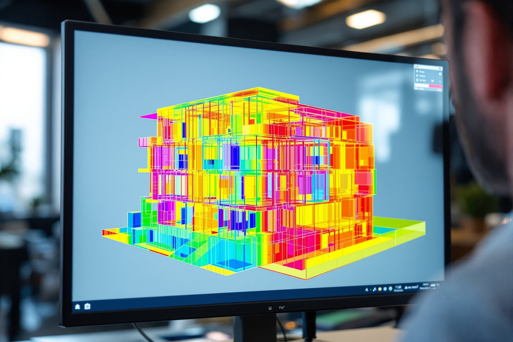
Performance simulation (energy, daylight, CFD)
Before a facade is built, its energy, light, airflow and stresses are predicted by software. The numbers are powerful — and dangerous, because a confident simulation of the wrong inputs looks exactly like the truth.
A simulation will give you a number to two decimal places. It will not tell you that the number is wrong.
Modern facade engineering runs on simulation. Before a panel exists, software predicts the building's annual energy use, the daylight on every desk through the year, the airflow up a double-skin cavity, the heat leaking through a bracket and the stress in a glass plate under wind. Used well, these tools turn the five conflicting jobs of the skin into numbers you can compare and optimise. Used badly, they are a trap: a simulation always produces a confident result, even when the inputs are nonsense, and a polished render of a wrong answer is the most expensive thing in facade engineering. The skill is not running the software — it is knowing what each tool actually models, where it lies, and how to check it against reality.
Five simulations, five questions — and one rule about trust
Energy modelling sizes the cooling load; climate-based daylight simulation predicts light over the whole year
Two simulations dominate facade performance. Energy modelling (EnergyPlus and its interfaces, or DesignBuilder/IES) predicts how the facade drives the building's annual heating and cooling — feeding in the U-value, SHGC, glazing ratio and shading to size the air-conditioning and check compliance with ECBC or Eco-Niwas Samhita. This is where the facade's thermal choices become a kWh and a rupee number.
Daylight simulation answers a different question: how much useful daylight reaches the space, and where is there glare? The serious tool is Radiance, a physically-based ray-tracer, usually run as climate-based daylight modelling (CBDM) — simulating real local sky conditions across a whole year to produce metrics like Useful Daylight Illuminance (UDI) and spatial Daylight Autonomy (sDA). This is a major advance on the old single-point daylight factor, which assumes one overcast sky and ignores orientation and the Indian sun entirely.
Both are the same five-jobs trade-off made quantitative: more glass lifts daylight but loads the cooling; shading cuts gain but can darken the space. Simulation lets you find the balance numerically instead of by argument.
Daylight factor asks 'how bright on one grey day?'. Climate-based modelling asks 'how good is the daylight, here, all year?'. For the Indian sun, only the second is honest.
CFD reveals airflow in cavities and rooms; THERM reveals the heat leaking through every thermal bridge
Two more simulations handle flows. CFD (Computational Fluid Dynamics) models air movement — the buoyancy-driven flow up a double-skin facade cavity (does the stack effect actually ventilate it, or does heat build up and cook the inner glass?), the cross-ventilation through openable facades, and wind pressure on the skin. For double-skin and naturally-ventilated facades, CFD is often the only way to predict whether the cavity behaves as intended.
Thermal simulation at the detail scale uses tools like THERM (2D finite-element heat transfer) to model thermal bridges — the heat that short-circuits through a metal bracket, a slab edge or a frame, bypassing the insulation. This produces the psi-value (linear thermal transmittance, W/m.K) that a whole-building U-value calculation needs but a 1D U-value misses. Ignore thermal bridges and your real envelope performance can be far worse than your spec claims — bridges can add 20-30% to heat flow on a poorly detailed facade.
These tools find what hand calculation cannot see: a stagnant cavity, a bracket bleeding heat, a corner running cold enough to condense. But they are also the easiest to get wrong, because the answer depends entirely on the boundary conditions you assume.
FEA predicts stress and deflection — and every simulation must be validated, or it is just a confident guess
The fifth simulation is structural. Finite Element Analysis (FEA) models how glass, frames and brackets stress and deflect under wind, dead and seismic load — predicting whether a glass plate stays within its allowable stress and the deflection limit (typically span/175 for curtain wall), and how brackets and connections behave. For complex geometry, cable-net walls or point-fixed glass, FEA is essential where the simple plate formulae of the codes run out.
Now the rule that governs every simulation in this lesson: a simulation is a model of reality, not reality, and an unvalidated model is a confident guess. The output always looks authoritative — smooth contours, numbers to two decimals — regardless of whether the inputs were sound. Validation means: sanity-checking against hand calculation and codes (does the FEA stress roughly match the IS 875-3 plate formula?), against test data (does the CFD cavity match a measured one?), and against physical reality (does the energy model's baseline match a similar real building's bills?). The peer-reviewed literature on double-skin facades is blunt that simulation results must be checked against measurement before they are trusted. The engineer who treats a simulation's output as truth, rather than as a hypothesis to verify, is the one who gets surprised on site.
Use simulation early and to compare, not to over-precise. At concept, a quick energy and daylight study comparing two or three glazing-and-shading options is worth more than a single hyper-detailed model late on — it shapes the design while it can still change. Insist on climate-based daylight modelling for the actual site, not a generic daylight factor, because the Indian sun and your orientation are exactly what a daylight factor ignores. And treat every simulation number as a comparison, not a guarantee: the value is in 'option A beats option B', far more than in the third decimal place of either.
You own the modelling and, more importantly, its validation. For each tool, know what it assumes: the boundary conditions in your CFD, the sky model in Radiance, the material and load inputs in your FEA, the schedules in your energy model. Always run a hand-calc sanity check alongside the simulation — an FEA stress that disagrees with the IS 875-3 plate formula by a factor of three means the model is wrong, not the formula. Model thermal bridges in THERM and feed the psi-values into the real U-value; a facade that ignores bridging can under-perform its spec by 20-30%. Document your assumptions so a reviewer can challenge them.
The simulations you never see are why the facade is detailed the way it is — the shading depth, the thermal break in the frame, the vented cavity, the glass thickness. When a detail seems fussy (a thermal break that complicates a bracket, a precise cavity gap), it is usually carrying a simulated requirement: break the thermal path and the bridge wakes up; close the cavity gap and the stack ventilation stops. On a tested mock-up, the measured performance is the real validation of all that simulation — which is why what gets built must match what was modelled.
ECBC 2017 / Eco-Niwas Samhita 2018 (India)
Energy-model compliance
Set the U-value, SHGC, VLT and RETV targets that energy modelling must demonstrate. ENS's RETV in particular is a simplified envelope metric for residential India — useful, but a single number that does not replace a full hourly energy model on complex buildings.
ASHRAE 90.1 + Appendix G
Energy modelling methodology (global)
The international reference for performance-based energy modelling and the baseline-building method. Widely used on Indian premium and green-rated projects, but its climate assumptions must be set to the actual Indian location, not a default.
IES LM-83 (sDA / ASE)
Climate-based daylight metrics
Defines spatial Daylight Autonomy and Annual Sunlight Exposure — the climate-based daylight metrics Radiance produces. A real-year, real-sky measure; far more honest than the single-sky daylight factor, but only as good as the local weather file used.
IS 875 (Part 3): 2015 (India)
Loads for structural FEA
The wind pressures any facade FEA must be checked against. FEA can model complex behaviour the code formulae cannot, but its results must reconcile with the code-derived design loads — the simulation does not override the code.
“The simulation gives a precise number, so the facade will perform exactly that way.”
A simulation predicts how a MODEL of the facade behaves under the ASSUMPTIONS you fed it — not how the real, imperfectly-built facade in the real, variable climate will behave. The output is always confident and precise-looking, even when the inputs are wrong; precision is not accuracy. Real performance depends on construction quality, occupant behaviour, weather and the gaps between model and reality. Simulations are powerful for comparing options and finding hidden problems, but every result is a hypothesis to validate against hand-calculation, test data and reality — never a guarantee.
Worked example — sanity-check a daylight simulation by hand
The discipline is never trusting a simulation you cannot roughly check. Here we estimate a daylight factor by hand as a sanity check on what a Radiance model should report — the back-of-envelope validation every engineer should run.
A calculator and the simplified average daylight factor formula. This is the HAND check you run against the software's answer.
Office room, given:

  Window glazed area     W   = 6.0 m2
  Glass visible transmittance  T = 0.60 (60%)
  Total room surface area  A = 120 m2 (walls+floor+ceiling)
  Average surface reflectance R = 0.5
  Visible sky angle      theta = 70 degrees

  Average daylight factor (simplified):
  DF = (T x W x theta) / (A x (1 - R^2))
  (theta in degrees; DF as a percentage)
- 1Numerator: T x W x theta = 0.60 x 6.0 x 70 = 252. This is the daylight 'supply' the window admits, weighted by visible sky.
- 2Denominator term (1 - R^2): with R = 0.5, R^2 = 0.25, so (1 - 0.25) = 0.75. Higher room reflectance (lighter finishes) shrinks this term and RAISES the daylight factor — bounced light matters.
- 3Denominator: A x (1 - R^2) = 120 x 0.75 = 90. The room's total surface area dilutes the daylight across everything it has to light.
- 4Average daylight factor: DF = 252 / 90 = 2.8%. A DF around 2% is the rough threshold for a daylit space, so 2.8% suggests this room is reasonably daylit on an overcast basis.
- 5The validation move: if your Radiance/CBDM model reported an average DF of 0.4% or 9% for this room, STOP — a 7-10x disagreement with the hand estimate means a model error (wrong glass transmittance, wrong geometry, wrong sky), not a discovery. The hand calc does not replace the simulation; it catches the simulation when it is wrong. (And note: DF assumes one overcast sky — the climate-based model is still needed for the real Indian sun and orientation.)
You’ll walk away with
A hand-calculated daylight factor used to sanity-check a daylight simulation — the validation habit that catches a wrong model before its confident, wrong number reaches the design.
One reflection on trusting numbers.
- 01Next time you see a facade performance claim (a daylight render, an energy figure), ask the two validation questions: what sky/weather/load did it assume, and was it checked against a hand calculation or a real building? If you cannot answer either, the number is a hypothesis, not a fact.
Five simulations answer the facade's five questions: energy modelling sizes the load, climate-based daylight modelling (Radiance) predicts real-year light, CFD reveals cavity and ventilation airflow, THERM exposes thermal bridges and their psi-values, and FEA predicts structural stress and deflection. Each is powerful and each is the same trap — a confident output regardless of input quality. The non-negotiable skill is validation: check every result against hand calculation, test data and reality before you trust it.
Energy modelling (EnergyPlus/IES) -> annual load and ECBC/ENS compliance. Radiance climate-based daylight modelling -> real-year UDI/sDA, far better than the single-sky daylight factor. CFD -> cavity and natural-ventilation airflow (essential for double-skin). THERM -> thermal bridges and psi-values (bridges add 20-30% heat flow). FEA -> stress/deflection (span/175), checked against IS 875-3. Every simulation is a model to validate, not reality.
What is the difference between daylight factor and climate-based daylight modelling?
Daylight factor is a single ratio of indoor to outdoor light under one standardised overcast sky — it ignores orientation, location and sun, which makes it poor for the Indian climate. Climate-based daylight modelling (CBDM), run in a tool like Radiance with a local weather file, simulates real sky and sun conditions across a whole year and produces metrics like Useful Daylight Illuminance and spatial Daylight Autonomy. CBDM is far more honest about how a facade actually performs for daylight.
Why does facade simulation need to be validated?
Because a simulation always produces a confident, precise-looking result — even when the inputs, boundary conditions or assumptions are wrong. Precision is not accuracy. Validation means checking the output against hand calculations and codes, against measured test data, and against the performance of similar real buildings. The peer-reviewed literature is clear that simulation results, especially for complex systems like double-skin facades, must be checked against measurement before they are trusted as design evidence.
What is a thermal bridge and why simulate it with THERM?
A thermal bridge is a path — a metal bracket, a slab edge, a frame — where heat short-circuits through the envelope, bypassing the insulation. A simple 1D U-value calculation misses it, but bridges can add 20-30% to a facade's real heat flow. THERM (and similar 2D finite-element tools) model the detail to produce a psi-value (linear thermal transmittance) that the whole-building U-value calculation needs, so the specified performance matches what the facade will actually deliver.
Peer-reviewed journals & authoritative standards
- 01Su, Z. et al. Multi-Disciplinary Characteristics of Double-Skin Facades for Computational Modeling Perspective and Practical Design Considerations. Buildings, 12(10):1576. — Buildings (MDPI), 2022.
- 02Multi-objective optimization of glazing and shading configurations for visual, thermal, and energy performance of cooling-dominant climatic regions of India. — (peer-reviewed; via ResearchGate), 2024.
- 03Review on Glass Curtain Walls under Different Dynamic Mechanical Loads: Regulations, Experimental Methods and Numerical Tools. IntechOpen. — IntechOpen, 2023.
- 04An approach to calculate the equivalent solar heat gain coefficient of glass windows with fixed and dynamic shading in tropical climates. Journal of Building Engineering. — Journal of Building Engineering (Elsevier), 2018.
Simulation, parametric geometry and the coordinated BIM model all generate one thing in the end: data. The final lesson follows that data off the design desk — into fabrication, into the drawings and schedules that build the facade, and into the digital twin that runs it for the next forty years.