
Mock-ups: VMU, PMU & testing
Before a single panel is mass-produced, a full slice of the real facade is built on a rig and attacked with wind, water and a pressure pump - because a leak found here costs a comment, and a leak found on the building costs a lawsuit.
They build one corner of your tower in a warehouse, hose it with a hurricane and suck the air out of it - and only if it survives do they make the other ten thousand square metres.
Somewhere in an industrial shed outside the city, a full two-storey slice of the facade stands bolted to a steel chamber. A fan can pressurise or depressurise it like a storm; rows of nozzles can throw wind-driven rain at it for hours; jacks can rack it sideways to fake an earthquake. This is the **performance mock-up**, and it is the most honest moment in the whole facade process. Renders lie, drawings idealise, but the mock-up tells the truth: does this skin actually keep the weather out under load? In a country where the monsoon arrives every year with horizontal rain, the answer matters enormously - and it is far cheaper to learn it on a rig than on the twentieth floor of a finished building.
Two mock-ups, two questions: does it look right, and does it perform?
The visual mock-up proves appearance; the performance mock-up proves it survives the weather
Two different mock-ups answer two different questions, and confusing them is a classic error.
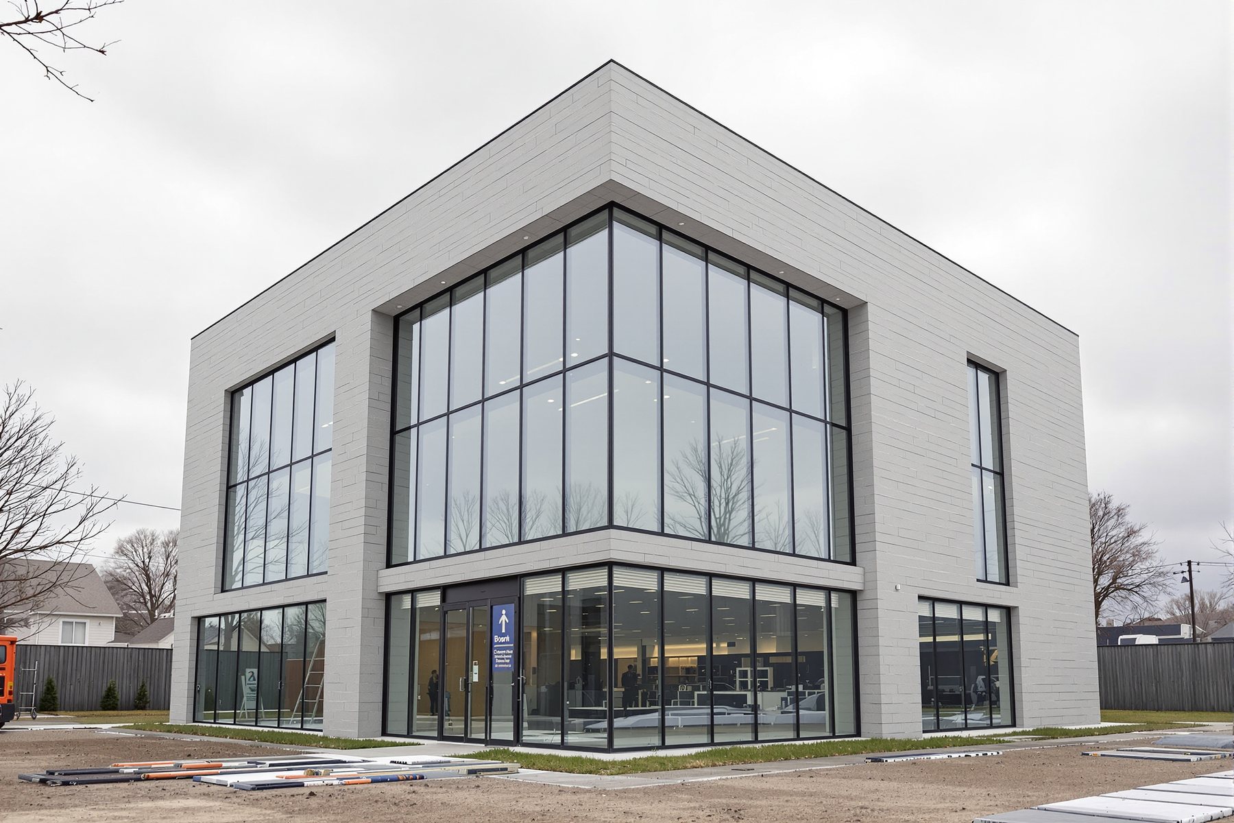
The visual mock-up (VMU) is about appearance - usually built on or near the site, sometimes on the building itself, it confirms colour, finish, glass tint, sightlines, joint shadows and the look of the real materials at full size and in real daylight. It is the architect's last cheap chance to adjust the look. The VMU is not tested for performance.
The performance mock-up (PMU) is about performance - a full, representative section of the real facade (typically two storeys, including a horizontal and vertical joint, an opening, and a corner or interface) built on a sealed test chamber at an accredited lab or rig. It is subjected to a defined test sequence - air, water, structural, movement, sometimes seismic and impact - to prove the facade meets its performance spec before mass fabrication. Find a water path on the PMU and it's a controlled, cheap lesson; find it on the building and it's a leak dispute. The PMU is the facade industry's single most valuable risk-reduction ritual.
VMU = does it LOOK right (no test). PMU = does it PERFORM (the full test sequence). Both exist; only the PMU goes on the rig.
Air, then static water, then dynamic water, then structural, then movement - in that order, for a reason
The PMU is run through a defined sequence, and the order is deliberate - benign tests first, destructive tests last, with repeats to expose damage.
A typical CWCT/ASTM sequence runs: air infiltration and exfiltration (ASTM E283 - measure air leakage at a test pressure, e.g. 300 Pa); static water penetration (ASTM E331 - a uniform pressure across a calibrated water spray, hold for a set time, no water past the design line); dynamic water penetration (AAMA 501.1 - an aircraft-engine or fan generates wind-driven rain, simulating the gusty reality static tests miss); structural performance (ASTM E330 - apply the design positive and negative wind pressure and measure deflection and permanent set); inter-storey movement / seismic racking (rack the rig to the design drift and re-test water); and on impact-rated facades, a soft- and hard-body impact test.
The sting in the tail: after the structural and movement tests, the air and water tests are repeated. A facade that passed water dry, then leaked after being flexed to design wind and racked for drift, has failed - because that is what the real building will experience. The sequence is designed to catch the joint that only opens under load.
The numbers come from the design wind load - and the test pressure is a fraction of it
The test pressures are not arbitrary - they are derived from the building's design wind load, which itself comes from IS 875 (Part 3) in India or the equivalent code abroad. The convention (CWCT and common practice) is roughly: air and static water are tested at a serviceability fraction of the peak design wind pressure (water test pressure is often a percentage of the design wind pressure, with a typical floor and ceiling - e.g. not less than 600 Pa and not more than ~700 Pa for many projects, but always per the project spec); the structural test applies the full design wind pressure (and often 1.5x or a proof factor for the safety/ultimate test); and dynamic water uses a wind generator producing a defined pressure pulse.
The pass criteria are crisp: no uncontrolled water penetration past the designed drainage line during the water tests; air leakage below the spec limit (e.g. <= 1.5 m3/hr.m2 at 300 Pa); deflection within span/175 (or the project limit) and permanent set below a small percentage of the deflection after the structural test; and the repeat water test must still pass after structural and movement loading. A PMU that passes is the benchmark every installed panel is then measured against.
Use the VMU as a design tool, not a contractual box to tick. Standing in front of a full-size visual mock-up in real daylight is the truest preview of your building you will ever get before it exists - it is the last cheap moment to adjust a glass tint, a joint shadow or a finish. Attend the PMU too: watching your facade get hosed and pressurised on the rig builds an instinct for why the engineer fusses over weeps and gaskets. And never let the mock-up programme get squeezed - a skipped or rushed mock-up is exactly how a building ends up leaking on handover.
You write the test specification and you witness the tests. Be ruthless about what the PMU must demonstrate - specify the sequence (E283, E331, E330, AAMA 501.1, racking) and the exact pass criteria (test pressures, leakage limits, span/175, the repeat water test after structural). Insist the PMU is representative: include the worst joint, a corner, an opening and a real interface, not an easy flat panel. Witness it personally; a failure on the rig is a gift, and the temptation to 'tweak and re-test quietly' is how an unresolved weakness ships. Derive the test pressures from the IS 875-3 design wind, not a round number someone remembered.
The mock-up is the **right answer** - the proven, signed-off benchmark that every installed panel is checked against. Learn what the PMU was tested to (the test pressures, the leakage limit, the deflection limit) because those become your acceptance criteria on the scaffold. On site, field water-spray tests (AAMA 501.2) on the installed facade re-prove on the real building what the PMU proved on the rig. If the installed detail differs from the tested mock-up, that is a red flag worth raising - the building only inherits the mock-up's performance if it is built the same way the mock-up was.
ASTM E283 / E330 / E331
Air, structural & static water lab tests
The classic North-American trio - air leakage (E283), structural under uniform wind load (E330), water penetration under static pressure (E331). Precise and widely specified, but lab tests on a representative sample, not a guarantee for every junction on the building.
AAMA 501 series
Curtain-wall dynamic & field testing
AAMA 501.1 (dynamic water with a wind generator), 501.2 (field water-spray check of installed facades), 501.4/501.7 (inter-storey/seismic movement). Dynamic water catches gusty wind-driven rain that the static test can miss - important for monsoon conditions.
CWCT Standard & IS 875 (Part 3): 2015
Test sequence + design wind source
CWCT defines the test sequence and pass criteria most premium specs follow; IS 875 (Part 3) gives the Indian design wind pressure the test pressures are derived from. CWCT is a benchmark, not Indian law - the project spec must localise the numbers.
“If the facade passed the water test once, it is proven watertight - the rest of the sequence is a formality.”
Passing the static water test dry proves nothing about how the facade behaves under load. The whole point of the sequence is that the structural and movement tests come AFTER the first water tests, and then the water tests are repeated. A joint can be perfectly watertight at rest and open up under design wind deflection or inter-storey racking - and that is exactly the condition the real building faces in a monsoon storm. A mock-up only proves watertightness if it stays watertight after being flexed to its design loads.
Worked example - derive the PMU test pressures from the design wind
The test pressures on a PMU are not invented - they are calculated from the building's design wind load. Let's derive the water and structural test pressures for a curtain wall on a tall office, the way a facade engineer writes them into the test spec.
The building's design wind pressure (from the structural engineer's IS 875-3 analysis), a calculator, and the convention that links test pressure to design wind pressure.
GIVEN (from IS 875-3 analysis of a tall office):

  Design (peak) wind pressure, p_design = 2.0 kPa = 2000 Pa
  Convention (per project spec, CWCT-style):
    Air test pressure        = 300 Pa (fixed serviceability)
    Static water test         = 25% of peak design wind
                                (floor 600 Pa, ceiling 700 Pa)
    Structural serviceability = 1.0 x peak design wind
    Structural safety/proof   = 1.5 x peak design wind
Deflection limit = span/175, mullion span L = 3500 mm- 1Air test pressure. This is a fixed serviceability value from the spec - 300 Pa. The PMU must leak no more than the spec limit (say <= 1.5 m3/hr.m2) at this pressure. No calculation needed, but record it.
- 2Static water test pressure. Take 25% of the peak design wind: 0.25 x 2000 Pa = 500 Pa. But the spec sets a floor of 600 Pa - so the calculated 500 Pa is overridden, and the static water test is run at 600 Pa (the floor governs because 500 < 600). Lesson: always check the calculated value against the spec floor and ceiling.
- 3Dynamic water test. The dynamic test (AAMA 501.1) is run at the same pressure as the static water test - 600 Pa here - but with a wind generator producing the gusty, fluctuating flow that simulates wind-driven rain. The pass criterion is identical: no uncontrolled water past the drainage line.
- 4Structural serviceability test. Apply the full peak design wind, positive and negative: +2000 Pa and -2000 Pa. Measure the mullion deflection. The limit is span/175 = 3500 / 175 = 20 mm. If the measured deflection exceeds 20 mm, the facade fails serviceability even if nothing breaks - too much deflection cracks glass and breaks seals.
- 5Structural safety/proof test. Apply 1.5x the peak design wind: 1.5 x 2000 = 3000 Pa, positive and negative. After unloading, the permanent set must be small (commonly < span/500 or a spec percentage) - the facade may deflect under this proof load but must spring back, with no glass breakage, no disengagement and no permanent distortion.
- 6Repeat the water test. After the structural and any movement/racking tests, re-run the static water test at 600 Pa. If the facade now leaks where it was dry before, it has FAILED - the structural loading opened a joint. This repeat is the whole reason the sequence is ordered the way it is.
You’ll walk away with
A complete PMU test-pressure schedule - air 300 Pa, static and dynamic water 600 Pa (floor governs over the calculated 500 Pa), structural serviceability +/- 2000 Pa with a 20 mm deflection limit, proof +/- 3000 Pa, and a repeat water test at 600 Pa - all derived from a 2.0 kPa design wind. The exact numbers a facade engineer writes into the test specification.
Two ways to internalise the test sequence.
- 01Find a video or photo of a curtain-wall performance mock-up under test (the test chambers and water nozzles are distinctive). Identify which test you're seeing - is it the static water spray, the dynamic wind-generator test, or the structural pressure test?
- 02Take a design wind pressure of 1.6 kPa and a span of 4000 mm and repeat the worked example: what are your air, water (check the 600 Pa floor), serviceability and proof test pressures, and your span/175 deflection limit?
A facade is proven before it is mass-produced: the visual mock-up proves appearance, and the performance mock-up proves the skin survives a defined sequence of air, static and dynamic water, structural and movement tests - with the water tests repeated after the facade has been flexed to its design loads. The test pressures are derived from the IS 875-3 design wind, and the passed PMU becomes the benchmark every installed panel must match.
VMU proves appearance (no test); PMU proves performance on a rig. Sequence: air (E283), static water (E331), dynamic water (AAMA 501.1), structural (E330) at design and proof wind, movement/seismic racking - then repeat air and water. Test pressures come from the IS 875-3 design wind (air ~300 Pa, water a fraction of design wind with a floor, structural at 1.0x and 1.5x). Pass = no uncontrolled water, leakage below limit, deflection within span/175, small permanent set, and a clean repeat water test.
What is the difference between a VMU and a PMU?
A visual mock-up (VMU) proves appearance - colour, finish, glass tint, sightlines and joints - usually built on or near the site at full size, and is not performance-tested. A performance mock-up (PMU) proves performance - a full representative section of the facade is built on a sealed test chamber and subjected to a defined sequence of air, static and dynamic water, structural and movement tests to confirm it meets the performance spec before mass fabrication. The VMU answers 'does it look right?'; the PMU answers 'does it perform?'.
What is the order of facade mock-up tests, and why does the sequence matter?
A typical sequence is air leakage (ASTM E283), static water penetration (ASTM E331), dynamic water (AAMA 501.1), structural under design and proof wind (ASTM E330), and inter-storey movement or seismic racking - then the air and water tests are repeated. The order matters because the structural and movement tests come before the repeat water test: a joint can be watertight at rest but open under wind deflection or building drift, and the repeat test is designed to catch exactly that failure - the condition the real building faces in a storm.
How are facade test pressures decided?
They are derived from the building's design wind pressure, which comes from IS 875 (Part 3) in India. By convention the air test runs at a fixed serviceability pressure (often 300 Pa), the water tests at a fraction of the design wind pressure (with a project floor and ceiling, commonly around 600 Pa), the structural serviceability test at the full design wind pressure, and the proof test at about 1.5 times it. Deflection must stay within the project limit (often span/175) with only small permanent set after the proof load.
Peer-reviewed journals & authoritative standards
- 01Bedon, C. et al. Performance of structural glass facades under extreme loads - design methods, existing research, current issues and trends. Construction and Building Materials, 163. — Construction and Building Materials (Elsevier), 2018.
- 02Review on Glass Curtain Walls under Different Dynamic Mechanical Loads: Regulations, Experimental Methods and Numerical Tools. IntechOpen. — IntechOpen (peer-reviewed chapter), 2023.
- 03Material Selection and Characterization for a Novel Frame-Integrated Curtain Wall. (PMC8069006). — Materials / NCBI-PMC, 2021.
A passed mock-up proves the design - but the design only reaches a rig because the right contractor was chosen to build it. How you specify, tender and assess that contractor, and the supply chain and warranties behind them, is next.