

Paraline & Perspective
Two ways to fold three dimensions onto one sheet — the measured honesty of paraline and the seen truth of perspective.
A plan and a section describe a building truly, but no one has ever seen a building that way. To show a form in the round — three faces at once, in one picture — we use two pictorial systems. Paraline drawings keep parallel lines parallel and let you scale measurements straight off the sheet; they are the designer's thinking tool. Perspective drawings let parallels converge and distant things shrink, exactly as the eye sees; they are how a space is finally felt. This unit teaches the geometry behind both.
Learning objectives
By the end of this lesson, you will be able to — mapped to the course outcomes for Architectural Graphics II:
By the end you can construct an isometric, plan oblique or elevation oblique drawing, choosing the paraline system that best shows the face or planes you most want to keep true.
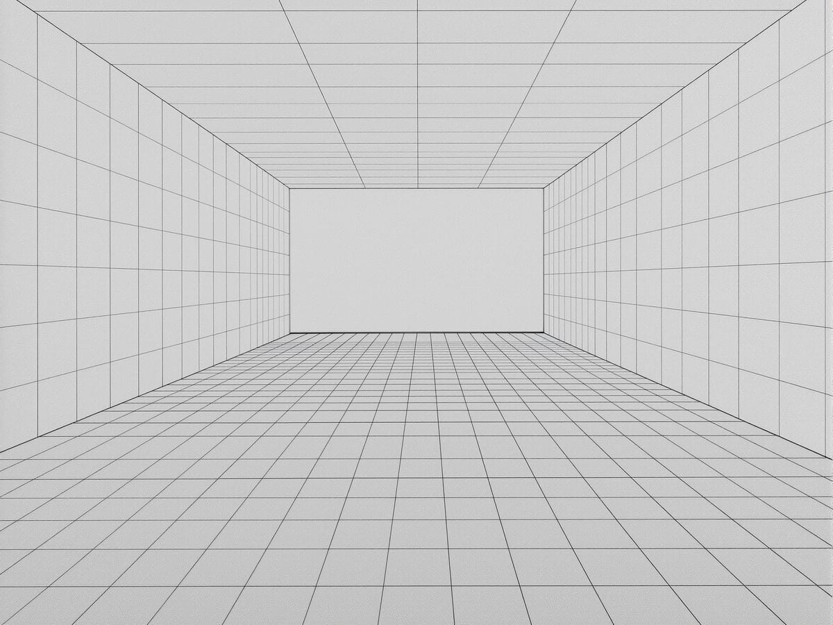
By the end you can set up a one-point perspective with the diagonal-point method and a two-point perspective with the measuring-point method, locating SP, PP, HL and the vanishing points correctly.
By the end you can predict how moving the station point up, down, nearer or farther changes the horizon, the spread of the vanishing points and the sense of depth in a view.
By the end you can judge whether a paraline or a perspective view — and which variety of each — communicates a given design idea most honestly and without distortion.
The big ideas
Paraline drawing is the friendly middle ground between the flat plan and the demanding perspective: a single aerial or worm's-eye view in which edges that are parallel on the building stay parallel on the paper, so true lengths can be measured along the axes.[1, 5]
One picture, parallel lines kept parallel
A paraline drawing folds plan, elevation and section into a single pictorial image, yet it stays measured. Two rules hold across the whole family: every set of parallel lines in the object stays parallel in the drawing, and every line running along one of the three principal axes can be drawn to true scale. That is why paraline sits between the multiview drawings and perspective — it borrows the pictorial reading of one and the measurability of the other. The trade is viewpoint: a paraline is always looking down from above or up from below, never at eye level, so it shows what we know an object to be rather than how a single eye would see it.[1, 2]
In practice
Now the converging world. Fix a station point and a picture plane, and build a perspective step by step — one-point by the diagonal-point method, two-point by the measuring-point method — plus the paraline's gift for exploded, cutaway and phantom views.[1, 2]
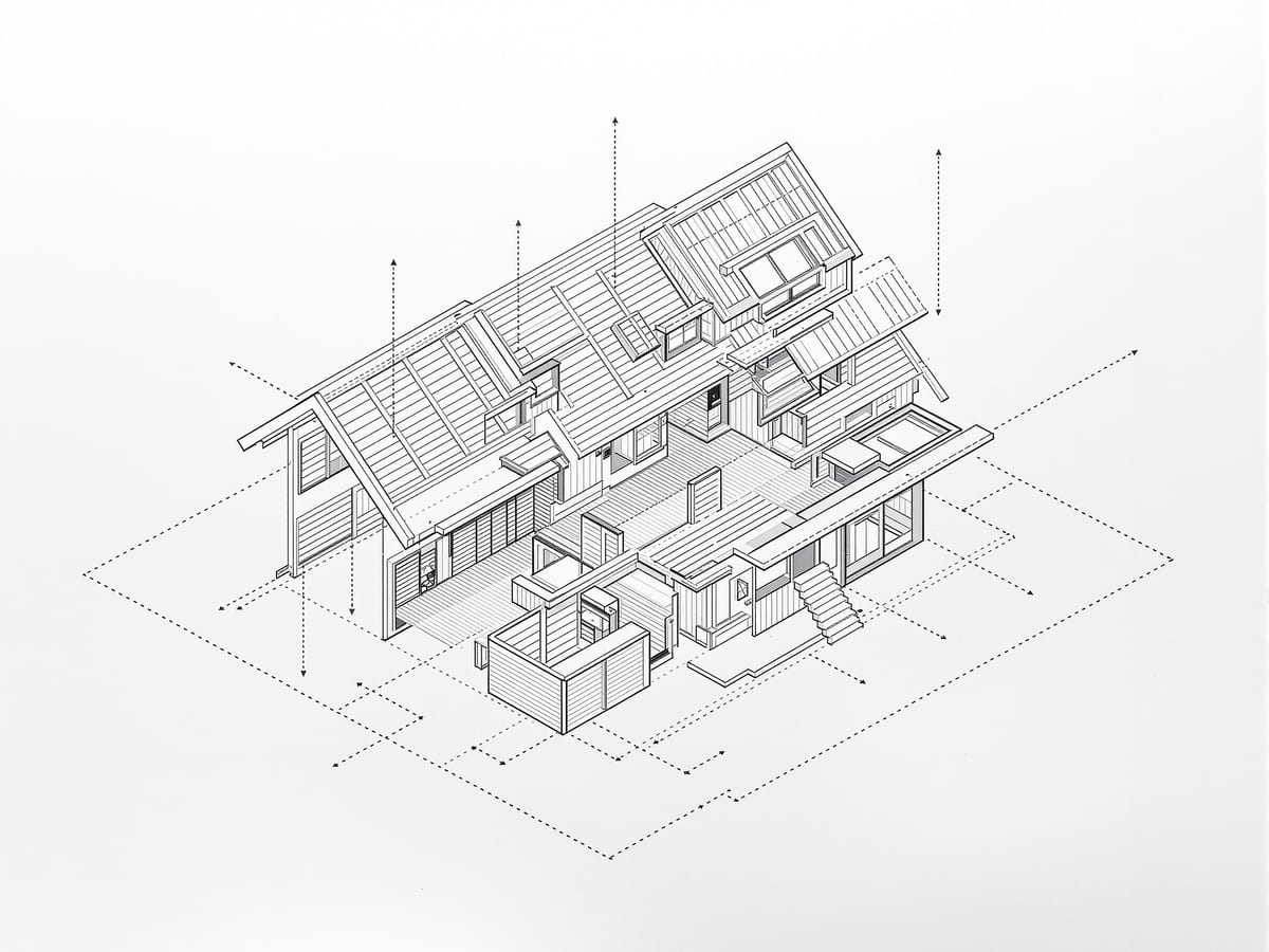
Opening a paraline to show the inside
A paraline need not stop at the outer shell. In an expanded (or exploded) view you slide the parts apart along the axes, freezing the object mid-explosion at the instant its assembly reads most clearly — ideal for layered construction details or the stacking of storeys. A cutaway removes an outer layer, or follows a three-dimensional route through the form, to reveal the space or structure within; articulate the cut edge with a heavier line or a tone so the plane of the cut is unmistakable. A phantom view instead makes selected parts transparent, so the whole envelope and its hidden interior are seen at once. A sequence of paraline frames can even narrate a process unfolding in time.[1, 4]
Paraline vs perspective
| Aspect | One | The other |
|---|---|---|
| How it treats parallels | Parallel lines stay parallel throughout | Parallel lines converge to vanishing points |
| Measurability | Axial lines drawn to true scale, directly measurable | Sizes diminish with depth; depth needs construction to measure |
| Viewpoint | Always aerial (above) or worm's-eye (below), never eye level | Set at any chosen eye level on the horizon |
| What it represents | What we know — an objective reality | What a single eye sees — an optical reality |
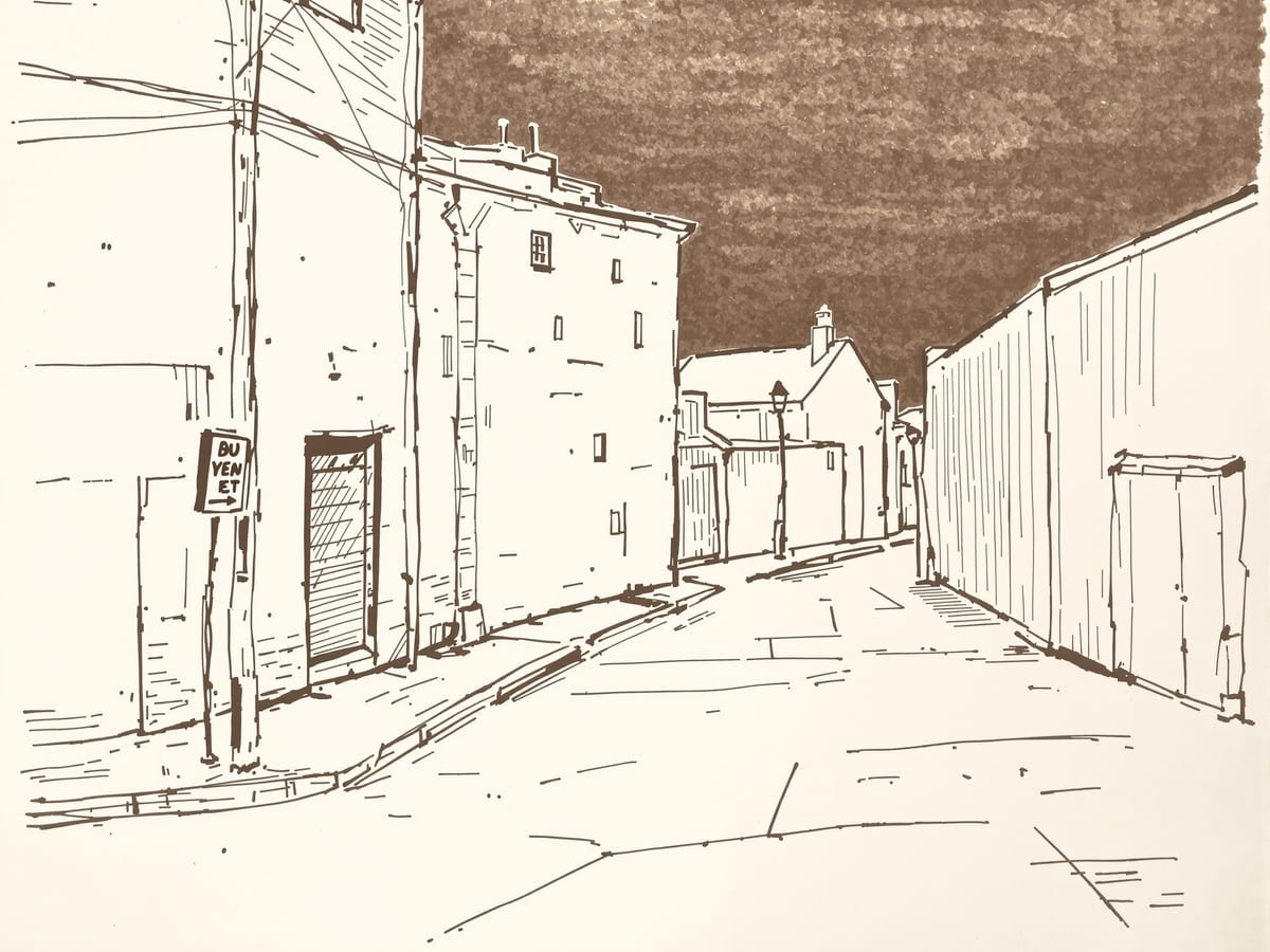
| Best used for | Early ideas, assemblies, cutaways and exploded views | Experiential interior and exterior scenes at human scale |
Key terms
A single-view pictorial drawing in which parallel lines stay parallel and axial lines are drawn to true scale, seen from above or below.
A paraline in which the three axes lie 120 degrees apart (two at 30 degrees to horizontal), giving all three faces equal, undistorted emphasis.
A paraline built on the true plan, keeping horizontal planes true in size and shape at a high angle of view.
A paraline that keeps one vertical face parallel to the picture plane and therefore true, with depth running back at an angle.
The fixed position of the observer's single eye from which a perspective is projected.
The horizontal reference line at the observer's eye level on which all horizontal vanishing points lie.
The point at which a set of parallel lines appears to converge as it recedes into the depth of a perspective.
A special vanishing point used to carry true dimensions from a measuring line onto a line receding in perspective.
Studio task
Take a simple massing — two or three stacked boxes. First draw it as an isometric, measuring every edge along the axes so the drawing is fully scaleable. Then draw the same massing as a one-point interior perspective, fixing a horizon at eye height and letting the depth lines run to a single vanishing point. Notice which drawing you would hand a builder, and which you would hand a client.
Self-assessment
1. When you draw an isometric with one axis vertical, at what angle to the horizontal do the other two axes fall?
2. Which paraline drawing keeps the horizontal planes of the object true in size and shape?
3. In a perspective, moving the picture plane closer to or farther from the station point changes what?
Recap
References & further reading
- [1]Francis D.K. Ching, Architectural Graphics (6th ed.). Hoboken: John Wiley & Sons, 2015.
- [2]Francis D.K. Ching, Design Drawing (2nd ed.). Hoboken: John Wiley & Sons, 2010.
- [3]Francis D.K. Ching, Architecture: Form, Space, and Order (4th ed.). Hoboken: John Wiley & Sons, 2014.
- [4]Rendow Yee, Architectural Drawing: A Visual Compendium of Types and Methods (4th ed.). Hoboken: John Wiley & Sons, 2012.
- [5]Robert W. Gill, Basic Perspective. London: Thames & Hudson, 1974.
- [6]Robert W. Gill, Manual of Rendering with Pen and Ink. London: Thames & Hudson, 1984.
Further reading
- Ernest Ralph Norling, Perspective Made Easy. New York: Dover Publications, 1999.
Sources gathered and fact-checked June 2026. Published values vary by source, sample and method — treat as indicative and confirm against the cited standard before structural use.
Where this course goes next
A perspective drawn in outline is only half a drawing. The next unit gives it depth and life — tone, light, shade and shadow, and the people, furniture and landscape that set the scale and make a drawing feel inhabited.
The author
Amogh N P
Architect, interior designer, and creative polymath. Studio Matrx began in his notebooks — his vision of design made honest, useful, and open to everyone. Its Academy is written and taught in his memory, and free, forever.
More about Amogh →