
 Lesson 3.1
Lesson 3.1 · Timber Structural Systems
Post-and-Beam Timber Frames
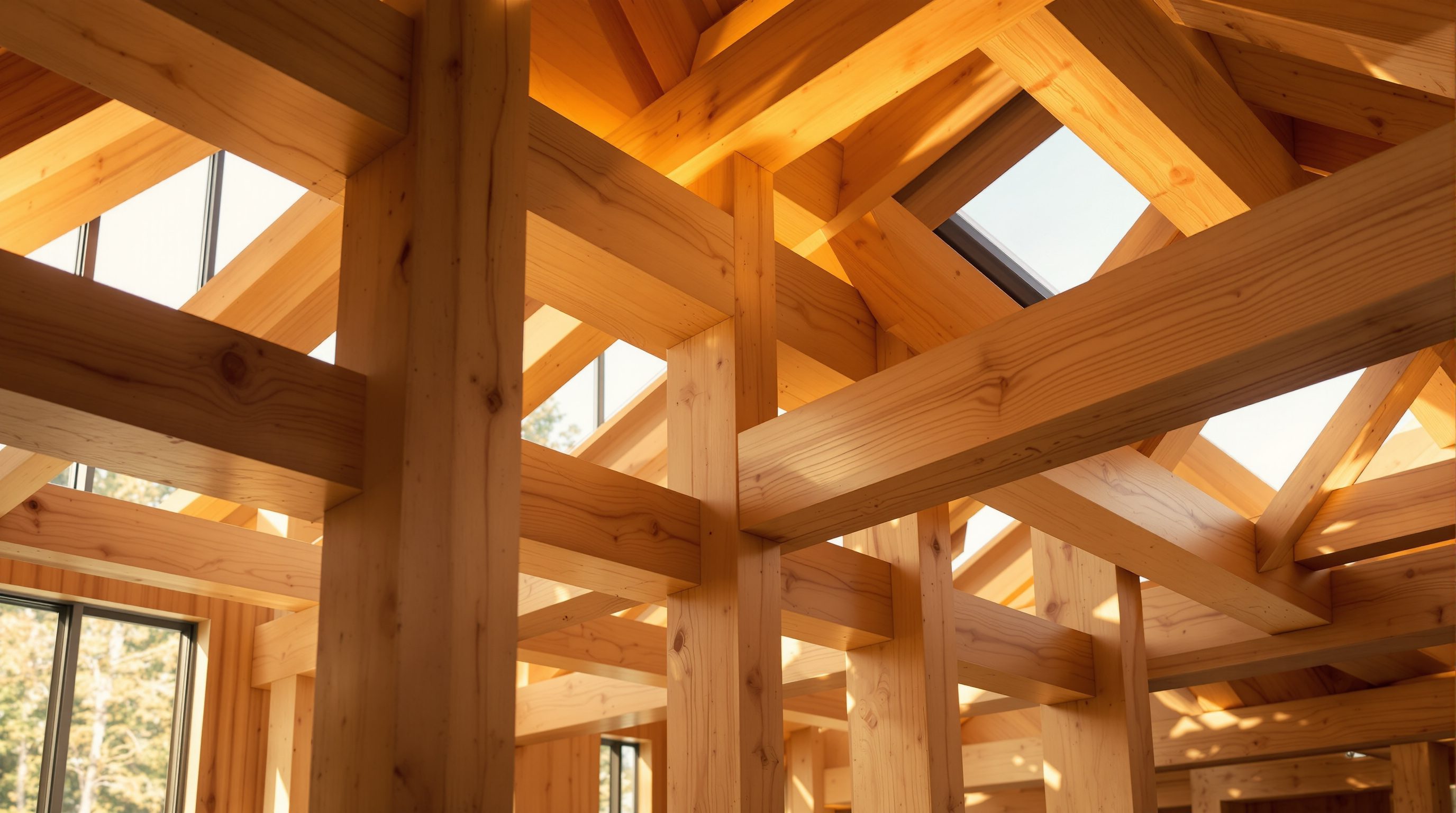
The classic mass-timber structure is a clean skeleton of glulam columns and beams that carries everything and frees the walls, giving the open, flexible, light-filled spaces timber does so beautifully
Take away the load-bearing walls, stand up a few big timber posts and beams, and the whole plan opens up.
Picture the oldest and most intuitive way to build with wood: stand up posts, lay beams across them, and rest a floor or roof on top. Timber framing has done exactly this for millennia, in barns, temples and houses across the world. The post-and-beam idea is beautifully simple - a skeleton of vertical columns and horizontal beams carries all the weight down to the ground, and the walls, freed of any structural job, become whatever you want them to be: glass, light infill, or nothing at all.
Mass timber takes that ancient logic and supercharges it. Swap sawn posts and beams for engineered glulam columns and beams, and you can span further, carry more, and build taller with slender, reliable members made to precise sizes in a factory. The result is the classic mass-timber structure: an elegant timber skeleton that opens up the plan and puts the warmth of wood on display. This lesson teaches how that frame actually works - how load travels through it, how the floor spans between beams, and, honestly, what it does not do on its own.
Skeleton carries, walls freed. Deck to beam to column to ground. It won't brace itself - give it bracing, a core or moment joints.
The skeleton idea: separate carrying from enclosing
The single most important idea in a post-and-beam frame is a separation of jobs. In a load-bearing masonry building, the walls do two things at once - they hold the building up and they enclose the space - which is why such buildings tend to have thick walls, small openings and rigid plans. A frame splits those jobs apart. A discrete skeleton of columns and beams takes on the whole structural task of carrying gravity to the ground, and that liberates the walls entirely: since they no longer hold anything up, they can be thin, movable, glazed from floor to ceiling, or simply left out. This is the same principle that let early modernism open its facades to glass, and in timber it feels especially generous because the structure itself is beautiful.
Think of it as a grid of strong points rather than continuous walls. Columns stand at the intersections of a structural grid; beams run between the columns to catch the floors and roof; the floor or roof deck spans across the beams to make the usable plane. Load is gathered by the deck, handed to the beams, handed to the columns, and delivered to the foundations - a clean chain of hand-offs we will trace in a moment. Because the load is concentrated into a small number of members, those members have to be strong, which is exactly what engineered timber makes possible without them becoming clumsy.
The design consequence is freedom. An open, column-dotted plan can be subdivided any way you like with non-structural partitions, reconfigured years later without touching the structure, and wrapped in as much glass as the climate allows. For offices, studios, markets, libraries, workshops and homes that want flexibility and daylight, the frame is a natural fit. And because the columns and beams are on show, the structure becomes the architecture - the rhythm of the grid, the meeting of post and beam, the grain of the wood all read as the character of the room. That expressive, flexible openness is the first reason the post-and-beam frame is the classic mass-timber move.
Posts + beams do the carrying. Walls stop being structural - so they can be glass, light, or nothing. That's the freedom.
Glulam: the engineered post and the engineered beam
What makes the modern timber frame different from the old barn is the member itself. The workhorse of the mass-timber frame is glulam - glued laminated timber - in which many kiln-dried boards are bonded face to face under pressure into a single large, straight (or curved) beam or column. That simple move solves the historic problems of sawn timber all at once. A glulam member can be far longer and deeper than any log, so it spans halls and open floors a solid piece never could. It is dimensionally stable and predictable, because the boards are dried, graded and the natural defects dispersed and averaged out across the section rather than concentrated in one weak knot. And it can be made to precise, repeatable sizes, so the frame arrives as a set of engineered components rather than variable natural pieces.
In a frame, glulam plays two distinct roles. As a beam, it works in bending - it has to resist sagging under the floor load, so it is made deep in the direction of the span, its depth doing the heavy lifting. As a column, it works mainly in compression - it has to carry the stacked weight straight down without buckling, so its job is to be stiff and well-proportioned for its height. The same material, oriented and sized for the task, does both. Alongside glulam you will meet LVL and other engineered members playing similar structural roles, and in many frames the floor plane is made of CLT panels - but the beams and columns are most often glulam, and the mental model of "engineered posts and engineered beams" holds.
A word of discipline belongs here. The exact size of every beam and column - how deep, how wide, what grade, spanning how far - is a structural-engineering result, not something you eyeball from a rule of thumb. Spans, loads, deflection and vibration limits, and the buckling of slender columns all feed into it, and it is the timber engineer's calculation to code. What you own as the designer is the concept: the grid, the spans you are asking for, the ambition for openness and slenderness - and then you brief the engineer, who turns that into real members. Any dimension quoted in this course is illustrative of the idea, never a value to build from.
The deck, the load path, and where load goes
A frame of posts and beams is not a building until something spans between the beams to make a floor or roof you can stand on - the deck. In mass timber the deck is usually a solid engineered plane: CLT panels, nail-laminated or dowel-laminated timber, or a timber-concrete composite, laid across the beams. The deck does two things at once. It carries the floor loads across the gap between beams (spanning the short way, beam to beam), and, tied down properly, it also acts as a diaphragm - a stiff horizontal plate that ties the whole floor together and shares out sideways forces, a role that matters enormously once we start thinking about stability.
With the deck in place we can trace the full gravity load path, and understanding it is the heart of reading any structure. Weight - people, furniture, finishes, the deck's own mass - lands on the floor deck. The deck carries that load sideways to the beams it rests on. Each beam gathers the load from the deck on either side and carries it along its span to the columns at its ends. Each column collects the load from the beams meeting it, adds the weight of everything stacked above, and carries the accumulated total straight down. At the bottom, the foundation spreads that concentrated load safely into the ground. It is a chain of hand-offs, and it explains why columns get more heavily loaded lower down a tall frame (they are carrying more storeys above) and why the connections where members meet are so critical - every hand-off happens at a joint.
Those joints deserve respect. Unlike concrete, which is poured monolithic, a timber frame is assembled from discrete pieces, so the connections between beam and column, column and column, and deck and beam are where the structure is made continuous - and where much of the engineering effort and cost sits. Connections are typically steel: plates, brackets, dowels, screws and bolts, concealed or expressed, designed to transfer the calculated forces and to behave predictably in fire. We meet connections properly in Module 4; here the point is simply that a frame is only as good as its joints, and their design - like member sizing - is the engineer's, done to code.
Where the frame shines - and what it cannot do alone
The post-and-beam frame is at its best when you want open, flexible, daylit space and long spans. Because a handful of slender members carry everything and the walls are free, the frame suits offices, studios, education and civic buildings, markets, workshops, showrooms and open-plan homes - anywhere the value is in a clear, adaptable floor plate that can be glazed generously and rearranged over a building's life. It also lends itself to expression: leave the glulam exposed and the grid becomes the room's character, warm and legible. And because the members are prefabricated, a frame goes up fast and cleanly, bolted together like a kit.
But there is one thing a bare frame cannot do, and naming it honestly is essential: a simple post-and-beam frame does not brace itself against sideways forces. Gravity travels neatly down the columns, but wind pushing on the facade and the shaking of an earthquake push the building sideways, and a frame of pin-jointed posts and beams would simply lean over and rack like a wobbly bookshelf under those loads. So every real frame needs a deliberate, separate lateral stability system to resist that sway and carry horizontal load safely to the ground. That system is usually one of three things: bracing (diagonal members, or braced bays, that triangulate the frame), shear walls or a shear core (stiff vertical panels - often CLT, or in hybrids a concrete core - that act like a spine), or moment connections (rigid joints that let the frame resist sway by themselves, harder and costlier in timber). We explore stability fully in Module 4; the lesson here is that lateral stability is a first-order design decision, not an afterthought.
The frame also has honest limits beyond stability. Concentrating load into few members makes connections demanding and fire design specific - the joints and exposed members must be designed for their fire resistance by a fire engineer to code. And where a plan is naturally cellular - many small, repetitive rooms with walls everywhere, as in a hotel or apartment block - a frame can be less efficient than simply making those walls structural, which is exactly the panel system we turn to next. Choose the frame for openness and span; know that its stability and its joints are engineered, deferred to the specialists and the code.
Member sizing (structural engineer)
Glulam beam depths, column sizes, spans, deflection and vibration
Principles here only; every dimension and grade is the timber engineer's calculation to code (NBC/IS; Eurocode 5 where used). Illustrative figures are not design values.
Lateral stability system
Bracing, shear walls/core, or moment connections against wind and seismic
A frame does not brace itself - the lateral system is engineered and is a first-order concept decision. Module 4.
Connections & fire (structural + fire engineer)
Beam-column joints, steel fixings, exposed-member fire resistance
Connection design and charring/fire performance are safety-critical and deferred to the engineers and the governing code. Modules 4, 5.
Workshop — read (and sketch) a post-and-beam frame
The fastest way to understand a frame is to draw one and trace the loads. Take a real or imagined open-plan building - a studio, a small office, a market hall - and work through it as a post-and-beam concept.
Graph paper or a sketch app, a pencil, and this lesson. No calculation - this is about seeing how the frame stands, which the engineer then makes real.
Goal: a hand-sketched frame concept with its load path and stability strategy
Inputs: a simple open-plan building idea + graph paper + this lesson
Time: ~45 minutes
- 1Set a column grid: sketch a plan and place columns on a regular grid (say roughly evenly spaced bays), then draw the beams running between them. Note where you want NO columns (the open, flexible zones) and check your beams can span there.
- 2Add the deck: show the floor deck spanning across the beams (mark which way it spans - the short way, beam to beam), and note that, tied down, it also acts as a diaphragm.
- 3Trace the gravity load path in words and arrows: deck to beam to column to foundation. Mark which columns carry the most (lower storeys, interior columns) and circle every connection where a hand-off happens.
- 4Choose a lateral system: decide how the frame resists sideways load - a braced bay, some shear walls or a core, or moment connections - and draw it on the plan. Ask yourself honestly whether it fights or helps the open plan you wanted.
- 5Write a short brief to your engineer: state the spans and openness you want, where columns may and may not go, and your intended lateral strategy - the questions and constraints, not the member sizes (those are theirs).
You’ll walk away with
A one-page frame concept: a gridded plan with columns, beams and deck; a labelled gravity load path; a chosen lateral-stability system; and a short list of what you would ask your structural engineer to resolve. Keep it - you will reuse the load-path habit across every structural system in this module.
Three altitudes on the same idea
Read the band that fits you — or all three.
The post-and-beam frame is your instrument for open, flexible, daylit architecture in timber, and the grid is a design decision you make early. Set the column grid and the spans you want - they drive the plan, the facade freedom and the member depths - and decide the lateral strategy (braced bay, shear core, moment frame) at concept, because it shapes cores, walls and the elevation and cannot be added later. Choose where to express the glulam and where to hide connections. Then brief and coordinate your structural and fire engineers, who own the member sizes, the connection design and the fire resistance to code. Own the grid, the spans, the openness and the expression; defer every binding number.
A post-and-beam frame is a gift to interiors: an exposed timber grid gives warmth, rhythm and biophilic calm, and the free plan lets you plan space around structure rather than fighting it. Learn to read the grid so your partitions, joinery and services work with the columns and beams instead of clashing - non-structural walls can go almost anywhere, which is the whole point, but never treat a column or beam as movable. Coordinate with the structural and fire engineers where finishes, ceilings and fit-out meet exposed timber, especially where fire treatment or service routing touches the frame.
Master the frame as your first structural system and you can read half the mass-timber buildings you will ever see. Learn the separation of jobs (skeleton carries, walls enclose), the gravity load path (deck to beam to column to foundation), and the one thing the frame cannot do alone - brace itself sideways, which needs bracing, shear walls or moment connections. Sketch load paths by hand until they feel obvious. You are not sizing beams; you are learning to see how a building stands, so you can design sound concepts and talk to engineers with confidence.
“A post-and-beam timber frame is a complete structure on its own - if the columns and beams are strong enough to hold up the floors, the building is sound.”
Do it yourself
No tools needed - reason it through and sketch where it helps.
- 1Explain the 'separation of jobs' in a post-and-beam frame and what freedom it gives the plan and facade.
- 2Trace the gravity load path from a person standing on the floor down to the ground, naming each hand-off.
- 3Why is a bare post-and-beam frame not stable on its own, and what three systems can give it lateral stability?
- 4What does glulam let you do that sawn posts and beams cannot, and why is a beam made deep while a column is made stocky?
- 5Name two building types where a post-and-beam frame shines, and one where a panel system might suit better - and say why.
The one line to carry out
Peer-reviewed journals & authoritative standards
- 01Post and beam — Wikipedia — Post and beam, 2026.
- 02Timber framing — Wikipedia — Timber framing, 2026.
- 03Glued laminated timber — Wikipedia — Glued laminated timber, 2026.
- 04Structural load — Wikipedia — Structural load, 2026.
- 05Mass timber — Wikipedia — Mass timber, 2026.
A frame concentrates load into slender members and opens the plan - but what if the walls and floors themselves become the structure? Next we meet panel and platform systems, where solid CLT surfaces carry the load and the building stacks storey by storey.
The author
Amogh N P
Architect, interior designer, and creative polymath. Studio Matrx began in his notebooks — his vision of design made honest, useful, and open to everyone. Its Academy is written and taught in his memory, and free, forever.
More about Amogh →